NISSAN ALMERA TINO 2001 Service Workshop Manual
Manufacturer: NISSAN, Model Year: 2001, Model line: ALMERA TINO, Model: NISSAN ALMERA TINO 2001Pages: 3051, PDF Size: 46.38 MB
Page 51 of 3051
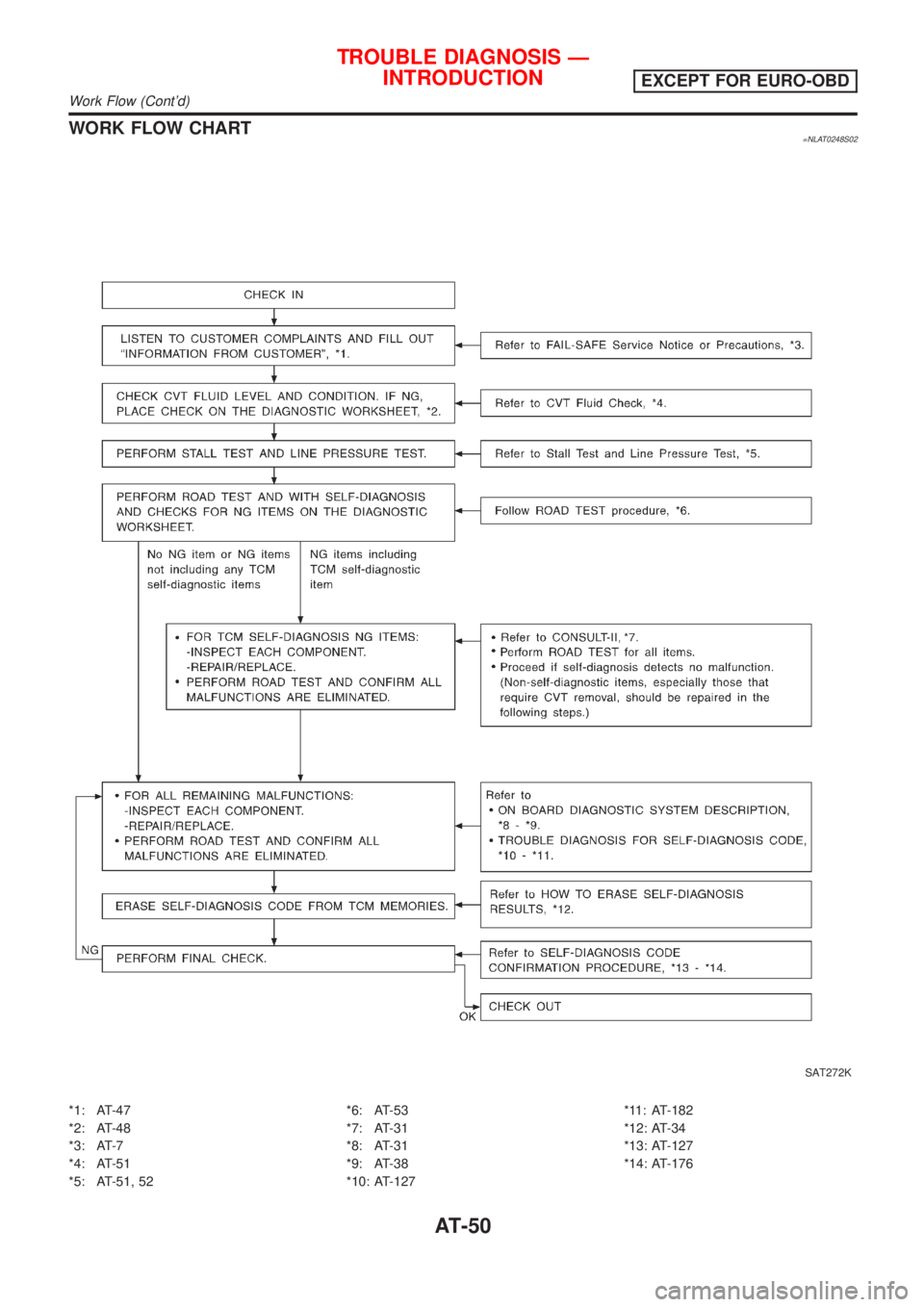
WORK FLOW CHART=NLAT0248S02
SAT272K
*1: AT-47
*2: AT-48
*3: AT-7
*4: AT-51
*5: AT-51, 52*6: AT-53
*7: AT-31
*8: AT-31
*9: AT-38
*10: AT-127*11: AT-182
*12: AT-34
*13: AT-127
*14: AT-176
TROUBLE DIAGNOSIS Ð
INTRODUCTION
EXCEPT FOR EURO-OBD
Work Flow (Cont'd)
AT-50
Page 52 of 3051
SAT767B
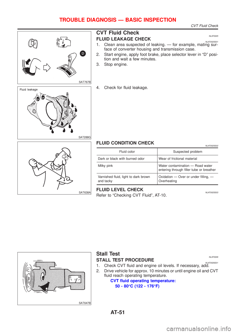
CVT Fluid CheckNLAT0025FLUID LEAKAGE CHECKNLAT0025S011. Clean area suspected of leaking. Ð for example, mating sur-
face of converter housing and transmission case.
2. Start engine, apply foot brake, place selector lever in ªDº posi-
tion and wait a few minutes.
3. Stop engine.
SAT288G
4. Check for fluid leakage.
SAT638A
FLUID CONDITION CHECKNLAT0025S02
Fluid color Suspected problem
Dark or black with burned odor Wear of frictional material
Milky pink Water contamination Ð Road water
entering through filler tube or breather
Varnished fluid, light to dark brown
and tackyOxidation Ð Over or under filling, Ð
Overheating
FLUID LEVEL CHECKNLAT0025S03Refer to ªChecking CVT Fluidº, AT-10.
SAT647B
Stall TestNLAT0026STALL TEST PROCEDURENLAT0026S011. Check CVT fluid and engine oil levels. If necessary, add.
2. Drive vehicle for approx. 10 minutes or until engine oil and CVT
fluid reach operating temperature.
CVT fluid operating temperature:
50 - 80ÉC (122 - 176ÉF)
TROUBLE DIAGNOSIS Ð BASIC INSPECTION
CVT Fluid Check
AT-51
Page 53 of 3051
SAT513G
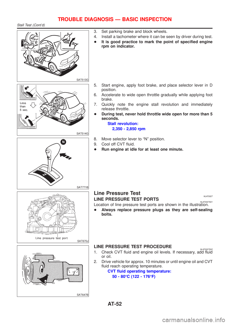
3. Set parking brake and block wheels.
4. Install a tachometer where it can be seen by driver during test.
+It is good practice to mark the point of specified engine
rpm on indicator.
SAT514G
5. Start engine, apply foot brake, and place selector lever in D
position.
6. Accelerate to wide open throttle gradually while applying foot
brake.
7. Quickly note the engine stall revolution and immediately
release throttle.
+During test, never hold throttle wide open for more than 5
seconds.
Stall revolution:
2,350 - 2,850 rpm
SAT771B
8. Move selector lever to ªNº position.
9. Cool off CVT fluid.
+Run engine at idle for at least one minute.
SAT670J
Line Pressure TestNLAT0027LINE PRESSURE TEST PORTSNLAT0027S01Location of line pressure test ports are shown in the illustration.
+Always replace pressure plugs as they are self-sealing
bolts.
SAT647B
LINE PRESSURE TEST PROCEDURENLAT0027S021. Check CVT fluid and engine oil levels. If necessary, add fluid
or oil.
2. Drive vehicle for approx. 10 minutes or until engine oil and CVT
fluid reach operating temperature.
CVT fluid operating temperature:
50 - 80ÉC (122 - 176ÉF)
TROUBLE DIAGNOSIS Ð BASIC INSPECTION
Stall Test (Cont'd)
AT-52
Page 54 of 3051

3. Install pressure gauge to corresponding line pressure port.
SAT513G
4. Set parking brake and block wheels.
+Continue to depress brake pedal fully while line pressure
test is being performed at stall speed.
SAT493G
5. Start engine and measure line pressure at idle and stall speed.
+When measuring line pressure at stall speed, follow the
stall test procedure.
Line pressure: Refer to SDS, AT-210.
SAT692J
Road TestNLAT0028DESCRIPTIONNLAT0028S01+The purpose of the test is to determine overall performance of
CVT and analyze causes of problems.
+The road test consists of the following three parts:
1. Check before engine is started
2. Cruise test
SAT496G
+Before road test, familiarize yourself with all test procedures
and items to check.
+Conduct tests on all items until specified symptom is found.
Troubleshoot items which check out No Good after road test.
Refer to ªON BOARD DIAGNOSTIC SYSTEM
DESCRIPTIONº, AT-18 to AT-28 (EURO-OBD)/AT-31 to AT-38
(Except for EURO-OBD).
TROUBLE DIAGNOSIS Ð BASIC INSPECTION
Line Pressure Test (Cont'd)
AT-53
Page 55 of 3051

1. CHECK BEFORE ENGINE IS STARTED=NLAT0028S02
1 CHECK SPORT INDICATOR LAMP
1. Park vehicle on flat surface.
2. Move selector lever to ªPº position.
SAT967IC
3. Turn ignition switch to ªOFFº position. Wait at least 5 seconds.
4. Turn ignition switch to ªONº position. (Do not start engine.)
5. Does SPORT indicator lamp come on for about 2 seconds?
YesorNo
Ye s©GO TO 2.
No©Stop ROAD TEST.
2 CHECK SPORT INDICATOR LAMP
Does SPORT indicator lamp flicker for about 8 seconds?
YesorNo
Yes (EURO-OBD)©Perform self-diagnosis and check NG items on the DIAGNOSTIC WORKSHEET, AT-43.
Refer to TCM SELF-DIAGNOSIS PROCEDURE (NO TOOLS), AT-28.
Yes (Except for EURO-
OBD)©Perform self-diagnosis and check NG items on the DIAGNOSTIC WORKSHEET, AT-48.
Refer to TCM SELF-DIAGNOSIS PROCEDURE (NO TOOLS), AT-35.
No©1. Turn ignition switch to ªOFFº position.
2. Perform self-diagnosis and note NG items.
Refer to TCM SELF-DIAGNOSIS PROCEDURE (NO TOOLS), AT-28.
3 TEST DRIVE
Drive the vehicle and verify that there are no abnormalities.
©TEST END
SAT601J
2. CRUISE TESTNLAT0028S04+Check all items listed in Parts 1 through 3.
With CONSULT-IINLAT0028S0401+Using CONSULT-II, conduct a cruise test and record the result.
+Print the result and ensure that shifts and lock-ups take place
as per Shift Schedule.
TROUBLE DIAGNOSIS Ð BASIC INSPECTION
Road Test (Cont'd)
AT-54
Page 56 of 3051
SAT228K
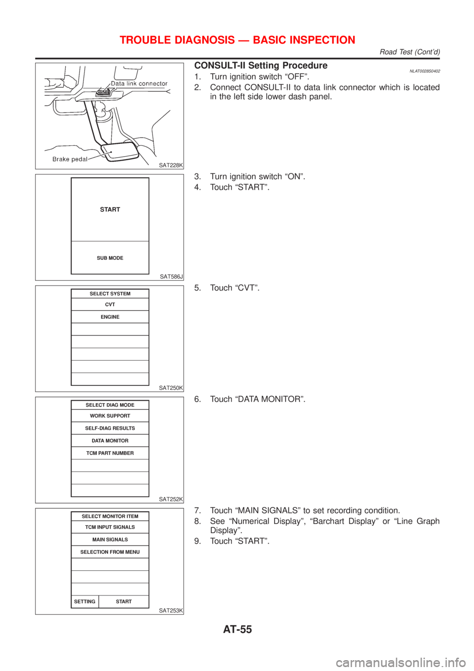
CONSULT-II Setting ProcedureNLAT0028S04021. Turn ignition switch ªOFFº.
2. Connect CONSULT-II to data link connector which is located
in the left side lower dash panel.
SAT586J
3. Turn ignition switch ªONº.
4. Touch ªSTARTº.
SAT250K
5. Touch ªCVTº.
SAT252K
6. Touch ªDATA MONITORº.
SAT253K
7. Touch ªMAIN SIGNALSº to set recording condition.
8. See ªNumerical Displayº, ªBarchart Displayº or ªLine Graph
Displayº.
9. Touch ªSTARTº.
TROUBLE DIAGNOSIS Ð BASIC INSPECTION
Road Test (Cont'd)
AT-55
Page 57 of 3051

SAT236K
10. When performing cruise test, touch ªStore Dataº.
SAT237K
11. After finishing cruise test part 1, touch ªSTOPº.
SAT254K
12. Touch ªSTOREº.
SAT608J
13. Touch ªDISPLAYº.
SAT238K
14. Touch ªPRINTº.
15. Check the monitor data printed out.
16. Continue cruise test part 2 and 3.
TROUBLE DIAGNOSIS Ð BASIC INSPECTION
Road Test (Cont'd)
AT-56
Page 58 of 3051

SAT417J
Without CONSULT-IINLAT0028S0403+Throttle position sensor can be checked by voltage across
terminals 41 and 42 of TCM.
Refer to ªRoad Testº, AT-53.
TROUBLE DIAGNOSIS Ð BASIC INSPECTION
Road Test (Cont'd)
AT-57
Page 59 of 3051
SAT216J
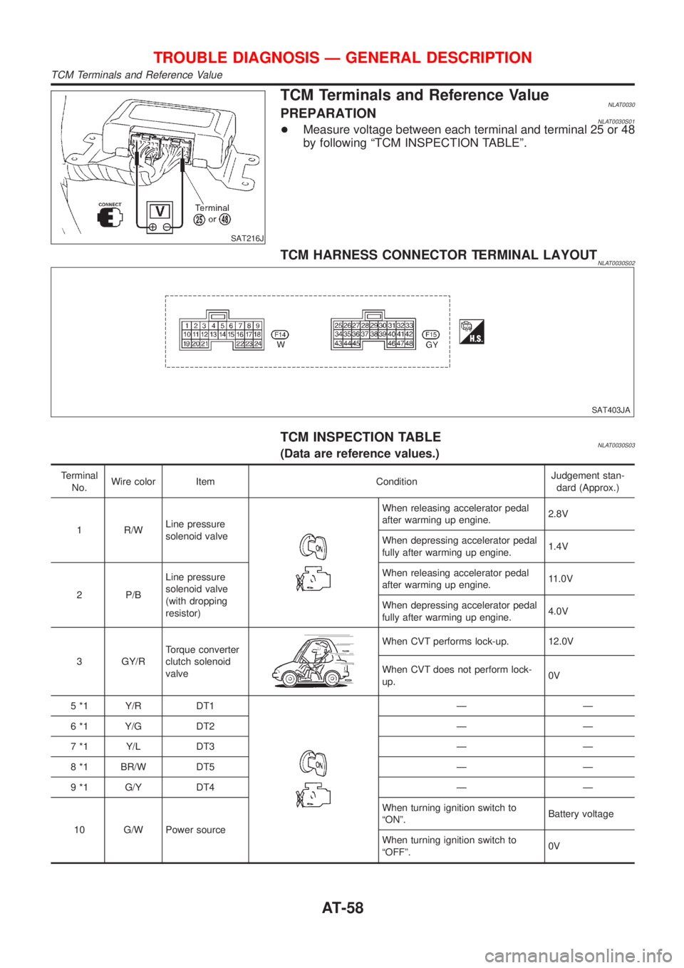
TCM Terminals and Reference ValueNLAT0030PREPARATIONNLAT0030S01+Measure voltage between each terminal and terminal 25 or 48
by following ªTCM INSPECTION TABLEº.
TCM HARNESS CONNECTOR TERMINAL LAYOUTNLAT0030S02
SAT403JA
TCM INSPECTION TABLENLAT0030S03(Data are reference values.)
Terminal
No.Wire color Item ConditionJudgement stan-
dard (Approx.)
1 R/WLine pressure
solenoid valve
When releasing accelerator pedal
after warming up engine.2.8V
When depressing accelerator pedal
fully after warming up engine.1.4V
2 P/BLine pressure
solenoid valve
(with dropping
resistor)When releasing accelerator pedal
after warming up engine.11.0V
When depressing accelerator pedal
fully after warming up engine.4.0V
3 GY/RTorque converter
clutch solenoid
valve
When CVT performs lock-up. 12.0V
When CVT does not perform lock-
up.0V
5 *1 Y/R DT1
ÐÐ
6 *1 Y/G DT2 Ð Ð
7 *1 Y/L DT3 Ð Ð
8 *1 BR/W DT5 Ð Ð
9 *1 G/Y DT4 Ð Ð
10 G/W Power sourceWhen turning ignition switch to
ªONº.Battery voltage
When turning ignition switch to
ªOFFº.0V
TROUBLE DIAGNOSIS Ð GENERAL DESCRIPTION
TCM Terminals and Reference Value
AT-58
Page 60 of 3051
Terminal
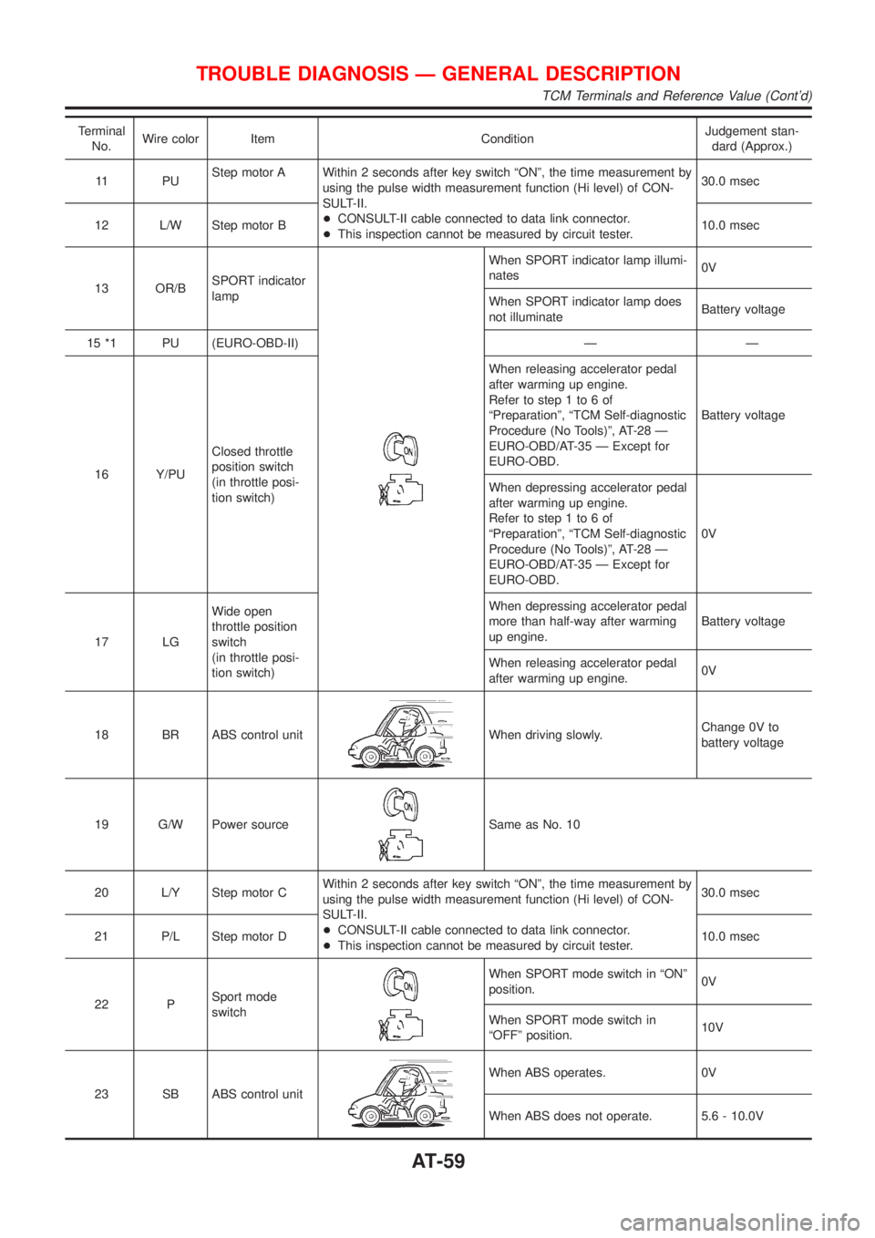
No.Wire color Item ConditionJudgement stan-
dard (Approx.)
11 P UStep motor A Within 2 seconds after key switch ªONº, the time measurement by
using the pulse width measurement function (Hi level) of CON-
SULT-II.
+CONSULT-II cable connected to data link connector.
+This inspection cannot be measured by circuit tester.30.0 msec
12 L/W Step motor B10.0 msec
13 OR/BSPORT indicator
lamp
When SPORT indicator lamp illumi-
nates0V
When SPORT indicator lamp does
not illuminateBattery voltage
15 *1 PU (EURO-OBD-II) Ð Ð
16 Y/PUClosed throttle
position switch
(in throttle posi-
tion switch)When releasing accelerator pedal
after warming up engine.
Refer to step 1 to 6 of
ªPreparationº, ªTCM Self-diagnostic
Procedure (No Tools)º, AT-28 Ð
EURO-OBD/AT-35 Ð Except for
EURO-OBD.Battery voltage
When depressing accelerator pedal
after warming up engine.
Refer to step 1 to 6 of
ªPreparationº, ªTCM Self-diagnostic
Procedure (No Tools)º, AT-28 Ð
EURO-OBD/AT-35 Ð Except for
EURO-OBD.0V
17 LGWide open
throttle position
switch
(in throttle posi-
tion switch)When depressing accelerator pedal
more than half-way after warming
up engine.Battery voltage
When releasing accelerator pedal
after warming up engine.0V
18 BR ABS control unit
When driving slowly.Change 0V to
battery voltage
19 G/W Power source
Same as No. 10
20 L/Y Step motor CWithin 2 seconds after key switch ªONº, the time measurement by
using the pulse width measurement function (Hi level) of CON-
SULT-II.
+CONSULT-II cable connected to data link connector.
+This inspection cannot be measured by circuit tester.30.0 msec
21 P/L Step motor D10.0 msec
22 PSport mode
switch
When SPORT mode switch in ªONº
position.0V
When SPORT mode switch in
ªOFFº position.10V
23 SB ABS control unit
When ABS operates. 0V
When ABS does not operate. 5.6 - 10.0V
TROUBLE DIAGNOSIS Ð GENERAL DESCRIPTION
TCM Terminals and Reference Value (Cont'd)
AT-59