NISSAN ALMERA TINO 2001 Service Repair Manual
Manufacturer: NISSAN, Model Year: 2001, Model line: ALMERA TINO, Model: NISSAN ALMERA TINO 2001Pages: 3051, PDF Size: 46.38 MB
Page 971 of 3051
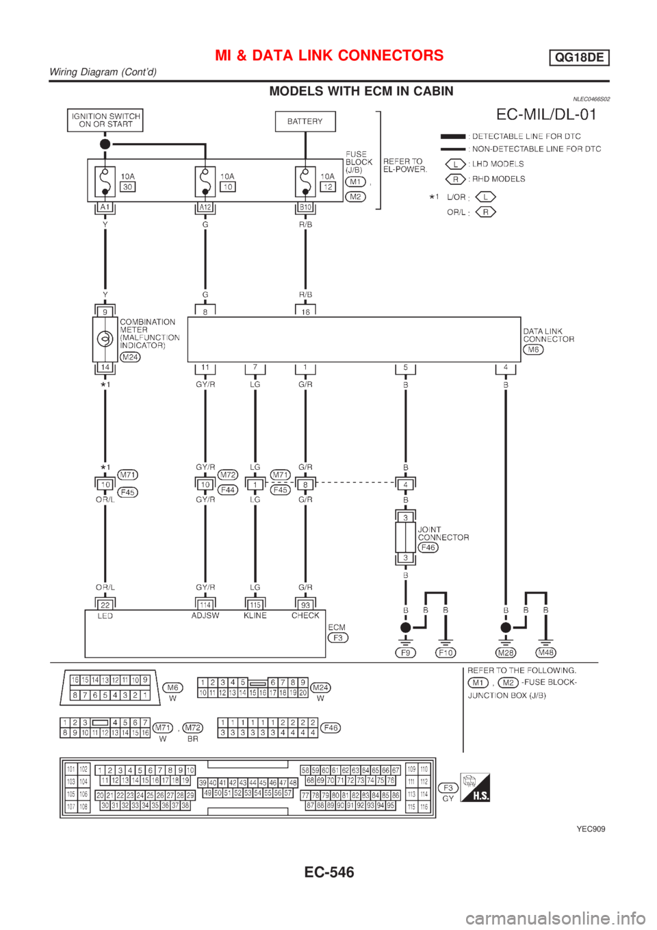
MODELS WITH ECM IN CABINNLEC0466S02
YEC909
MI & DATA LINK CONNECTORSQG18DE
Wiring Diagram (Cont'd)
EC-546
Page 972 of 3051
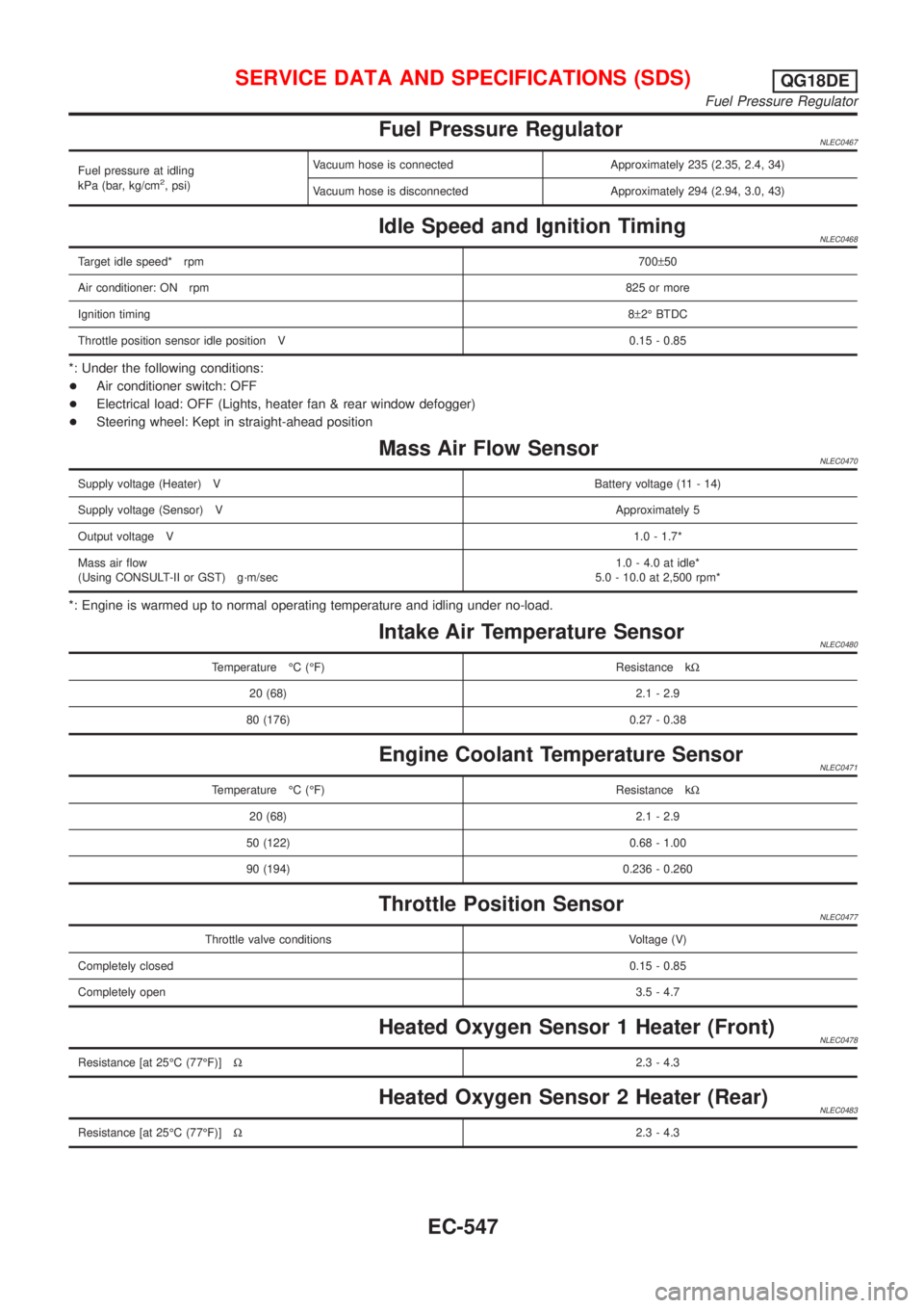
Fuel Pressure RegulatorNLEC0467
Fuel pressure at idling
kPa (bar, kg/cm2, psi)Vacuum hose is connected Approximately 235 (2.35, 2.4, 34)
Vacuum hose is disconnected Approximately 294 (2.94, 3.0, 43)
Idle Speed and Ignition TimingNLEC0468
Target idle speed* rpm700±50
Air conditioner: ON rpm825 or more
Ignition timing8±2É BTDC
Throttle position sensor idle position V 0.15 - 0.85
*: Under the following conditions:
+Air conditioner switch: OFF
+Electrical load: OFF (Lights, heater fan & rear window defogger)
+Steering wheel: Kept in straight-ahead position
Mass Air Flow SensorNLEC0470
Supply voltage (Heater) VBattery voltage (11 - 14)
Supply voltage (Sensor) VApproximately 5
Output voltage V1.0 - 1.7*
Mass air flow
(Using CONSULT-II or GST) g´m/sec1.0 - 4.0 at idle*
5.0 - 10.0 at 2,500 rpm*
*: Engine is warmed up to normal operating temperature and idling under no-load.
Intake Air Temperature SensorNLEC0480
Temperature ÉC (ÉF) Resistance kW
20 (68) 2.1 - 2.9
80 (176) 0.27 - 0.38
Engine Coolant Temperature SensorNLEC0471
Temperature ÉC (ÉF) Resistance kW
20 (68) 2.1 - 2.9
50 (122) 0.68 - 1.00
90 (194) 0.236 - 0.260
Throttle Position SensorNLEC0477
Throttle valve conditions Voltage (V)
Completely closed0.15 - 0.85
Completely open3.5 - 4.7
Heated Oxygen Sensor 1 Heater (Front)NLEC0478
Resistance [at 25ÉC (77ÉF)]W2.3 - 4.3
Heated Oxygen Sensor 2 Heater (Rear)NLEC0483
Resistance [at 25ÉC (77ÉF)]W2.3 - 4.3
SERVICE DATA AND SPECIFICATIONS (SDS)QG18DE
Fuel Pressure Regulator
EC-547
Page 973 of 3051
![NISSAN ALMERA TINO 2001 Service Repair Manual EGR Volume Control Valve (where fitted)NLEC0560
Terminal No. ResistanceW[at 20ÉC (68ÉF)]
1-2
20-24 2-3
4-5
5-6
EGR Temperature Sensor (where fitted)NLEC0472
EGR temperature
ÉC (ÉF)Voltage
VResista NISSAN ALMERA TINO 2001 Service Repair Manual EGR Volume Control Valve (where fitted)NLEC0560
Terminal No. ResistanceW[at 20ÉC (68ÉF)]
1-2
20-24 2-3
4-5
5-6
EGR Temperature Sensor (where fitted)NLEC0472
EGR temperature
ÉC (ÉF)Voltage
VResista](/img/5/57352/w960_57352-972.png)
EGR Volume Control Valve (where fitted)NLEC0560
Terminal No. ResistanceW[at 20ÉC (68ÉF)]
1-2
20-24 2-3
4-5
5-6
EGR Temperature Sensor (where fitted)NLEC0472
EGR temperature
ÉC (ÉF)Voltage
VResistance
MW
0 (32) 4.56 0.62 - 1.05
50 (122) 2.25 0.065 - 0.094
100 (212) 0.59 0.011 - 0.015
EVAP Canister Purge Volume Control ValveNLEC0481
Resistance [at 20ÉC (68ÉF)]W31-35
IACV-AAC ValveNLEC0474
Terminal No. ResistanceW[at 20ÉC (68ÉF)]
1-2
20-24 2-3
4-5
5-6
InjectorNLEC0475
Resistance [at 25ÉC (77ÉF)]W13.5 - 17.5
Ignition Coil with Power TransistorNLEC0561
Terminal No. (Polarity) ResistanceW[at 25ÉC (77ÉF)]
3 (+) - 2 (þ) Except 0 or¥
1 (+) - 3 (þ)
Except 0
1 (+) - 2 (þ)
CondenserNLEC0587
Resistance [at 25ÉC (77ÉF)] MWAbove 1
Fuel PumpNLEC0473
Resistance [at 25ÉC (77ÉF)]W0.2 - 5.0
SERVICE DATA AND SPECIFICATIONS (SDS)QG18DE
EGR Volume Control Valve (where fitted)
EC-548
Page 974 of 3051

Crankshaft Position Sensor (POS)NLEC0558Refer to ªComponent Inspectionº, EC-301.
Camshaft Position Sensor (PHASE)NLEC0559Refer to ªComponent Inspectionº, EC-308.
SERVICE DATA AND SPECIFICATIONS (SDS)QG18DE
Crankshaft Position Sensor (POS)
EC-549
Page 975 of 3051
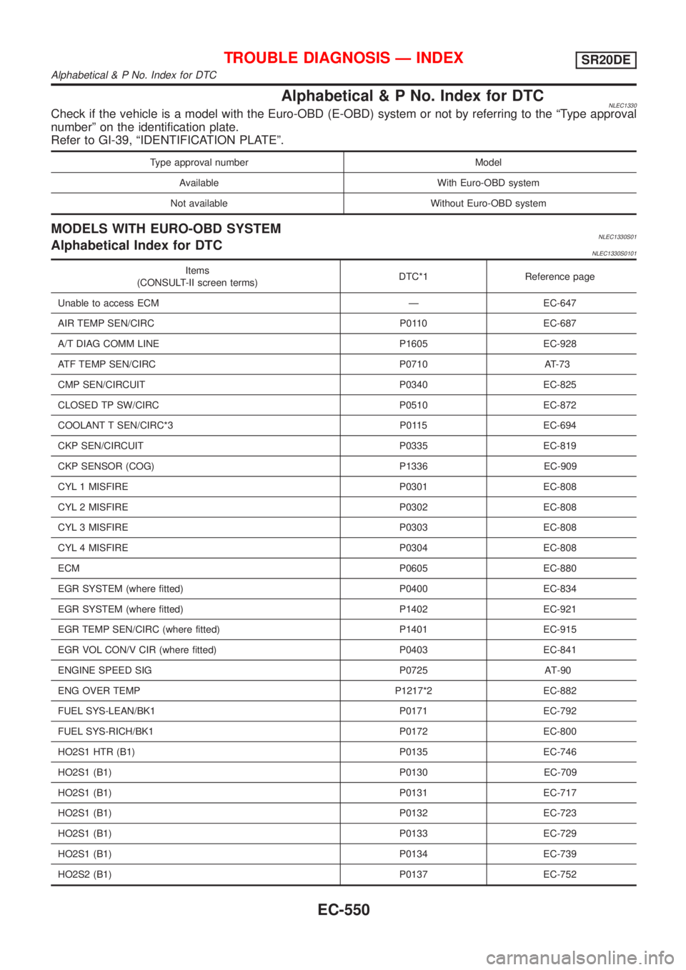
Alphabetical&PNo .Inde xfo rDTC
Typ eapprova lnumber Model
Items
Alphabetical & P No. Index for DTC
Page 976 of 3051
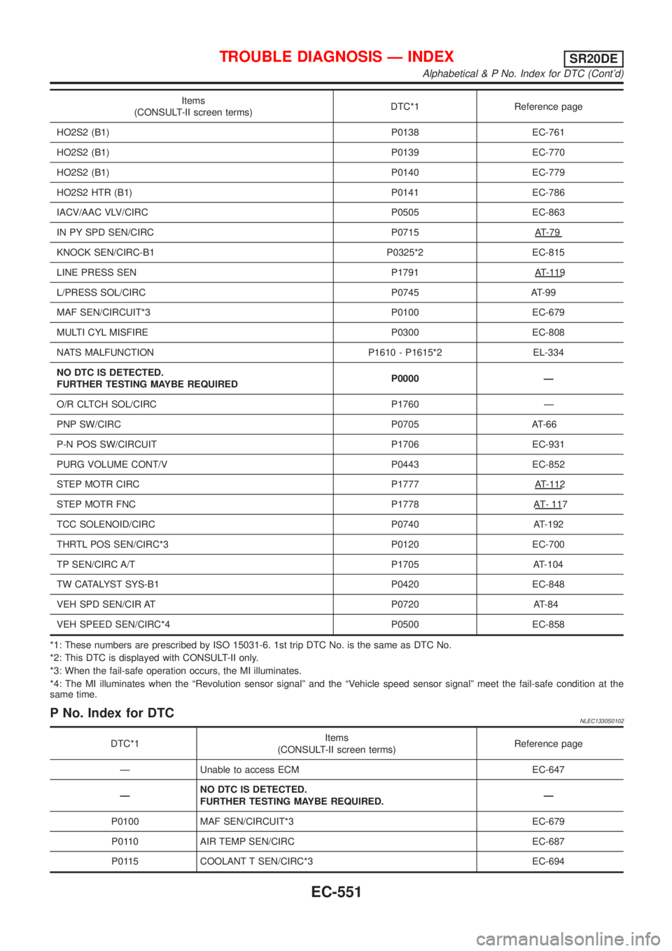
Items
KNOCKSEN/CIRC-B1 P0325*2 EC-815
L/PRESSSOL/CIRC P0745 A T-99
STE PMOT RFNC P1778 AT- 117
TCCSOLENOID/CIRC P0740 AT-192
DTC*1
Alphabetical & P No. Index for DTC (Cont'd)
Page 977 of 3051
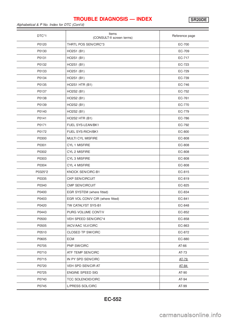
DTC*1
P0720 VEHSP DSEN/CI RAT AT-84
P0725 ENGINESPEE DSIG AT-90
Alphabetical & P No. Index for DTC (Cont'd)
Page 978 of 3051
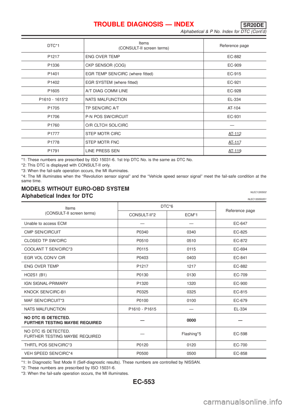
DTC*1
P1778 STEPMOT RFNC AT-117
P1791 LINEPRES SSEN AT-119
*1 :Thes enumber sar eprescribe dby IS O 15031-6 .1s ttri p DT CNo .is th e sam eas DT CNo.
Items
Alphabetical & P No. Index for DTC (Cont'd)
Page 979 of 3051
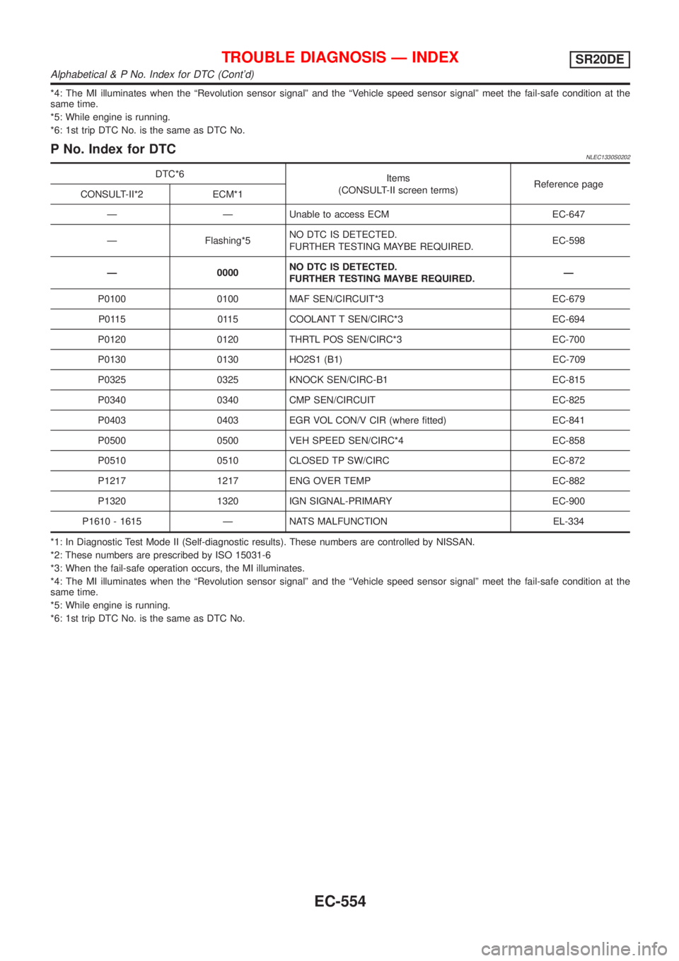
*4: The MI illuminates when the ªRevolution sensor signalº and the ªVehicle speed sensor signalº meet the fail-safe condition at the
same time.
*5: While engine is running.
*6: 1st trip DTC No. is the same as DTC No.
P No. Index for DTCNLEC1330S0202
DTC*6
Items
(CONSULT-II screen terms)Reference page
CONSULT-II*2 ECM*1
Ð Ð Unable to access ECM EC-647
Ð Flashing*5NO DTC IS DETECTED.
FURTHER TESTING MAYBE REQUIRED.EC-598
Ð 0000NO DTC IS DETECTED.
FURTHER TESTING MAYBE REQUIRED.Ð
P0100 0100 MAF SEN/CIRCUIT*3 EC-679
P0115 0115 COOLANT T SEN/CIRC*3 EC-694
P0120 0120 THRTL POS SEN/CIRC*3 EC-700
P0130 0130 HO2S1 (B1) EC-709
P0325 0325 KNOCK SEN/CIRC-B1 EC-815
P0340 0340 CMP SEN/CIRCUIT EC-825
P0403 0403 EGR VOL CON/V CIR (where fitted) EC-841
P0500 0500 VEH SPEED SEN/CIRC*4 EC-858
P0510 0510 CLOSED TP SW/CIRC EC-872
P1217 1217 ENG OVER TEMP EC-882
P1320 1320 IGN SIGNAL-PRIMARY EC-900
P1610 - 1615 Ð NATS MALFUNCTION EL-334
*1: In Diagnostic Test Mode II (Self-diagnostic results). These numbers are controlled by NISSAN.
*2: These numbers are prescribed by ISO 15031-6
*3: When the fail-safe operation occurs, the MI illuminates.
*4: The MI illuminates when the ªRevolution sensor signalº and the ªVehicle speed sensor signalº meet the fail-safe condition at the
same time.
*5: While engine is running.
*6: 1st trip DTC No. is the same as DTC No.
TROUBLE DIAGNOSIS Ð INDEXSR20DE
Alphabetical & P No. Index for DTC (Cont'd)
EC-554
Page 980 of 3051
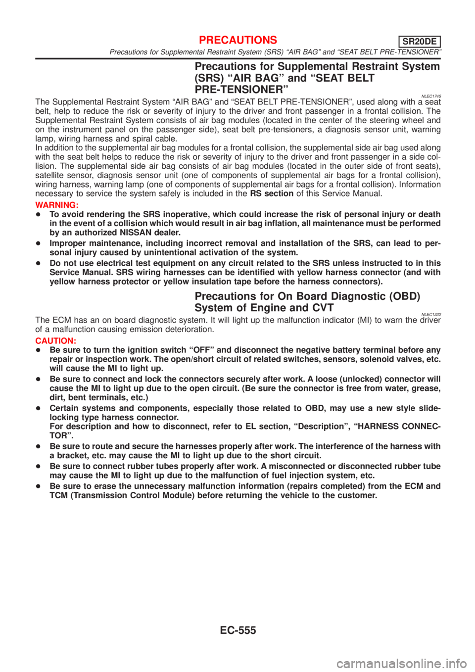
Precautions for Supplemental Restraint System
(SRS) ªAIR BAGº and ªSEAT BELT
PRE-TENSIONERº
NLEC1745The Supplemental Restraint System ªAIR BAGº and ªSEAT BELT PRE-TENSIONERº, used along with a seat
belt, help to reduce the risk or severity of injury to the driver and front passenger in a frontal collision. The
Supplemental Restraint System consists of air bag modules (located in the center of the steering wheel and
on the instrument panel on the passenger side), seat belt pre-tensioners, a diagnosis sensor unit, warning
lamp, wiring harness and spiral cable.
In addition to the supplemental air bag modules for a frontal collision, the supplemental side air bag used along
with the seat belt helps to reduce the risk or severity of injury to the driver and front passenger in a side col-
lision. The supplemental side air bag consists of air bag modules (located in the outer side of front seats),
satellite sensor, diagnosis sensor unit (one of components of supplemental air bags for a frontal collision),
wiring harness, warning lamp (one of components of supplemental air bags for a frontal collision). Information
necessary to service the system safely is included in theRS sectionof this Service Manual.
WARNING:
+To avoid rendering the SRS inoperative, which could increase the risk of personal injury or death
in the event of a collision which would result in air bag inflation, all maintenance must be performed
by an authorized NISSAN dealer.
+Improper maintenance, including incorrect removal and installation of the SRS, can lead to per-
sonal injury caused by unintentional activation of the system.
+Do not use electrical test equipment on any circuit related to the SRS unless instructed to in this
Service Manual. SRS wiring harnesses can be identified with yellow harness connector (and with
yellow harness protector or yellow insulation tape before the harness connectors).
Precautions for On Board Diagnostic (OBD)
System of Engine and CVT
NLEC1332The ECM has an on board diagnostic system. It will light up the malfunction indicator (MI) to warn the driver
of a malfunction causing emission deterioration.
CAUTION:
+Be sure to turn the ignition switch ªOFFº and disconnect the negative battery terminal before any
repair or inspection work. The open/short circuit of related switches, sensors, solenoid valves, etc.
will cause the MI to light up.
+Be sure to connect and lock the connectors securely after work. A loose (unlocked) connector will
cause the MI to light up due to the open circuit. (Be sure the connector is free from water, grease,
dirt, bent terminals, etc.)
+Certain systems and components, especially those related to OBD, may use a new style slide-
locking type harness connector.
For description and how to disconnect, refer to EL section, ªDescriptionº, ªHARNESS CONNEC-
TORº.
+Be sure to route and secure the harnesses properly after work. The interference of the harness with
a bracket, etc. may cause the MI to light up due to the short circuit.
+Be sure to connect rubber tubes properly after work. A misconnected or disconnected rubber tube
may cause the MI to light up due to the malfunction of fuel injection system, etc.
+Be sure to erase the unnecessary malfunction information (repairs completed) from the ECM and
TCM (Transmission Control Module) before returning the vehicle to the customer.
PRECAUTIONSSR20DE
Precautions for Supplemental Restraint System (SRS) ªAIR BAGº and ªSEAT BELT PRE-TENSIONERº
EC-555