NISSAN LATIO 2009 Service Repair Manual
LATIO 2009
NISSAN
NISSAN
https://www.carmanualsonline.info/img/5/57359/w960_57359-0.png
NISSAN LATIO 2009 Service Repair Manual
Trending: transmission fluid, Drive belt, ad blue, sensor, brake rotor, turn signal bulb, brake sensor
Page 1701 of 4331
EC
NP
O
P0462, P0463 FUEL LEVEL SENSOR
Description INFOID:0000000004780217
The fuel level sensor is mounted in the fuel level sensor unit.
The sensor detects a fuel level in the fuel tank and tr ansmits a signal to the combination meter. The combina-
tion meter sends the fuel level sensor signal to the ECM via the CAN communication line.
It consists of two parts, one is mechanical float and the ot her is variable resistor. Fuel level sensor output volt-
age changes depending on the movement of the fuel mechanical float.
DTC Logic INFOID:0000000004780218
DTC DETECTION LOGIC NOTE:
• If DTC P0462 or P0463 is displayed with DTC UXXXX, first perform the trouble diagnosis for DTC
UXXXX.
• If DTC P0462 or P0463 is displayed with DTC P0607, first perform the trouble diagnosis for DTC
P0607. Refer to EC-357, " DTC Logic " .
This diagnosis indicates the former, to detect open or short circuit malfunction.
DTC CONFIRMATION PROCEDURE YES >> Go to
EC-345, " Diagnosis Procedure " .
NO >> INSPECTION END
Diagnosis Procedure INFOID:0000000004780219Trouble Diagnosis " .
Is the inspection result normal? YES >> GO TO 2.
NO >> Refer to DI-13, " Trouble Diagnosis "
Diagnosis Procedure " .
DTC No. Trouble diagnosis name DTC detecting condition Possible cause
P0462 Fuel level sensor circuit
low input An excessively low voltage from the sensor is
sent to ECM. • Harness or connectors
(The CAN communication line is open or
shorted)
• Harness or connectors (The sensor circuit is open or shorted)
• Combination meter
• Fuel level sensor
P0463
Fuel level sensor circuit
high input An excessively high voltage from the sensor is
sent to ECM.
Page 1702 of 4331
Page 1703 of 4331
EC
NP
O
P0500 VSS
Description INFOID:0000000004780220
The vehicle speed signal is sent to the combination me ter from the “ABS actuator and electric unit (control
unit)” via the CAN communication line. The combinati on meter then sends a signal to the ECM via the CAN
communication line.
DTC Logic INFOID:0000000004780221
DTC DETECTION LOGIC NOTE:
• If DTC P0500 is displayed with DTC UXXXX, first perform the tr ouble diagnosis for DTC UXXXX.
• If DTC P0500 is displayed with DT C P0607, first perform the trouble diagnosis for DTC P0607. Refer
to EC-357, " DTC Logic " .
DTC CONFIRMATION PROCEDURE YES >> GO TO 2.
NO >> GO TO 5. YES >> GO TO 2.
NO >> Go to EC-348, " Diagnosis Procedure " .
Page 1704 of 4331
YES >> Go to
EC-348, " Diagnosis Procedure " .
NO >> INSPECTION END Component Function Check " .
Use component function check to check the overall func tion of the vehicle speed signal circuit. During this
check, a 1st trip DTC might not be confirmed.
Is the inspection result normal? YES >> INSPECTION END
NO >> Go to EC-348, " Diagnosis Procedure " .
Component Function Check INFOID:0000000004780222YES >> INSPECTION END
NO >> Go to EC-348, " Diagnosis Procedure " .
Diagnosis Procedure INFOID:0000000004780223CONSULT-III Function (ABS) " .
Is the inspection result normal? YES >> GO TO 2.
NO >> Repair or replace. CONSULT-III Function (METER/M&A) " .
>> INSPECTION END
ENG SPEED
A/T: 1,900 - 6,000 rpm
M/T: 2,500 - 6,000 rpm
COOLAN TEMP/S More than 70 °C (158 °F)
B/FUEL SCHDL A/T: 4.8 - 31.8 msec
M/T: 3.8 - 31.8 msec
Selector lever Except P or N position (A/T)
Except Neutral position (M/T)
PW/ST SIGNAL OFF
Page 1705 of 4331
EC
NP
O
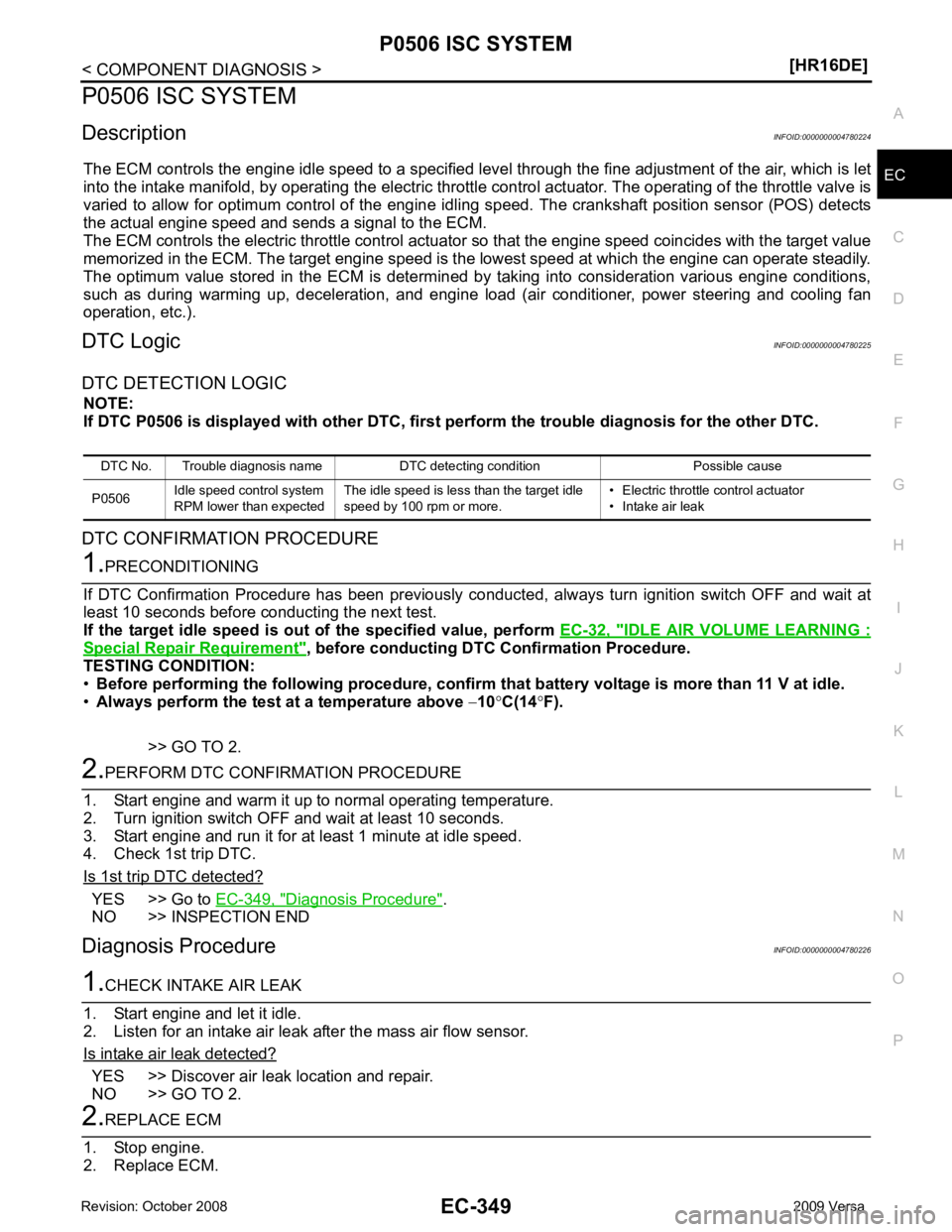
P0506 ISC SYSTEM
Description INFOID:0000000004780224
The ECM controls the engine idle speed to a specified leve l through the fine adjustment of the air, which is let
into the intake manifold, by operating the electric thrott le control actuator. The operating of the throttle valve is
varied to allow for optimum control of the engine idli ng speed. The crankshaft position sensor (POS) detects
the actual engine speed and sends a signal to the ECM.
The ECM controls the electric throttle control actuator so that the engine speed coincides with the target value
memorized in the ECM. The target engine speed is t he lowest speed at which the engine can operate steadily.
The optimum value stored in the ECM is determined by taking into consideration various engine conditions,
such as during warming up, deceleration, and engine load (air conditioner, power steering and cooling fan
operation, etc.).
DTC Logic INFOID:0000000004780225
DTC DETECTION LOGIC NOTE:
If DTC P0506 is displayed with ot her DTC, first perform the trouble diagnosis for the other DTC.
DTC CONFIRMATION PROCEDURE IDLE AIR VOLUME LEARNING :
Special Repair Requirement " , before conducting DTC Confirmation Procedure.
TESTING CONDITION:
• Before performing the following procedure, confirm that battery voltage is more than 11 V at idle.
• Always perform the test at a temperature above −10 °C(14 °F).
>> GO TO 2. YES >> Go to
EC-349, " Diagnosis Procedure " .
NO >> INSPECTION END
Diagnosis Procedure INFOID:0000000004780226YES >> Discover air leak location and repair.
NO >> GO TO 2.
Page 1706 of 4331
ADDITIONAL SERVICE WHEN REPLACING CO
NTROL UNIT : Special Repair Require-ment " .
>> INSPECTION END
Page 1707 of 4331
EC
NP
O
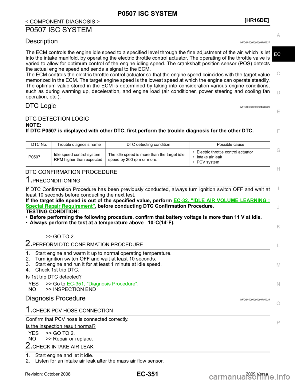
P0507 ISC SYSTEM
Description INFOID:0000000004780227
The ECM controls the engine idle speed to a specified leve l through the fine adjustment of the air, which is let
into the intake manifold, by operating the electric thrott le control actuator. The operating of the throttle valve is
varied to allow for optimum control of the engine idli ng speed. The crankshaft position sensor (POS) detects
the actual engine speed and sends a signal to the ECM.
The ECM controls the electric throttle control actuator so that the engine speed coincides with the target value
memorized in the ECM. The target engine speed is t he lowest speed at which the engine can operate steadily.
The optimum value stored in the ECM is determined by taking into consideration various engine conditions,
such as during warming up, deceleration, and engine load (air conditioner, power steering and cooling fan
operation, etc.).
DTC Logic INFOID:0000000004780228
DTC DETECTION LOGIC NOTE:
If DTC P0507 is displayed with ot her DTC, first perform the trouble diagnosis for the other DTC.
DTC CONFIRMATION PROCEDURE IDLE AIR VOLUME LEARNING :
Special Repair Requirement " , before conducting DTC Confirmation Procedure.
TESTING CONDITION:
• Before performing the following procedure, confirm that battery voltage is more than 11 V at idle.
• Always perform the test at a temperature above −10 °C(14 °F).
>> GO TO 2. YES >> Go to
EC-351, " Diagnosis Procedure " .
NO >> INSPECTION END
Diagnosis Procedure INFOID:0000000004780229YES >> GO TO 2.
NO >> Repair or replace.
Page 1708 of 4331
YES >> Discover air leak location and repair.
NO >> GO TO 3. ADDITIONAL SERVICE WHEN REPLACING CO
NTROL UNIT : Special Repair Require-ment " .
>> INSPECTION END
Page 1709 of 4331
EC
NP
O
P0603 ECM POWER SUPPLY
Description INFOID:0000000004780234
ECM has the memory function of the DTC memory, the air-fuel ratio
feedback compensation value memory, the idle air volume learning
value memory, etc. even when the ignition switch is turned ON.
DTC Logic INFOID:0000000004780235
DTC DETECTION LOGIC
DTC CONFIRMATION PROCEDURE YES >> Go to
EC-353, " Diagnosis Procedure " .
NO >> INSPECTION END
Diagnosis Procedure INFOID:0000000004780236Diagnosis Description " .
3. Perform DTC CONFIRMATION PROCEDURE. Refer to EC-353, " DTC Logic " .
Is the 1st trip DTC P0603 displayed again? YES >> GO TO 2.
NO >> INSPECTION END ADDITIONAL SERVICE WHEN REPLACING CONTROL UNIT : Special Repair Require-
ment " .
Page 1710 of 4331
Trending: refrigerant type, fuel type, trunk, transmission oil, air filter, seats, radiator


