NISSAN LATIO 2009 Service Repair Manual
Manufacturer: NISSAN, Model Year: 2009, Model line: LATIO, Model: NISSAN LATIO 2009Pages: 4331, PDF Size: 58.04 MB
Page 3181 of 4331
![NISSAN LATIO 2009 Service Repair Manual EM-234< SERVICE INFORMATION >
[MR18DE]
SERVICE DATA AND SPECIFICATIONS (SDS)
Unit: mm (in)
CONNECTING ROD Unit: mm (in)
*: After installing in connecting rod
CRANKSHAFT Unit: mm (in)
Items Standard Li NISSAN LATIO 2009 Service Repair Manual EM-234< SERVICE INFORMATION >
[MR18DE]
SERVICE DATA AND SPECIFICATIONS (SDS)
Unit: mm (in)
CONNECTING ROD Unit: mm (in)
*: After installing in connecting rod
CRANKSHAFT Unit: mm (in)
Items Standard Li](/img/5/57359/w960_57359-3180.png)
EM-234< SERVICE INFORMATION >
[MR18DE]
SERVICE DATA AND SPECIFICATIONS (SDS)
Unit: mm (in)
CONNECTING ROD Unit: mm (in)
*: After installing in connecting rod
CRANKSHAFT Unit: mm (in)
Items Standard Limit
Piston pin outer diameter 19.989 - 19.995 (0.7870 - 0.7872) —
Piston to piston pin oil clearance 0.002 - 0.006 (0.0001 - 0.0002) —
Connecting rod bushing oil clearance 0.005 - 0.023 (0.0002 - 0.0009) 0.03 (0.0012) Center distance
143.44 - 143.54 (5.647 - 5.650)
Bend [per 100 (3.94)] Limit 0.15 (0.0059)
Torsion [per 100 (3.94)] Limit 0.30 (0.0118)
Connecting rod bushing inner diameter* 20.000 - 20.012 (0.7874 - 0.7879)
Side clearance Standard 0.20 - 0.35 (0.0079 - 0.0138)
Limit 0.40 (0.0157)
Connecting rod big end diameter Grade No. A
Grade No. B
Grade No. C
Grade No. D
Grade No. E
Grade No. F
Grade No. G
Grade No. H
Grade No. J
Grade No. K
Grade No. L
Grade No. M
Grade No. N 47.000 - 47.001 (1.8504 - 1.8504)
47.001 - 47.002 (1.8504 - 1.8505)
47.002 - 47.003 (1.8505 - 1.8505)
47.003 - 47.004 (1.8505 - 1.8505)
47.004 - 47.005 (1.8505 - 1.8506)
47.005 - 47.006 (1.8506 - 1.8506)
47.006 - 47.007 (1.8506 - 1.8507)
47.007 - 47.008 (1.8507 - 1.8507)
47.008 - 47.009 (1.8507- 1.8507)
47.009 - 47.010 (1.8507- 1.8508)
47.010 - 47.011 (1.8508 - 1.8508)
47.011 - 47.012 (1.8508 - 1.8509)
47.012 - 47.013 (1.8509 - 1.8509) Center distance (r)
40.41 - 40.49 (1.5909 - 1.5940)
Out-of-round [Difference between (X) and (Y)] Limit 0.0035 (0.0001)
Taper [Difference between (A) and (B)] Limit 0.0035 (0.0001)
Runout [TIR*] Standard 0.05 (0.0020)
Limit 0.10 (0.0040)
Crankshaft end play Standard 0.10 - 0.26 (0.0039 - 0.0102)
Limit 0.30 (0.012) SEM645 PBIC3459J
Page 3182 of 4331

EM
NP
O
*: Total indicator reading
MAIN BEARING Unit: mm (in)
Pin journal diameter grade. (Dp)
Grade No. A
Grade No. B
Grade No. C
Grade No. D
Grade No. E
Grade No. F
Grade No. G
Grade No. H
Grade No. J
Grade No. K
Grade No. L
Grade No. M
Grade No. N
Grade No. P
Grade No. R
Grade No. S
Grade No. T
Grade No. U 43.970 - 43.971 (1.7311 - 1.7311)
43.969 - 43.970 (1.7311 - 1.7311)
43.968 - 43.969 (1.7310 - 1.7311)
43.967 - 43.968 (1.7310 - 1.7310)
43.966 - 43.967 (1.7309 - 1.7310)
43.965 - 43.966 (1.7309 - 1.7309)
43.964 - 43.965 (1.7309 - 1.7309)
43.963 - 43.964 (1.7308 - 1.7309)
43.962 - 43.963 (1.7308 - 1.7308)
43.961 - 43.962 (1.7307 - 1.7308)
43.960 - 43.961 (1.7307 - 1.7307)
43.959 - 43.960 (1.7307 - 1.7307)
43.958 - 43.959 (1.7306 - 1.7307)
43.957 - 43.958 (1.7306 - 1.7306)
43.956 - 43.957 (1.7305 - 1.7306)
43.955 - 43.956 (1.7305 - 1.7305)
43.954 - 43.955 (1.7305 - 1.7305)
43.953 - 43.954 (1.7304 - 1.7305)
Main journal diameter grade. (Dm) Grade No. A
Grade No. B
Grade No. C
Grade No. D
Grade No. E
Grade No. F
Grade No. G
Grade No. H
Grade No. J
Grade No. K
Grade No. L
Grade No. M
Grade No. N
Grade No. P
Grade No. R
Grade No. S
Grade No. T
Grade No. U
Grade No. V
Grade No. W 51.978 - 51.979 (2.0464 - 2.0464)
51.977 - 51.978 (2.0463 - 2.0464)
51.976 - 51.977 (2.0463 - 2.0463)
51.975 - 51.976 (2.0463 - 2.0463)
51.974 - 51.975 (2.0462 - 2.0463)
51.973 - 51.974 (2.0462 - 2.0462)
51.972 - 51.973 (2.0461 - 2.0462)
51.971 - 51.972 (2.0461 - 2.0461)
51.970 - 51.971 (2.0461 - 2.0461)
51.969 - 51.970 (2.0460 - 2.0461)
51.968 - 51.969 (2.0460 - 2.0460)
51.967 - 51.968 (2.0459 - 2.0460)
51.966 - 51.967 (2.0459 - 2.0459)
51.965 - 51.966 (2.0459 - 2.0459)
51.964 - 51.965 (2.0458 - 2.0459)
51.963 - 51.964 (2.0458 - 2.0458)
51.962 - 51.963 (2.0457 - 2.0458)
51.961 - 51.962 (2.0457 - 2.0457)
51.960 - 51.961 (2.0457 - 2.0457)
51.959 - 51.960 (2.0456 - 2.0457) Grade number Thickness Identification color Remarks
0 1.996 - 1.999 (0.0786 - 0.0787) Black
Grade and color are the same
for upper and lower bearings.
1 1.999 - 2.002 (0.0787 - 0.0788) Brown
2 2.002 - 2.005 (0.0788 - 0.0789) Green
3 2.005 - 2.008 (0.0789 - 0.0791) Yellow
4 2.008 - 2.011 (0.0791 - 0.0792) Blue
5 2.011 - 2.014 (0.0792 - 0.0793) Pink
6 2.014 - 2.017 (0.0793 - 0.0794) Purple
7 2.017 - 2.020 (0.0794 - 0.0795) White
Page 3183 of 4331

Item Thickness Main journal diameter
US 0.25 (0.0098) 2.126 - 2.134 (0.0837 - 0.0840) Grind so that bearing clearance is the specified value. Main bearing oil clearance
StandardNo. 1, 4 and 5 0.024 - 0.034 (0.0009 - 0.0013)
No. 2 and 3 0.012 - 0.022 (0.0005 - 0.0009)
Limit 0.065 (0.0026) Grade number Thickness mm (in) Identification color Remarks
0 1.494 - 1.497 (0.0588 - 0.0589) Black
Grade and color are the same for upper and lower bearings.
1 1.497 - 1.500 (0.0589 - 0.0591) Brown
2 1.500 - 1.503 (0.0591 - 0.0592) Green
3 1.503 - 1.506 (0.0592 - 0.0593) Yellow
4 1.506 - 1.509 (0.0593 - 0.0594) Blue
01 UPR 1.494 - 1.497 (0.0588 - 0.0589) Black
Grade and color are different
between upper and lower bear- ings.
LWR 1.497 - 1.500 (0.0589 - 0.0591) Brown
12 UPR 1.497 - 1.500 (0.0589 - 0.0591) Brown
LWR 1.500 - 1.503 (0.0591 - 0.0592) Green
23 UPR 1.500 - 1.503 (0.0591 - 0.0592) Green
LWR 1.503 - 1.506 (0.0592 - 0.0593) Yellow
34 UPR 1.503 - 1.506 (0.0592 - 0.0593) Yellow
LWR 1.506 - 1.509 (0.0593 - 0.0594) Blue Item Thickness Crank pin journal diameter
US 0.25 (0.0098) 1.623 - 1.631 (0.0639 - 0.0642) Grind so that bearing clearance is the specified value.
Page 3184 of 4331

EM
NP
O
Unit: mm (in)
FLYWHEEL Unit: mm (in)
Connecting rod bearing oil clearance
Standard 0.037 - 0.047 (0.0015 - 0.0019)
Limit 0.07 (0.0028) Items Standard Limit
Flywheel deflection — 0.45 (0.0177) or less
Movement amount in thrust direction 1.8 (0.071) or less —
Movement amount in radial direction — 33.2 (1.307) or less
Page 3185 of 4331

EX
N
O P
CONTENTS
EXHAUST SYSTEM
HR16DE
PRECAUTION ....... ........................................
2
PRECAUTIONS .............................................. .....2
Precaution for Supplemental Restraint System
(SRS) "AIR BAG" and "SEAT BELT PRE-TEN-
SIONER" ............................................................. ......
2
Precaution Necessary fo r Steering Wheel Rota-
tion After Battery Disconnect ............................... ......
2
PREPARATION .... ........................................3
PREPARATION .............................................. .....3
Special Service Tool ........................................... ......3
Commercial Service Tool .................................... ......3
ON-VEHICLE MAINTENA NCE .....................4
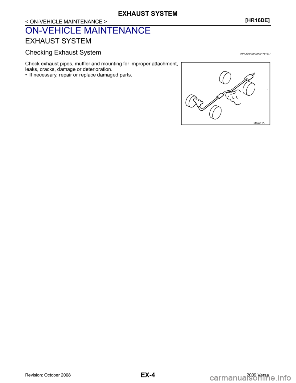
EXHAUST SYSTEM ....................................... .....4
Checking Exhaust System .................................. ......4
ON-VEHICLE REPAIR .... ..............................5 EXHAUST SYSTEM
........................................... 5
Component .......................................................... .....5
Removal and Installation ..................................... .....5
MR18DE
SERVICE INFORMATION .. ..........................7
PRECAUTIONS .................................................. 7
Precaution for Supplemental Restraint System
(SRS) "AIR BAG" and "SEAT BELT PRE-TEN-
SIONER" ............................................................. .....
7
Precaution Necessary for Steering Wheel Rota-
tion After Battery Disconnect ............................... .....
7
PREPARATION .................................................. 8
Special Service Tool ............................................ .....8
Commercial Service Tool .................................... .....8
EXHAUST SYSTEM ........................................... 9
Checking Exhaust System ................................... .....9
Component .......................................................... .....9
Removal and Installation ..................................... .....9
Page 3186 of 4331

Page 3187 of 4331
![NISSAN LATIO 2009 Service Repair Manual PREPARATION
EX-3
< PREPARATION >
[HR16DE] C
D E
F
G H
I
J
K L
M A EX
NP
O
PREPARATION
PREPARATION
Special Service Tool INFOID:0000000004784375
Commercial Service Tool INFOID:0000000004784394
Tool numb NISSAN LATIO 2009 Service Repair Manual PREPARATION
EX-3
< PREPARATION >
[HR16DE] C
D E
F
G H
I
J
K L
M A EX
NP
O
PREPARATION
PREPARATION
Special Service Tool INFOID:0000000004784375
Commercial Service Tool INFOID:0000000004784394
Tool numb](/img/5/57359/w960_57359-3186.png)
PREPARATION
EX-3
< PREPARATION >
[HR16DE] C
D E
F
G H
I
J
K L
M A EX
NP
O
PREPARATION
PREPARATION
Special Service Tool INFOID:0000000004784375
Commercial Service Tool INFOID:0000000004784394
Tool number
Tool name Description
KV10114400
(J-38365)
Heated oxygen sensor wrench Loosening or tightening heated oxygen sen-
sor
a: 22 mm (0.87 in) NT636
(Kent-Moore No.)
Tool name Description
(J-43897-18)
(J-43897-12)
Heated oxygen sensor thread cleaner Reconditioning the exhaust system threads
before installing new heated oxygen and Air
fuel ratio sensors (Use with anti-seize lubri-
cant shown below.)
a: 18 mm (0.71 in) dia. for zirconia heated
oxygen sensor
b: 12 mm (0.47 in) dia. for titania heated ox-
ygen sensor
Anti-seize lubricant (Permatex 133AR
or equivalent meeting MIL specifica-
tion MIL-A-907) Lubricating heated oxygen sensor thread
cleaner when reconditioning exhaust system
threads
Power tool Loosening bolts and nuts AEM488
AEM489
PBIC0190E
Page 3188 of 4331

Page 3189 of 4331

EX
NP
O
ON-VEHICLE REPAIR
EXHAUST SYSTEM
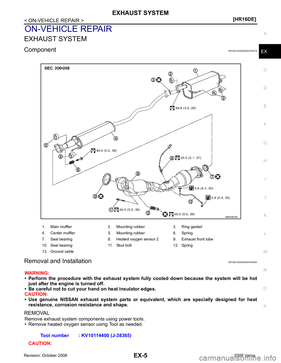
Component INFOID:0000000004784378
Removal and Installation INFOID:0000000004784393
WARNING:
• Perform the procedure with the exhaust system fu lly cooled down because the system will be hot
just after the engine is turned off.
• Be careful not to cut your hand on heat insulator edges.
CAUTION:
• Use genuine NISSAN exhaust system parts or equi valent, which are specially designed for heat
resistance, corrosion resistance and shape.
REMOVAL Remove exhaust system components using power tools.
• Remove heated oxygen sensor using Tool as needed.
CAUTION: 1. Main muffler 2. Mounting rubber 3. Ring gasket
4. Center muffler 5. Mounting rubber 6. Spring
7. Seal bearing 8. Heated oxygen sensor 2 9. Exhaust front tube
10. Seal bearing 11. Stud bolt 12. Spring
13. Ground cable
Page 3190 of 4331
