lock NISSAN NAVARA 2005 Repair Owners Manual
[x] Cancel search | Manufacturer: NISSAN, Model Year: 2005, Model line: NAVARA, Model: NISSAN NAVARA 2005Pages: 3171, PDF Size: 49.59 MB
Page 593 of 3171
SQUEAK AND RATTLE TROUBLE DIAGNOSES
BL-9
C
D
E
F
G
H
J
K
L
MA
B
BL
TRUNK
Trunk noises are often caused by a loose jack or loose items put into the trunk by the owner.
In addition look for:
1. Trunk lid dumpers out of adjustment
2. Trunk lid striker out of adjustment
3. Trunk lid torsion bars knocking together
4. A loose license plate or bracket
Most of these incidents can be repaired by adjusting, securing or insulating the item(s) or component(s) caus-
ing the noise.
SUNROOF/HEADLINING
Noises in the sunroof/headlining area can often be traced to one of the following:
1. Sunroof lid, rail, linkage or seals making a rattle or light knocking noise
2. Sunvisor shaft shaking in the holder
3. Front or rear windshield touching headlining and squeaking
Again, pressing on the components to stop the noise while duplicating the conditions can isolate most of these
incidents. Repairs usually consist of insulating with felt cloth tape.
SEATS
When isolating seat noise it's important to note the position the seat is in and the load placed on the seat when
the noise is present. These conditions should be duplicated when verifying and isolating the cause of the
noise.
Cause of seat noise include:
1. Headrest rods and holder
2. A squeak between the seat pad cushion and frame
3. Rear seatback lock and bracket
These noises can be isolated by moving or pressing on the suspected components while duplicating the con-
ditions under which the noise occurs. Most of these incidents can be repaired by repositioning the component
or applying urethane tape to the contact area.
UNDERHOOD
Some interior noise may be caused by components under the hood or on the engine wall. The noise is then
transmitted into the passenger compartment.
Causes of transmitted underhood noise include:
1. Any component mounted to the engine wall
2. Components that pass through the engine wall
3. Engine wall mounts and connectors
4. Loose radiator mounting pins
5. Hood bumpers out of adjustment
6. Hood striker out of adjustment
These noises can be difficult to isolate since they cannot be reached from the interior of the vehicle. The best
method is to secure, move or insulate one component at a time and test drive the vehicle. Also, engine RPM
or load can be changed to isolate the noise. Repairs can usually be made by moving, adjusting, securing, or
insulating the component causing the noise.
Page 597 of 3171
HOOD
BL-13
C
D
E
F
G
H
J
K
L
MA
B
BL
LONGITUDINAL AND LATERAL CLEARANCE ADJUSTMENT
1. Remove the hood lock, loosen the hood hinge nuts and close the hood.
2. Adjust the lateral and longitudinal clearance, and open the hood to tighten the mounting bolts to the spec-
ified torque.
3. Install the hood lock temporarily, and align the hood striker and lock so that the centers of striker and lock
become vertical viewed from the front, by moving the hood lock laterally.
4. Tighten hood lock mounting bolts to the specified torque.
FRONT END HEIGHT ADJUSTMENT
1. Remove the hood lock and adjust the height by rotating the bumper rubber until the hood becomes 1 to1.5
mm (0.04 to 0.059 in) lower than the fender.
2. Temporarily tighten the hood lock, and position it by engaging it with the hood striker. Check the lock and
striker for looseness, and tighten the hood lock mounting bolts to the specified torque.
CAUTION:
Adjust right/left clearance between hood and each part to the following specification.
SURFACE HEIGHT ADJUSTMENT
1. Remove the hood lock, and adjust the surface height difference of hood, fender and headlamp according
to the fitting standard dimension, by rotating RH and LH bumper rubbers.
2. Install hood lock temporarily, and move hood lock laterally until the centers of striker and lock become ver-
tical when viewed from the front.
3. Check that the hood lock secondary latch is properly engaged with the secondary striker with hood's own
weight.
4. Check that the hood lock primary latch is securely engaged with the hood striker with hood's own weight
by dropping hood from approx. 200 mm (7.87) height.
CAUTION:
Do not drop hood from a height of 300 mm (11.81 in) or more.
5. Move hood lockup and down until striker smoothly engages the lock when the hood is closed.
6. When pulling the hood opener lever gently, make sure that front end of the hood rises by approximately 20
mm (0.79) and that hood striker and hood lock primary latch is disengaged. Also make sure that hood
opener returns to the original position.
7. After adjustment, tighten lock bolts to the specified torque.
CAUTION:
lAfter installing, apply touch-up paint (the body color) onto the head of the hinge mounting nuts.
lAdjust evenness between hood and each part to the following specification.
Portion Clearance
Hood - Front grille A - A (a) 3.7 - 8.3 mm (0.146 - 0.327 in)
Hood - Front fender B - B (c) 3.6 - 5.6 mm (0.142 - 0.220 in)
Hood - Headlamp C - C (e) 6.0 - 8.0 mm (0.236 - 0.315 in)
Portion R / L difference
Hood - Front grille A - A (a) Less than 2.2 mm (0.087 in)
Hood - Front fender B - B (c) Less than 1.0 mm (0.039 In)
Portion Surface height
Hood - Front grille A - A (b) -1.7 - 3.1 mm (-0.067 - 0.122 in)
Hood - Front fender B - B (d) -1.0 - 1.0 mm (-0.039 - 0.039 in)
Hood - Headlamp C - C (f) -1.3 - 2.7 mm (-0.051 - 0.106 in)
Page 599 of 3171
HOOD
BL-15
C
D
E
F
G
H
J
K
L
MA
B
BL
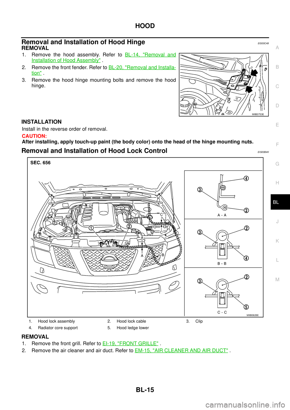
Removal and Installation of Hood HingeEIS00C49
REMOVAL
1. Remove the hood assembly. Refer toBL-14, "Removal and
Installation of Hood Assembly".
2. Remove the front fender. Refer toBL-20, "
Removal and Installa-
tion".
3. Remove the hood hinge mounting bolts and remove the hood
hinge.
INSTALLATION
Install in the reverse order of removal.
CAUTION:
After installing, apply touch-up paint (the body color) onto the head of the hinge mounting nuts.
Removal and Installation of Hood Lock ControlEIS00B4K
REMOVAL
1. Remove the front grill. Refer toEI-19, "FRONT GRILLE".
2. Remove the air cleaner and air duct. Refer toEM-15, "
AIR CLEANER AND AIR DUCT".
MIIB0753E
1. Hood lock assembly 2. Hood lock cable 3. Clip
4. Radiator core support 5. Hood ledge lower
MIIB0628E
Page 600 of 3171
BL-16
HOOD
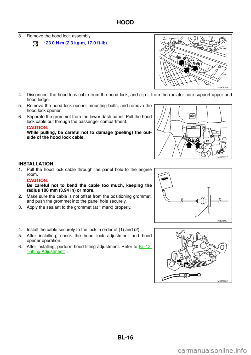
3. Remove the hood lock assembly.
4. Disconnect the hood lock cable from the hood lock, and clip it from the radiator core support upper and
hood ledge.
5. Remove the hood lock opener mounting bolts, and remove the
hood lock opener.
6. Separate the grommet from the lower dash panel. Pull the hood
lock cable out through the passenger compartment.
CAUTION:
While pulling, be careful not to damage (peeling) the out-
side of the hood lock cable.
INSTALLATION
1. Pull the hood lock cable through the panel hole to the engine
room.
CAUTION:
Be careful not to bend the cable too much, keeping the
radius 100 mm (3.94 in) or more.
2. Make sure the cable is not offset from the positioning grommet,
and push the grommet into the panel hole securely.
3. Apply the sealant to the grommet (at * mark) properly.
4. Install the cable securely to the lock in order of (1) and (2).
5. After installing, check the hood lock adjustment and hood
opener operation.
6. After installing, perform hood fitting adjustment. Refer toBL-12,
"Fitting Adjustment". : 23.0 N·m (2.3 kg-m, 17.0 ft-lb)
MIIB0629E
MIIB0657E
PIIB2909J
MIIB0638E
Page 601 of 3171
HOOD
BL-17
C
D
E
F
G
H
J
K
L
MA
B
BL
Hood Lock Control InspectionEIS00BQ1
CAUTION:
If the hood lock cable is bent or deformed, replace it.
1. Make sure that the hood lock secondary latch is properly engaged with the secondary striker with hood's
own weight.
2. Make sure that the hood lock primary latch is securely engaged with the hood striker with hood's own
weight by dropping it from approx. 200 mm (7.87 in) height.
CAUTION:
Do not drop hood from a height of 300 mm (11.81 in) or more.
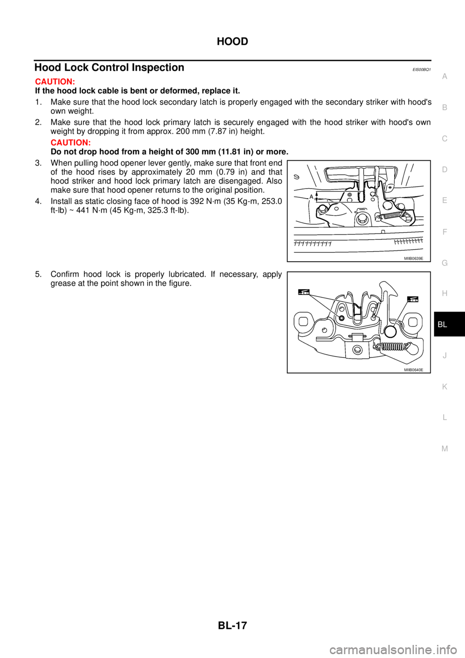
3. When pulling hood opener lever gently, make sure that front end
of the hood rises by approximately 20 mm (0.79 in) and that
hood striker and hood lock primary latch are disengaged. Also
make sure that hood opener returns to the original position.
4. Install as static closing face of hood is 392 N·m (35 Kg-m, 253.0
ft-lb) ~ 441 N·m (45 Kg-m, 325.3 ft-lb).
5. Confirm hood lock is properly lubricated. If necessary, apply
grease at the point shown in the figure.
MIIB0639E
MIIB0640E
Page 602 of 3171
BL-18
RADIATOR CORE SUPPORT
RADIATOR CORE SUPPORT
PFP:62500
Removal and InstallationEIS00DGJ
REMOVAL
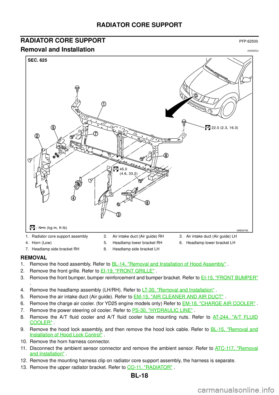
1. Remove the hood assembly. Refer toBL-14, "Removal and Installation of Hood Assembly".
2. Remove the front grille. Refer toEI-19, "
FRONT GRILLE".
3. Remove the front bumper, bumper reinforcement and bumper bracket. Refer toEI-15, "
FRONT BUMPER"
.
4. Remove the headlamp assembly (LH/RH). Refer toLT-30, "
Removal and Installation".
5. Remove the air intake duct (Air guide). Refer toEM-15, "
AIR CLEANER AND AIR DUCT".
6. Remove the charge air cooler. (for YD25 engine models only) Refer toEM-18, "
CHARGE AIR COOLER".
7. Remove the power steering oil cooler. Refer toPS-30, "
HYDRAULIC LINE".
8. Remove the A/T fluid cooler and A/T fluid cooler tube mounting nuts. Refer toAT- 2 4 4 , "
A/T FLUID
COOLER".
9. Remove the hood lock assembly, and then remove the hood lock cable. Refer toBL-15, "
Removal and
Installation of Hood Lock Control".
10. Remove the horn harness connector.
11. Disconnect the ambient sensor connector and remove the ambient sensor. Refer toAT C - 11 7 , "
Removal
and Installation".
12. Remove the mounting harness clip on radiator core support assembly, the harness is separate.
13. Remove the upper radiator bracket. Refer toCO-11, "
RADIATOR".
1. Radiator core support assembly 2. Air intake duct (Air guide) RH 3. Air intake duct (Air guide) LH
4. Horn (Low) 5. Headlamp lower bracket RH 6. Headlamp lower bracket LH
7. Headlamp side bracket RH 8. Headlamp side bracket LH
MIIB0979E
Page 603 of 3171
RADIATOR CORE SUPPORT
BL-19
C
D
E
F
G
H
J
K
L
MA
B
BL
14. Remove the radiator core support mounting bolts and remove the radiator core support assembly.
15. After removing the radiator core support assembly, the following parts are separate.
lHorn (Low).
lHeadlamp side bracket (LH/RH).
lHeadlamp lower bracket (LH/RH).
INSTALLATION
Install in the reverse order of removal.
CAUTION:
After installing, check the hood adjustment and hood opener operation. Refer toBL-12, "
Fitting
Adjustment"andBL-17, "Hood Lock Control Inspection".
Page 605 of 3171
POWERDOORLOCKSYSTEM
BL-21
C
D
E
F
G
H
J
K
L
MA
B
BL
POWER DOOR LOCK SYSTEMPFP:24814
Component Parts and Harness Connector LocationEIS00D7Q
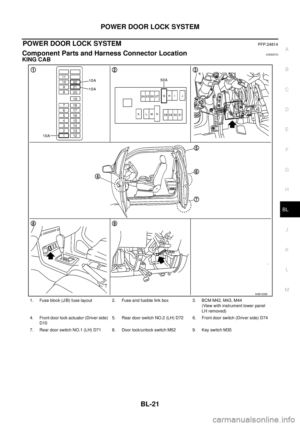
KING CAB
1. Fuse block (J/B) fuse layout 2. Fuse and fusible link box 3. BCM M42, M43, M44
(View with instrument lower panel
LH removed)
4. Front door lock actuator (Driver side)
D105. Rear door switch NO.2 (LH) D72 6. Front door switch (Driver side) D74
7. Rear door switch NO.1 (LH) D71 8. Door lock/unlock switch M52 9. Key switch M35
MIIB1028E
Page 606 of 3171
BL-22
POWER DOOR LOCK SYSTEM
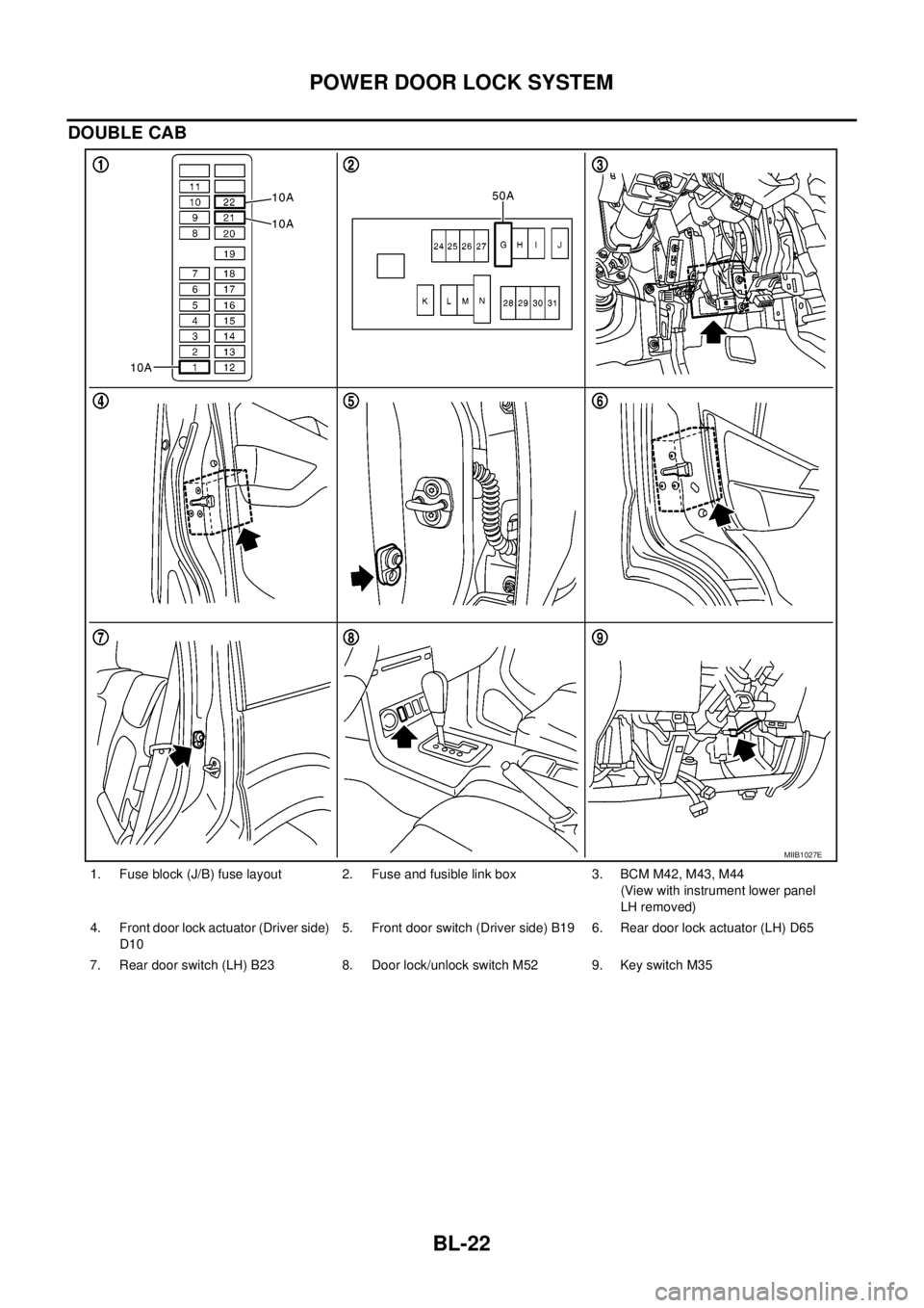
DOUBLE CAB
1. Fuse block (J/B) fuse layout 2. Fuse and fusible link box 3. BCM M42, M43, M44
(View with instrument lower panel
LH removed)
4. Front door lock actuator (Driver side)
D105. Front door switch (Driver side) B19 6. Rear door lock actuator (LH) D65
7. Rear door switch (LH) B23 8. Door lock/unlock switch M52 9. Key switch M35
MIIB1027E
Page 607 of 3171
POWERDOORLOCKSYSTEM
BL-23
C
D
E
F
G
H
J
K
L
MA
B
BL
System DescriptionEIS00D7R
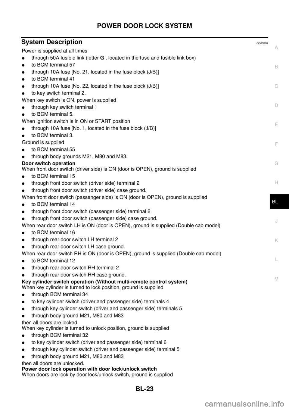
Power is supplied at all times
lthrough 50A fusible link (letterG, located in the fuse and fusible link box)
lto BCM terminal 57
lthrough 10A fuse [No. 21, located in the fuse block (J/B)]
lto BCM terminal 41
lthrough 10A fuse [No. 22, located in the fuse block (J/B)]
lto key switch terminal 2.
When key switch is ON, power is supplied
lthrough key switch terminal 1
lto BCM terminal 5.
When ignition switch is in ON or START position
lthrough 10A fuse [No. 1, located in the fuse block (J/B)]
lto BCM terminal 3.
Ground is supplied
lto BCM terminal 55
lthrough body grounds M21, M80 and M83.
Door switch operation
When front door switch (driver side) is ON (door is OPEN), ground is supplied
lto BCM terminal 15
lthrough front door switch (driver side) terminal 2
lthrough front door switch (driver side) case ground.
When front door switch (passenger side) is ON (door is OPEN), ground is supplied
lto BCM terminal 14
lthrough front door switch (passenger side) terminal 2
lthrough front door switch (passenger side) case ground.
When rear door switch LH is ON (door is OPEN), ground is supplied (Double cab model)
lto BCM terminal 16
lthrough rear door switch LH terminal 2
lthrough rear door switch LH case ground.
When rear door switch RH is ON (door is OPEN), ground is supplied (Double cab model)
lto BCM terminal 12
lthrough rear door switch RH terminal 2
lthrough rear door switch RH case ground.
Key cylinder switch operation (Without multi-remote control system)
When key cylinder is turned to lock position, ground is supplied
lthrough BCM terminal 34
lto key cylinder switch (driver and passenger side) terminals 4
lthrough key cylinder switch (driver and passenger side) terminals 5
lthrough body ground M21, M80 and M83
then all doors are locked.
When key cylinder is turned to unlock position, ground is supplied
lthrough BCM terminal 32
lto key cylinder switch (driver and passenger side) terminal 6
lthrough key cylinder switch (driver and passenger side) terminal 5
lthrough body ground M21, M80 and M83
then all doors are unlocked.
Power door lock operation with door lock/unlock switch
When doors are lock by door lock/unlock switch, ground is supplied