NISSAN NAVARA 2005 Repair Workshop Manual
Manufacturer: NISSAN, Model Year: 2005, Model line: NAVARA, Model: NISSAN NAVARA 2005Pages: 3171, PDF Size: 49.59 MB
Page 1251 of 3171

DTC P1622 INJECTOR ADJUSTMENT VALUE
EC-271
C
D
E
F
G
H
I
J
K
L
MA
EC
DTC P1622 INJECTOR ADJUSTMENT VALUEPFP:23710
DescriptionEBS01KKL
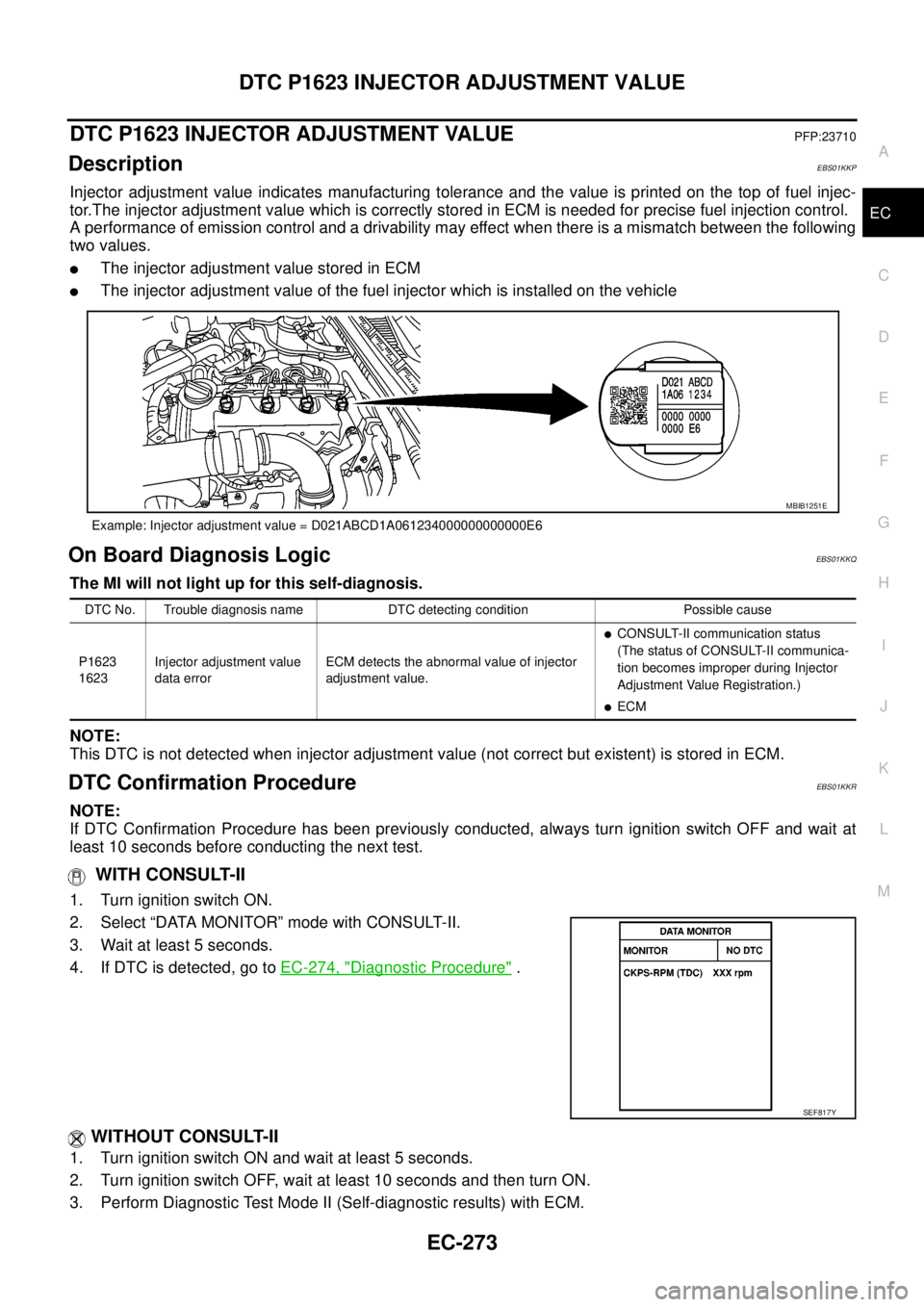
Injector adjustment value indicates manufacturing tolerance and the value is printed on the top of fuel injec-
tor.The injector adjustment value which is correctly stored in ECM is needed for precise fuel injection control.
A performance of emission control and a drivability may effect when there is a mismatch between the following
two values.
lThe injector adjustment value stored in ECM
lThe injector adjustment value of the fuel injector which is installed on the vehicle
On Board Diagnosis LogicEBS01KKM
The MI will not light up for this self-diagnosis.
DTC Confirmation ProcedureEBS01KKN
NOTE:
If DTC Confirmation Procedure has been previously conducted, always turn ignition switch OFF and wait at
least 10 seconds before conducting the next test.
WITH CONSULT-II
1. Turn ignition switch ON.
2. Select “DATA MONITOR” mode with CONSULT-II.
3. Wait at least 5 seconds.
4. If DTC is detected, go toEC-272, "
Diagnostic Procedure".
WITHOUT CONSULT-II
1. Turn ignition switch ON and wait at least 5 seconds.
2. Turn ignition switch OFF, wait at least 10 seconds and then turn ON.
3. Perform Diagnostic Test Mode II (Self-diagnostic results) with ECM.
4. If DTC is detected, go toEC-272, "
Diagnostic Procedure".
Example: Injector adjustment value = D021ABCD1A061234000000000000E6
MBIB1251E
DTC No. Trouble diagnosis name DTC detecting condition Possible cause
P1622
1622Injector adjustment value
data uninputInjector adjustment value is not stored in ECM.
lInjector adjustment value
(Injector adjustment value has not
been written onto ECM memory yet,
or the value has been initialized.)
SEF817Y
Page 1252 of 3171

EC-272
DTC P1622 INJECTOR ADJUSTMENT VALUE
Diagnostic Procedure
EBS01KKO
1.PERFORM INJECTOR ADJUSTMENT VALUE REGISTRATION
Perform Injector Adjustment Value Registration. Refer toEC-25, "
Injector Adjustment Value Registration".
>>INSPECTION END
Page 1253 of 3171
DTC P1623 INJECTOR ADJUSTMENT VALUE
EC-273
C
D
E
F
G
H
I
J
K
L
MA
EC
DTC P1623 INJECTOR ADJUSTMENT VALUEPFP:23710
DescriptionEBS01KKP
Injector adjustment value indicates manufacturing tolerance and the value is printed on the top of fuel injec-
tor.The injector adjustment value which is correctly stored in ECM is needed for precise fuel injection control.
A performance of emission control and a drivability may effect when there is a mismatch between the following
two values.
lThe injector adjustment value stored in ECM
lThe injector adjustment value of the fuel injector which is installed on the vehicle
On Board Diagnosis LogicEBS01KKQ
The MI will not light up for this self-diagnosis.
NOTE:
This DTC is not detected when injector adjustment value (not correct but existent) is stored in ECM.
DTC Confirmation ProcedureEBS01KKR
NOTE:
If DTC Confirmation Procedure has been previously conducted, always turn ignition switch OFF and wait at
least 10 seconds before conducting the next test.
WITH CONSULT-II
1. Turn ignition switch ON.
2. Select “DATA MONITOR” mode with CONSULT-II.
3. Wait at least 5 seconds.
4. If DTC is detected, go toEC-274, "
Diagnostic Procedure".
WITHOUT CONSULT-II
1. Turn ignition switch ON and wait at least 5 seconds.
2. Turn ignition switch OFF, wait at least 10 seconds and then turn ON.
3. Perform Diagnostic Test Mode II (Self-diagnostic results) with ECM.
Example: Injector adjustment value = D021ABCD1A061234000000000000E6
MBIB1251E
DTC No. Trouble diagnosis name DTC detecting condition Possible cause
P1623
1623Injector adjustment value
data errorECM detects the abnormal value of injector
adjustment value.
lCONSULT-II communication status
(The status of CONSULT-II communica-
tion becomes improper during Injector
Adjustment Value Registration.)
lECM
SEF817Y
Page 1254 of 3171
EC-274
DTC P1623 INJECTOR ADJUSTMENT VALUE
4. If DTC is detected, go toEC-274, "Diagnostic Procedure".
Diagnostic ProcedureEBS01KKS
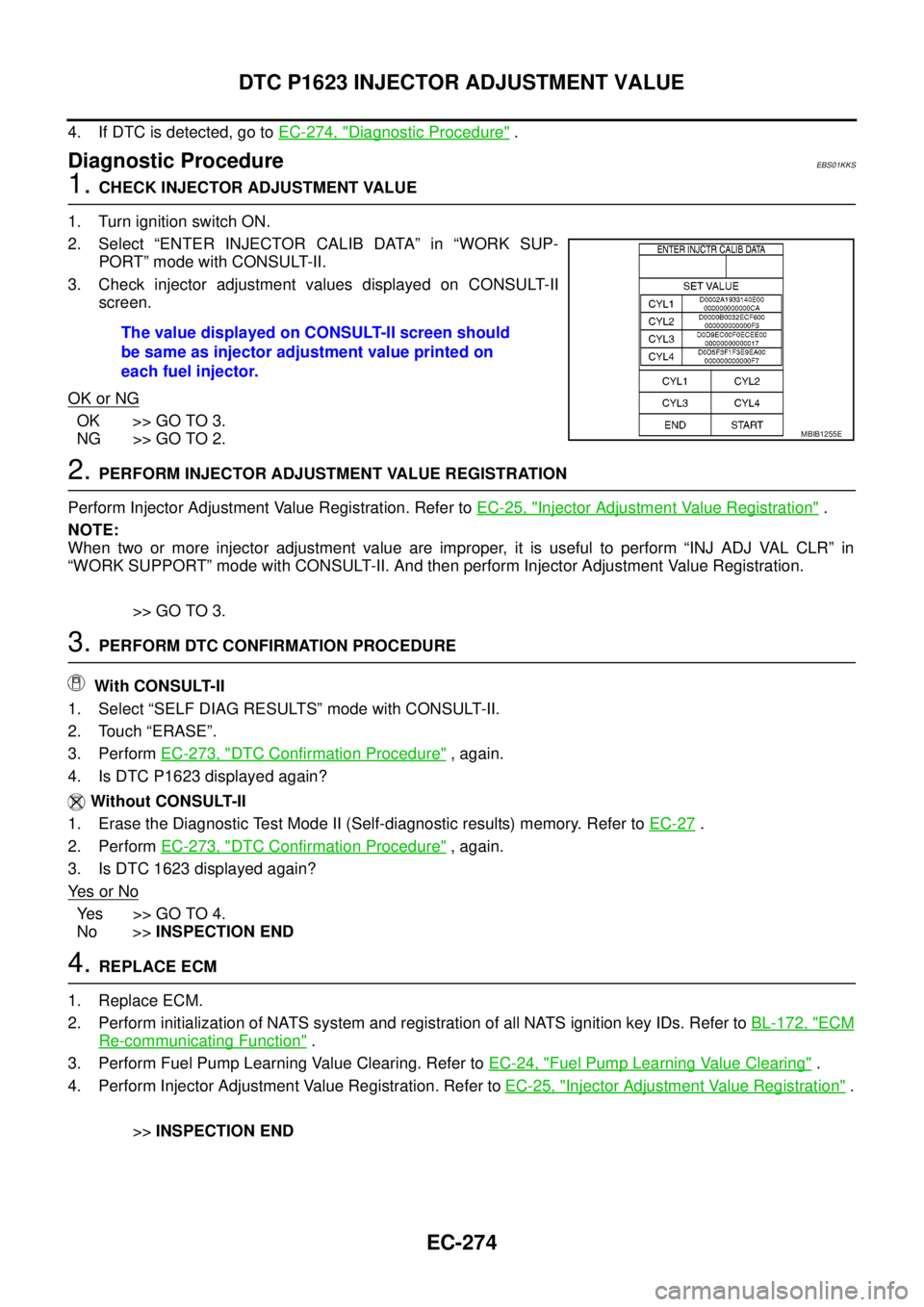
1.CHECK INJECTOR ADJUSTMENT VALUE
1. Turn ignition switch ON.
2. Select “ENTER INJECTOR CALIB DATA” in “WORK SUP-
PORT” mode with CONSULT-II.
3. Check injector adjustment values displayed on CONSULT-II
screen.
OK or NG
OK >> GO TO 3.
NG >> GO TO 2.
2.PERFORM INJECTOR ADJUSTMENT VALUE REGISTRATION
Perform Injector Adjustment Value Registration. Refer toEC-25, "
Injector Adjustment Value Registration".
NOTE:
When two or more injector adjustment value are improper, it is useful to perform “INJ ADJ VAL CLR” in
“WORK SUPPORT” mode with CONSULT-II. And then perform Injector Adjustment Value Registration.
>> GO TO 3.
3.PERFORM DTC CONFIRMATION PROCEDURE
With CONSULT-II
1. Select “SELF DIAG RESULTS” mode with CONSULT-II.
2. Touch “ERASE”.
3. PerformEC-273, "
DTC Confirmation Procedure",again.
4. Is DTC P1623 displayed again?
Without CONSULT-II
1. Erase the Diagnostic Test Mode II (Self-diagnostic results) memory. Refer toEC-27
.
2. PerformEC-273, "
DTC Confirmation Procedure",again.
3. Is DTC 1623 displayed again?
Ye s o r N o
Yes >>GOTO4.
No >>INSPECTION END
4.REPLACE ECM
1. Replace ECM.
2. Perform initialization of NATS system and registration of all NATS ignition key IDs. Refer toBL-172, "
ECM
Re-communicating Function".
3. Perform Fuel Pump Learning Value Clearing. Refer toEC-24, "
Fuel Pump Learning Value Clearing".
4. Perform Injector Adjustment Value Registration. Refer toEC-25, "
Injector Adjustment Value Registration".
>>INSPECTION END The value displayed on CONSULT-II screen should
be same as injector adjustment value printed on
each fuel injector.
MBIB1255E
Page 1255 of 3171
DTC P2135 APP SENSOR
EC-275
C
D
E
F
G
H
I
J
K
L
MA
EC
DTC P2135 APP SENSORPFP:18002
DescriptionEBS01KKT
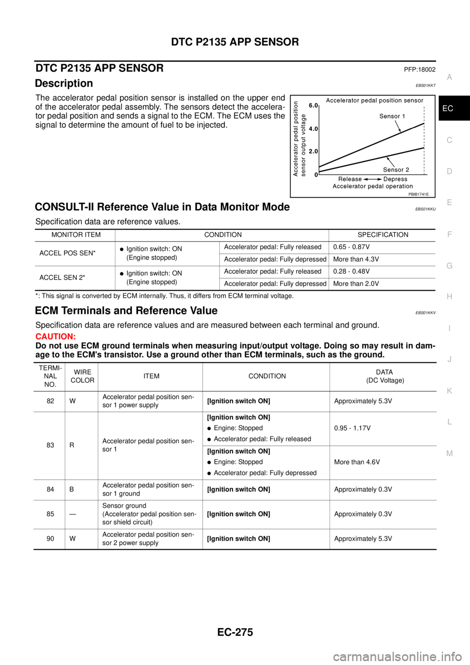
The accelerator pedal position sensor is installed on the upper end
of the accelerator pedal assembly. The sensors detect the accelera-
tor pedal position and sends a signal to the ECM. The ECM uses the
signal to determine the amount of fuel to be injected.
CONSULT-II Reference Value in Data Monitor ModeEBS01KKU
Specification data are reference values.
*: This signal is converted by ECM internally. Thus, it differs from ECM terminal voltage.
ECM Terminals and Reference ValueEBS01KKV
Specification data are reference values and are measured between each terminal and ground.
CAUTION:
Do not use ECM ground terminals when measuring input/output voltage. Doing so may result in dam-
age to the ECM's transistor. Use a ground other than ECM terminals, such as the ground.
PBIB1741E
MONITOR ITEM CONDITION SPECIFICATION
ACCEL POS SEN*
lIgnition switch: ON
(Engine stopped)Accelerator pedal: Fully released 0.65 - 0.87V
Accelerator pedal: Fully depressed More than 4.3V
ACCEL SEN 2*
lIgnition switch: ON
(Engine stopped)Accelerator pedal: Fully released 0.28 - 0.48V
Accelerator pedal: Fully depressed More than 2.0V
TERMI-
NAL
NO.WIRE
COLORITEM CONDITIONDATA
(DC Voltage)
82 WAccelerator pedal position sen-
sor 1 power supply[Ignition switch ON]Approximately 5.3V
83 RAccelerator pedal position sen-
sor 1[Ignition switch ON]
lEngine: Stopped
lAccelerator pedal: Fully released0.95 - 1.17V
[Ignition switch ON]
lEngine: Stopped
lAccelerator pedal: Fully depressedMore than 4.6V
84 BAccelerator pedal position sen-
sor 1 ground[Ignition switch ON]Approximately 0.3V
85 —Sensor ground
(Accelerator pedal position sen-
sor shield circuit)[Ignition switch ON]Approximately 0.3V
90 WAccelerator pedal position sen-
sor 2 power supply[Ignition switch ON]Approximately 5.3V
Page 1256 of 3171
EC-276
DTC P2135 APP SENSOR
On Board Diagnosis Logic
EBS01KKW
The MI will not light up for this self-diagnosis.
NOTE:
lIf DTC P2135 is displayed with DTC P0642 or P0643, first perform the trouble diagnosis for DTC
P0642 or P0643. Refer toEC-222, "
DTC P0642, P0643 SENSOR POWER SUPPLY".
lIf DTC P2135 is displayed with DTC P0652 or P0653, first perform the trouble diagnosis for DTC
P0652 or P0653. Refer toEC-227, "
DTC P0652, P0653 SENSOR POWER SUPPLY".
DTC Confirmation ProcedureEBS01KKX
NOTE:
If DTC Confirmation Procedure has been previously conducted, always turn ignition switch OFF and wait at
least 10 seconds before conducting the next test.
WITH CONSULT-II
1. Turn ignition switch ON.
2. Select “DATA MONITOR” mode with CONSULT-II.
3. Wait at least 5 seconds.
4. Depress accelerator pedal slowly spending 5 seconds, and then
release it slowly spending 5 seconds.
5. If DTC is detected, go toEC-278, "
Diagnostic Procedure".
WITHOUT CONSULT-II
1. Turn ignition switch ON and wait at least 5 seconds.
2. Depress accelerator pedal slowly spending 5 seconds, and then release it slowly spending 5 seconds.
3. Turn ignition switch OFF, wait at least 10 seconds and then turn ON.
4. Perform Diagnostic Test Mode II (Self-diagnostic results) with ECM.
5. If DTC is detected, go toEC-278, "
Diagnostic Procedure".
91 RAccelerator pedal position sen-
sor 2[Ignition switch ON]
lEngine: Stopped
lAccelerator pedal: Fully released0.58 - 0.78V
[Ignition switch ON]
lEngine: Stopped
lAccelerator pedal: Fully depressedMore than 2.3V
92 BAccelerator pedal position sen-
sor 2 ground[Ignition switch ON]Approximately 0.3V TERMI-
NAL
NO.WIRE
COLORITEM CONDITIONDATA
(DC Voltage)
DTC No. Trouble diagnosis name DTC detecting condition Possible cause
P2135
2135Accelerator pedal position
sensor 1, 2 signal correla-
tionThe correlation between APP sensor 1 signal
and APP sensor 2 signal is out of the normal
range.
lHarness or connectors
(The APP sensor circuit is open or
shorted.)
lAccelerator pedal position sensor
SEF817Y
Page 1257 of 3171
DTC P2135 APP SENSOR
EC-277
C
D
E
F
G
H
I
J
K
L
MA
EC
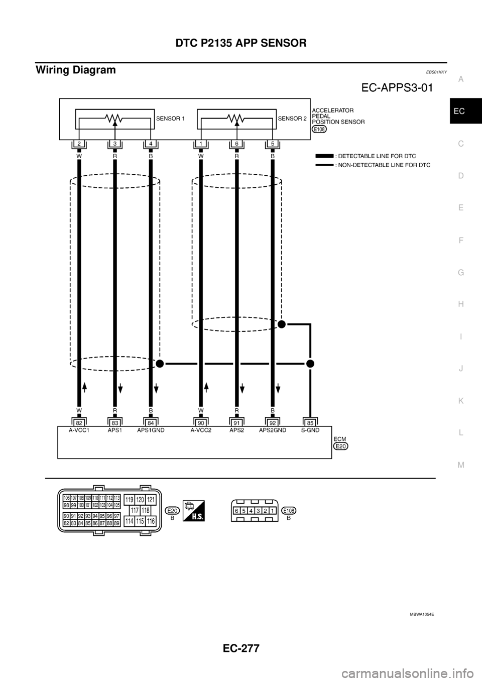
Wiring DiagramEBS01KKY
MBWA1054E
Page 1258 of 3171
EC-278
DTC P2135 APP SENSOR
Diagnostic Procedure
EBS01KKZ
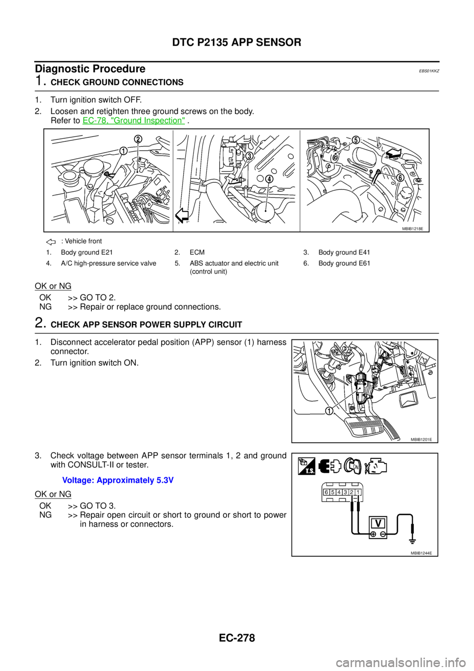
1.CHECK GROUND CONNECTIONS
1. Turn ignition switch OFF.
2. Loosen and retighten three ground screws on the body.
Refer toEC-78, "
Ground Inspection".
OK or NG
OK >> GO TO 2.
NG >> Repair or replace ground connections.
2.CHECK APP SENSOR POWER SUPPLY CIRCUIT
1. Disconnect accelerator pedal position (APP) sensor (1) harness
connector.
2. Turn ignition switch ON.
3. Check voltage between APP sensor terminals 1, 2 and ground
with CONSULT-II or tester.
OK or NG
OK >> GO TO 3.
NG >> Repair open circuit or short to ground or short to power
in harness or connectors.
: Vehicle front
1. Body ground E21 2. ECM 3. Body ground E41
4. A/C high-pressure service valve 5. ABS actuator and electric unit
(control unit)6. Body ground E61
MBIB1218E
MBIB1201E
Voltage: Approximately 5.3V
MBIB1244E
Page 1259 of 3171
DTC P2135 APP SENSOR
EC-279
C
D
E
F
G
H
I
J
K
L
MA
EC
3.CHECK APP SENSOR GROUND CIRCUIT FOR OPEN AND SHORT
1. Turn ignition switch OFF.
2. Disconnect ECM harness connector.
3. Check harness continuity between APP sensor terminal 4 and ECM terminal 84, APP sensor terminal 5
and ECM terminal 92.
Refer to Wiring Diagram.
4. Also check harness for short to ground and short to power.
OK or NG
OK >> GO TO 4.
NG >> Repair open circuit or short to ground or short to power in harness or connectors.
4.CHECK APP SENSOR INPUT SIGNAL CIRCUIT FOR OPEN AND SHORT
1. Check harness continuity between ECM terminal 83 and APP sensor terminal 3, ECM terminal 91 and
APPsensorterminal6.
Refer to Wiring Diagram.
2. Also check harness for short to ground and short to power.
OK or NG
OK >> GO TO 5.
NG >> Repair open circuit or short to ground or short to power in harness or connectors.
5.CHECK APP SENSOR
Refer toEC-279, "
Component Inspection".
OK or NG
OK >> GO TO 6.
NG >> Replace accelerator pedal assembly.
6.CHECK INTERMITTENT INCIDENT
Refer toEC-70, "
TROUBLE DIAGNOSIS FOR INTERMITTENT INCIDENT".
>>INSPECTION END
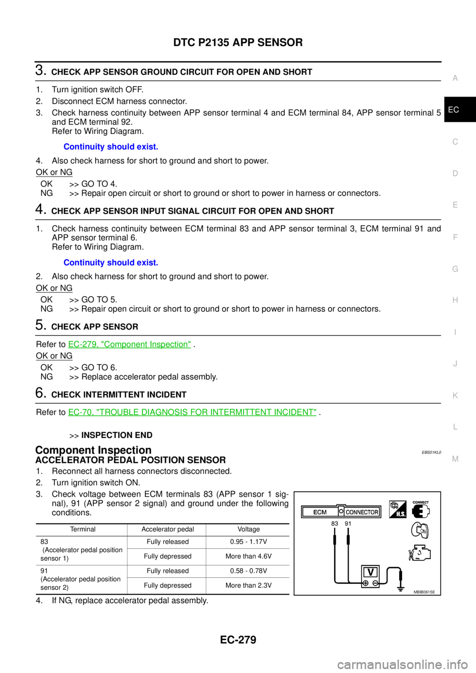
Component InspectionEBS01KL0
ACCELERATOR PEDAL POSITION SENSOR
1. Reconnect all harness connectors disconnected.
2. Turn ignition switch ON.
3. Check voltage between ECM terminals 83 (APP sensor 1 sig-
nal), 91 (APP sensor 2 signal) and ground under the following
conditions.
4. If NG, replace accelerator pedal assembly.Continuity should exist.
Continuity should exist.
Terminal Accelerator pedal Voltage
83
(Accelerator pedal position
sensor 1)Fully released 0.95 - 1.17V
Fully depressed More than 4.6V
91
(Accelerator pedal position
sensor 2)Fully released 0.58 - 0.78V
Fully depressed More than 2.3V
MBIB0615E
Page 1260 of 3171

EC-280
DTC P2135 APP SENSOR
Removal and Installation
EBS01KL1
ACCELERATOR PEDAL
Refer toACC-2, "ACCELERATOR CONTROL SYSTEM".