grease NISSAN NAVARA 2005 Repair User Guide
[x] Cancel search | Manufacturer: NISSAN, Model Year: 2005, Model line: NAVARA, Model: NISSAN NAVARA 2005Pages: 3171, PDF Size: 49.59 MB
Page 814 of 3171
BR-28
FRONT DISC BRAKE
ASSEMBLY
CAUTION:
When assembling, use only rubber lubricant specified below.
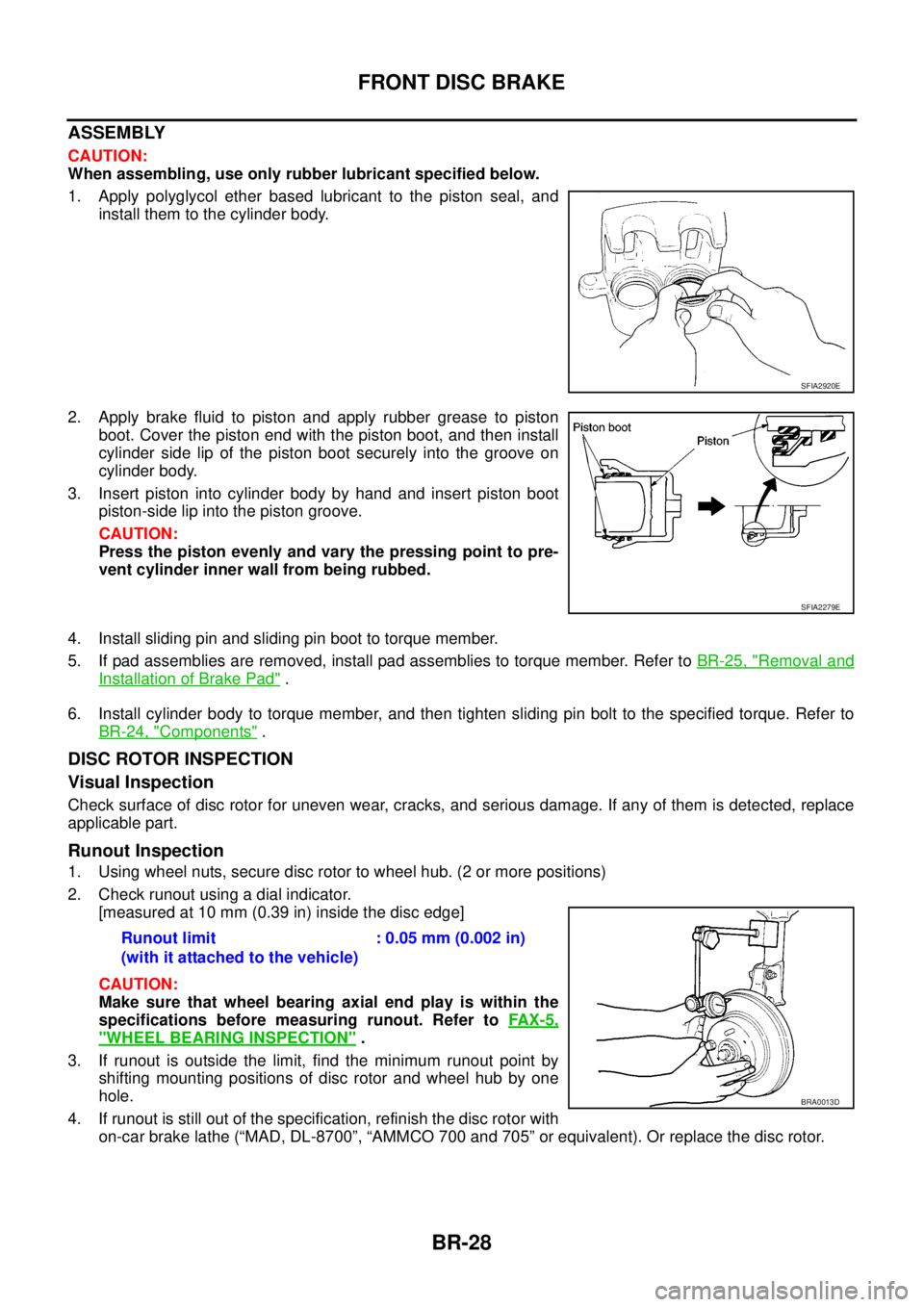
1. Apply polyglycol ether based lubricant to the piston seal, and
install them to the cylinder body.
2. Apply brake fluid to piston and apply rubber grease to piston
boot.Coverthepistonendwiththepistonboot,andtheninstall
cylinder side lip of the piston boot securely into the groove on
cylinder body.
3. Insert piston into cylinder body by hand and insert piston boot
piston-side lip into the piston groove.
CAUTION:
Press the piston evenly and vary the pressing point to pre-
vent cylinder inner wall from being rubbed.
4. Install sliding pin and sliding pin boot to torque member.
5. If pad assemblies are removed, install pad assemblies to torque member. Refer toBR-25, "
Removal and
Installation of Brake Pad".
6. Install cylinder body to torque member, and then tighten sliding pin bolt to the specified torque. Refer to
BR-24, "
Components".
DISC ROTOR INSPECTION
Visual Inspection
Check surface of disc rotor for uneven wear, cracks, and serious damage. If any of them is detected, replace
applicable part.
Runout Inspection
1. Using wheel nuts, secure disc rotor to wheel hub. (2 or more positions)
2. Check runout using a dial indicator.
[measured at 10 mm (0.39 in) inside the disc edge]
CAUTION:
Make sure that wheel bearing axial end play is within the
specifications before measuring runout. Refer toFAX-5,
"WHEEL BEARING INSPECTION".
3. If runout is outside the limit, find the minimum runout point by
shifting mounting positions of disc rotor and wheel hub by one
hole.
4. If runout is still out of the specification, refinish the disc rotor with
on-car brake lathe (“MAD, DL-8700”, “AMMCO 700 and 705” or equivalent). Or replace the disc rotor.
SFIA2920E
SFIA2279E
Runout limit
(with it attached to the vehicle):0.05mm(0.002in)
BRA0013D
Page 816 of 3171
BR-30
REAR DRUM BRAKE
REAR DRUM BRAKE
PFP:43206
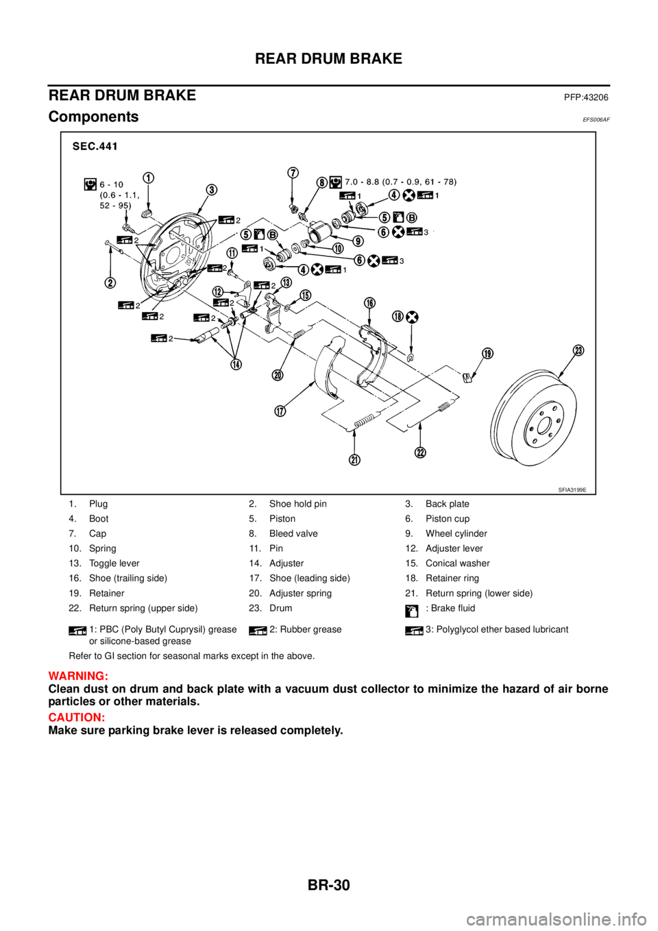
ComponentsEFS006AF
WARNING:
Clean dust on drum and back plate with a vacuum dust collector to minimize the hazard of air borne
particles or other materials.
CAUTION:
Make sure parking brake lever is released completely.
1. Plug 2. Shoe hold pin 3. Back plate
4. Boot 5. Piston 6. Piston cup
7. Cap 8. Bleed valve 9. Wheel cylinder
10. Spring 11. Pin 12. Adjuster lever
13. Toggle lever 14. Adjuster 15. Conical washer
16. Shoe (trailing side) 17. Shoe (leading side) 18. Retainer ring
19. Retainer 20. Adjuster spring 21. Return spring (lower side)
22. Return spring (upper side) 23. Drum : Brake fluid
1: PBC (Poly Butyl Cuprysil) grease
or silicone-based grease2: Rubber grease 3: Polyglycol ether based lubricant
Refer to GI section for seasonal marks except in the above.
SFIA3199E
Page 819 of 3171
REAR DRUM BRAKE
BR-33
C
D
E
G
H
I
J
K
L
MA
B
BR
INSTALLATION
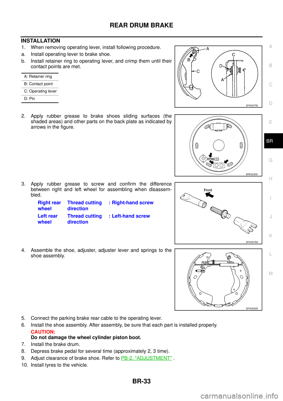
1. When removing operating lever, install following procedure.
a. Install operating lever to brake shoe.
b. Install retainer ring to operating lever, and crimp them until their
contact points are met.
2. Apply rubber grease to brake shoes sliding surfaces (the
shaded areas) and other parts on the back plate as indicated by
arrows in the figure.
3. Apply rubber grease to screw and confirm the difference
between right and left wheel for assembling when disassem-
bled.
4. Assemble the shoe, adjuster, adjuster lever and springs to the
shoe assembly.
5. Connect the parking brake rear cable to the operating lever.
6. Install the shoe assembly. After assembly, be sure that each part is installed properly.
CAUTION:
Do not damage the wheel cylinder piston boot.
7. Install the brake drum.
8. Depress brake pedal for several time (approximately 2, 3 time).
9. Adjust clearance of brake shoe. Refer toPB-2, "
ADJUSTMENT".
10. Install tyres to the vehicle.
A: Retainer ring
B: Contact point
C: Operating lever
D: Pin
SFIA3075E
BRE0220D
Right rear
wheelThread cutting
direction: Right-hand screw
Left rear
wheelThread cutting
direction: Left-hand screw
SFIA3076E
SFIA3202E
Page 820 of 3171
BR-34
REAR DRUM BRAKE
Removal and Installation of Wheel Cylinder
EFS006AH
REMOVAL
1. Drain brake fluid. Refer toBR-10, "Drain and Refill".
2. Remove rear brake shoe assembly.
3. Remove brake tube from the wheel cylinder.
4. Remove bolts on the wheel cylinder, and then remove wheel cylinder from the back plate.
INSTALLATION
lInstallation is the reverse order of removal. Tighten bolts to the specified torque. Refer toBR-30, "Compo-
nents".
lRefill with new brake fluid and bleed air. Refer toBR-11, "Bleeding Brake System".
Disassembly and Assembly of Wheel CylinderEFS006AI
DISASSEMBLY
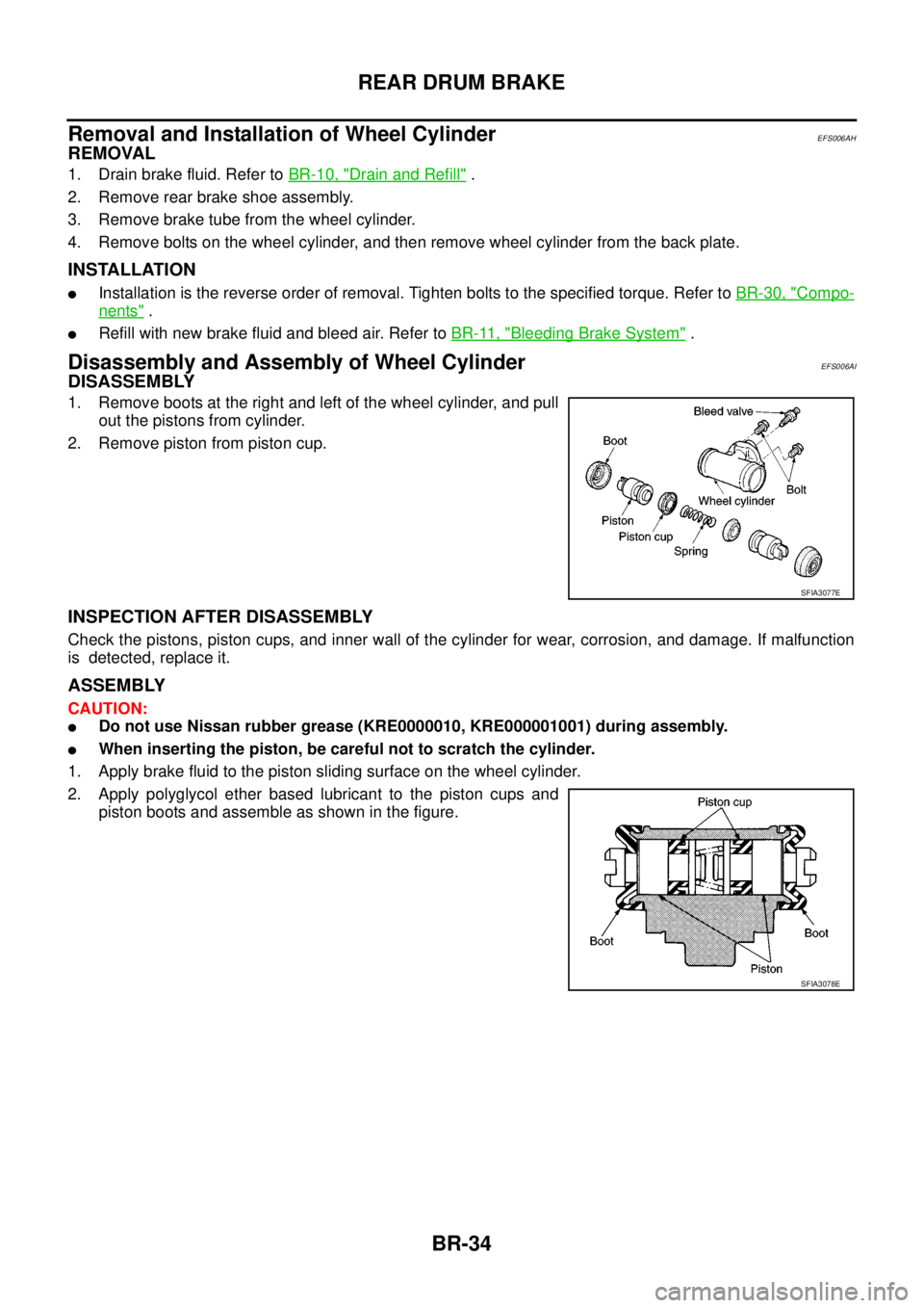
1. Remove boots at the right and left of the wheel cylinder, and pull
out the pistons from cylinder.
2. Remove piston from piston cup.
INSPECTION AFTER DISASSEMBLY
Check the pistons, piston cups, and inner wall of the cylinder for wear, corrosion, and damage. If malfunction
is detected, replace it.
ASSEMBLY
CAUTION:
lDo not use Nissan rubber grease (KRE0000010, KRE000001001) during assembly.
lWhen inserting the piston, be careful not to scratch the cylinder.
1. Apply brake fluid to the piston sliding surface on the wheel cylinder.
2. Apply polyglycol ether based lubricant to the piston cups and
piston boots and assemble as shown in the figure.
SFIA3077E
SFIA3078E
Page 869 of 3171
NOISE, VIBRATION AND HARSHNESS (NVH) TROUBLESHOOTING
CL-5
D
E
F
G
H
I
J
K
L
MA
B
CL
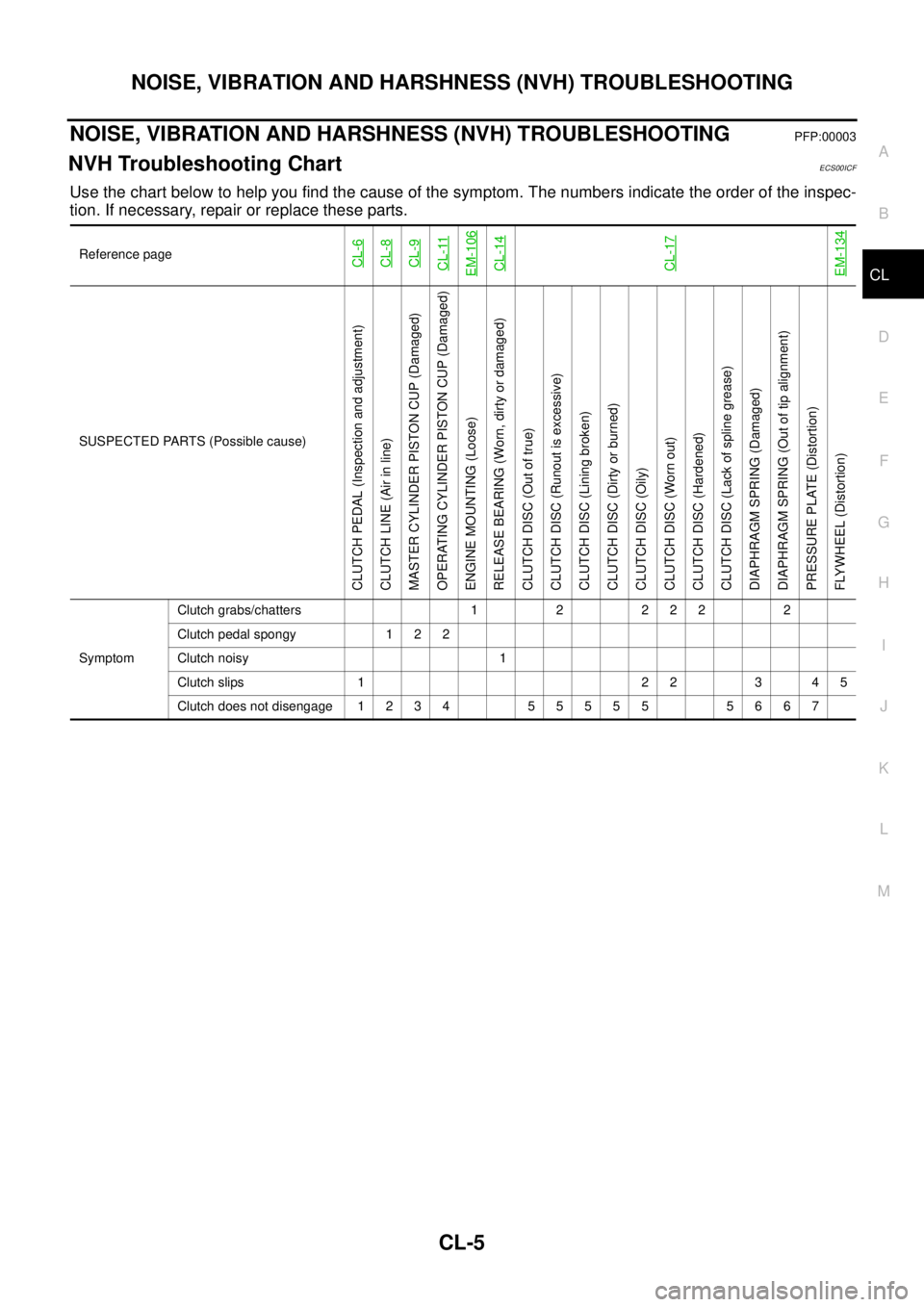
NOISE, VIBRATION AND HARSHNESS (NVH) TROUBLESHOOTINGPFP:00003
NVH Troubleshooting ChartECS00ICF
Use the chart below to help you find the cause of the symptom. The numbers indicate the order of the inspec-
tion. If necessary, repair or replace these parts.
Reference pageCL-6CL-8CL-9CL-11EM-106CL-14CL-17EM-134
SUSPECTED PARTS (Possible cause)
CLUTCH PEDAL (Inspection and adjustment)
CLUTCH LINE (Air in line)
MASTER CYLINDER PISTON CUP (Damaged)
OPERATING CYLINDER PISTON CUP (Damaged)
ENGINE MOUNTING (Loose)
RELEASE BEARING (Worn, dirty or damaged)
CLUTCH DISC (Out of true)
CLUTCH DISC (Runout is excessive)
CLUTCH DISC (Lining broken)
CLUTCH DISC (Dirty or burned)
CLUTCH DISC (Oily)
CLUTCH DISC (Worn out)
CLUTCH DISC (Hardened)
CLUTCH DISC (Lack of spline grease)
DIAPHRAGM SPRING (Damaged)
DIAPHRAGM SPRING (Out of tip alignment)
PRESSURE PLATE (Distortion)
FLYWHEEL (Distortion)
SymptomClutch grabs/chatters 1 2 2 2 2 2
Clutch pedal spongy 1 2 2
Clutch noisy 1
Clutch slips 1 2 2 3 4 5
Clutch does not disengage 1 2 3 4 5 5 5 5 5 5 6 6 7
Page 874 of 3171
CL-10
CLUTCH MASTER CYLINDER
6. Attach snap pin to clevis pin.
7. Install hose to nipple.
8. After completing this procedure, inspect and adjust for clutch pedal and then bleed the air from the clutch
hydraulic system. Refer toCL-6, "
On-Vehicle Inspection and Adjustment"andCL-8, "Air Bleeding Proce-
dure".
Disassembly and AssemblyECS00ICL
DISASSEMBLY
1. Remove spring pin using a pin punch.
2. Remove nipple and seal from cylinder body.
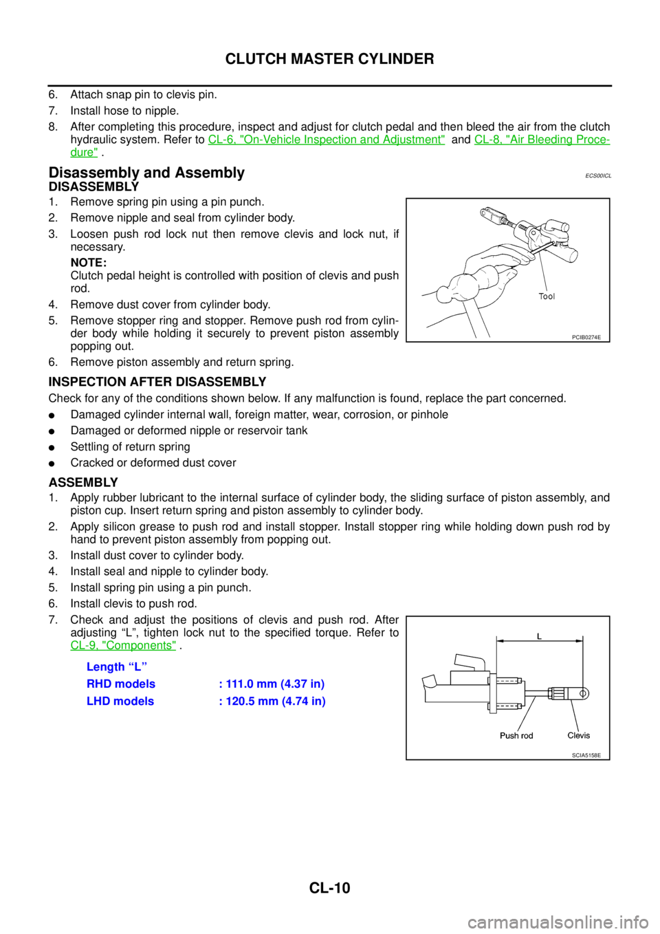
3. Loosen push rod lock nut then remove clevis and lock nut, if
necessary.
NOTE:
Clutch pedal height is controlled with position of clevis and push
rod.
4. Remove dust cover from cylinder body.
5. Remove stopper ring and stopper. Remove push rod from cylin-
der body while holding it securely to prevent piston assembly
popping out.
6. Remove piston assembly and return spring.
INSPECTION AFTER DISASSEMBLY
Check for any of the conditions shown below. If any malfunction is found, replace the part concerned.
lDamaged cylinder internal wall, foreign matter, wear, corrosion, or pinhole
lDamaged or deformed nipple or reservoir tank
lSettling of return spring
lCracked or deformed dust cover
ASSEMBLY
1. Apply rubber lubricant to the internal surface of cylinder body, the sliding surface of piston assembly, and
piston cup. Insert return spring and piston assembly to cylinder body.
2. Apply silicon grease to push rod and install stopper. Install stopper ring while holding down push rod by
hand to prevent piston assembly from popping out.
3. Install dust cover to cylinder body.
4. Install seal and nipple to cylinder body.
5. Install spring pin using a pin punch.
6. Install clevis to push rod.
7. Check and adjust the positions of clevis and push rod. After
adjusting “L”, tighten lock nut to the specified torque. Refer to
CL-9, "
Components".
PCIB0274E
Length “L”
RHD models : 111.0 mm (4.37 in)
LHD models : 120.5 mm (4.74 in)
SCIA5158E
Page 876 of 3171
CL-12
OPERATING CYLINDER
CAUTION:
Keep painted surface on the body or other parts free of clutch fluid. If it spills, wipe up immediately
and wash the affected area with water.
2. Remove clutch hose from operating cylinder assembly.
3. Remove operating cylinder assembly mounting bolts, and then remove operating cylinder assembly from
the vehicle.
INSTALLATION
Note the following, and install in the reverse order of removal.
lInstall clutch hose with care so that it will not be bent or twisted.
lTightenclutchhosetothespecifiedtorque.
CAUTION:
Do not reuse copper washer.
lAfter completing the procedure, bleed the air from the clutch hydraulic system. Refer toCL-8, "Air Bleed-
ing Procedure".
Disassembly and AssemblyECS00ICO
DISASSEMBLY
lRemove dust cover and push rod. Then remove piston, piston cup and piston spring from cylinder body.
INSPECTION AFTER DISASSEMBLY
Check for any of the conditions shown below. If any malfunction is found, replace the part concerned.
lDamage to cylinder internal surface or piston sliding surface. Foreign matter, wear, corrosion, or pinhole
lSettling of piston spring
lCracked or deformed dust cover
ASSEMBLY
1. Apply rubber lubricant to cylinder body internal surface and rubber grease to piston cup and piston. Insert
piston assembly and piston spring into cylinder body.
2. Apply rubber grease to dust cover and then install push rod and dust cover.
Page 879 of 3171
CLUTCH RELEASE MECHANISM
CL-15
D
E
F
G
H
I
J
K
L
MA
B
CL
INSPECTION AFTER REMOVAL
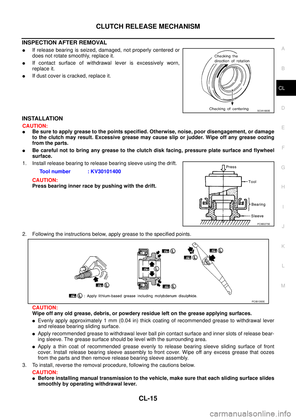
lIf release bearing is seized, damaged, not properly centered or
does not rotate smoothly, replace it.
lIf contact surface of withdrawal lever is excessively worn,
replace it.
lIf dust cover is cracked, replace it.
INSTALLATION
CAUTION:
lBe sure to apply grease to the points specified. Otherwise, noise, poor disengagement, or damage
to the clutch may result. Excessive grease may cause slip or judder. Wipe off any grease oozing
from the parts.
lBe careful not to bring any grease to the clutch disk facing, pressure plate surface and flywheel
surface.
1. Install release bearing to release bearing sleeve using the drift.
CAUTION:
Press bearing inner race by pushing with the drift.
2. Following the instructions below, apply grease to the specified points.
CAUTION:
Wipe off any old grease, debris, or powdery residue left on the grease applying surfaces.
lEvenly apply approximately 1 mm (0.04 in) thick coating of recommended grease to withdrawal lever
and release bearing sliding surface.
lApply recommended grease to withdrawal lever ball pin contact surface and inner slots of release bear-
ing sleeve. The grease surface should be level with the surrounding area.
lApply a thin coat of recommended grease evenly to release bearing sleeve sliding surface of front
cover. Install release bearing sleeve assembly to front cover. Wipe off any excess grease that oozes
from the parts and then remove release bearing sleeve assembly.
3. To install, reverse the removal procedure, following the cautions below.
CAUTION:
lBefore installing manual transmission to the vehicle, make sure that each sliding surface slides
smoothly by operating withdrawal lever.
SCIA1660E
Tool number : KV30101400
PCIB0275E
PCIB1393E
Page 881 of 3171
CLUTCH DISC, CLUTCH COVER AND FLYWHEEL
CL-17
D
E
F
G
H
I
J
K
L
MA
B
CL
CLUTCH DISC, CLUTCH COVER AND FLYWHEELPFP:30100
Removal and InstallationECS00ICR
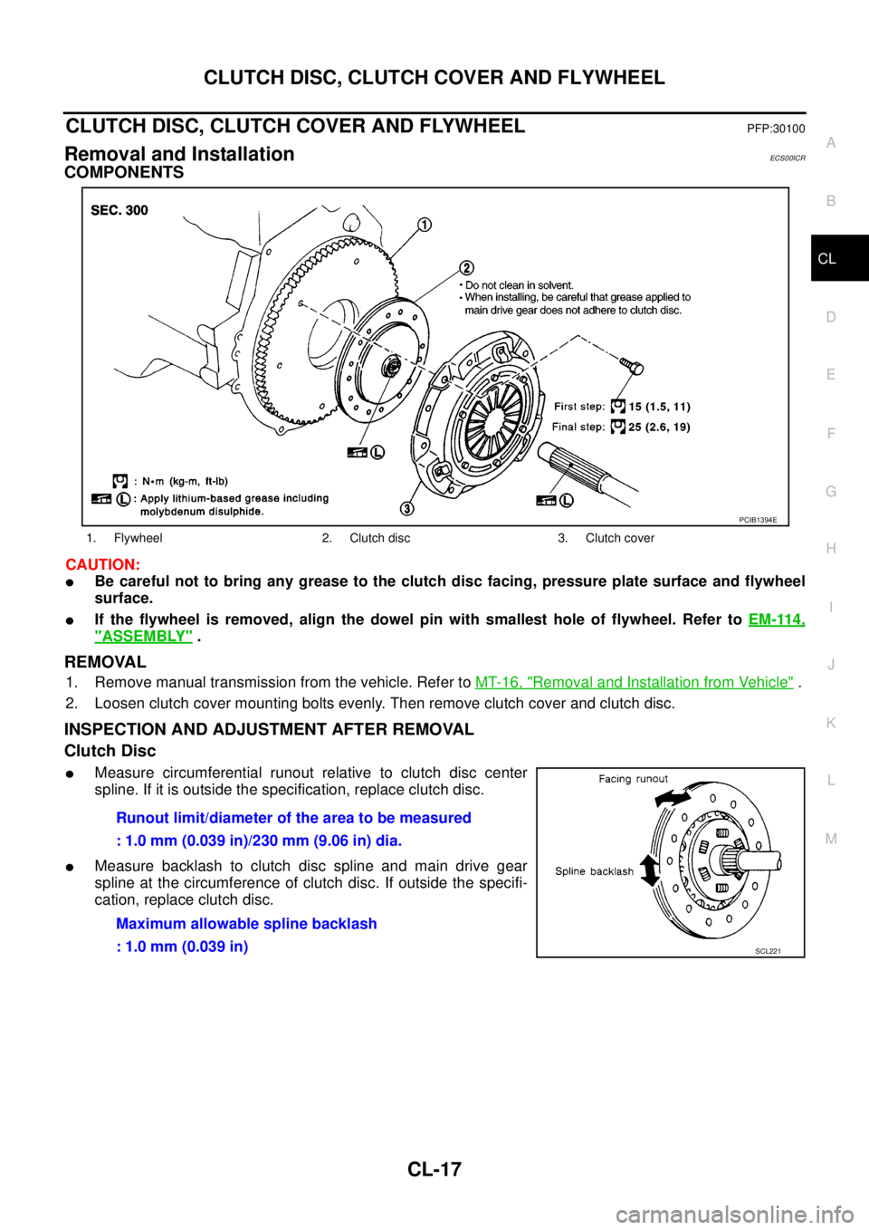
COMPONENTS
CAUTION:
lBe careful not to bring any grease to the clutch disc facing, pressure plate surface and flywheel
surface.
lIf the flywheel is removed, align the dowel pin with smallest hole of flywheel. Refer toEM-114,
"ASSEMBLY".
REMOVAL
1. Remove manual transmission from the vehicle. Refer toMT-16, "Removal and Installation from Vehicle".
2. Loosen clutch cover mounting bolts evenly. Then remove clutch cover and clutch disc.
INSPECTION AND ADJUSTMENT AFTER REMOVAL
Clutch Disc
lMeasure circumferential runout relative to clutch disc center
spline. If it is outside the specification, replace clutch disc.
lMeasure backlash to clutch disc spline and main drive gear
spline at the circumference of clutch disc. If outside the specifi-
cation, replace clutch disc.
1. Flywheel 2. Clutch disc 3. Clutch cover
PCIB1394E
Runout limit/diameter of the area to be measured
: 1.0 mm (0.039 in)/230 mm (9.06 in) dia.
Maximum allowable spline backlash
: 1.0 mm (0.039 in)
SCL221
Page 882 of 3171
CL-18
CLUTCH DISC, CLUTCH COVER AND FLYWHEEL
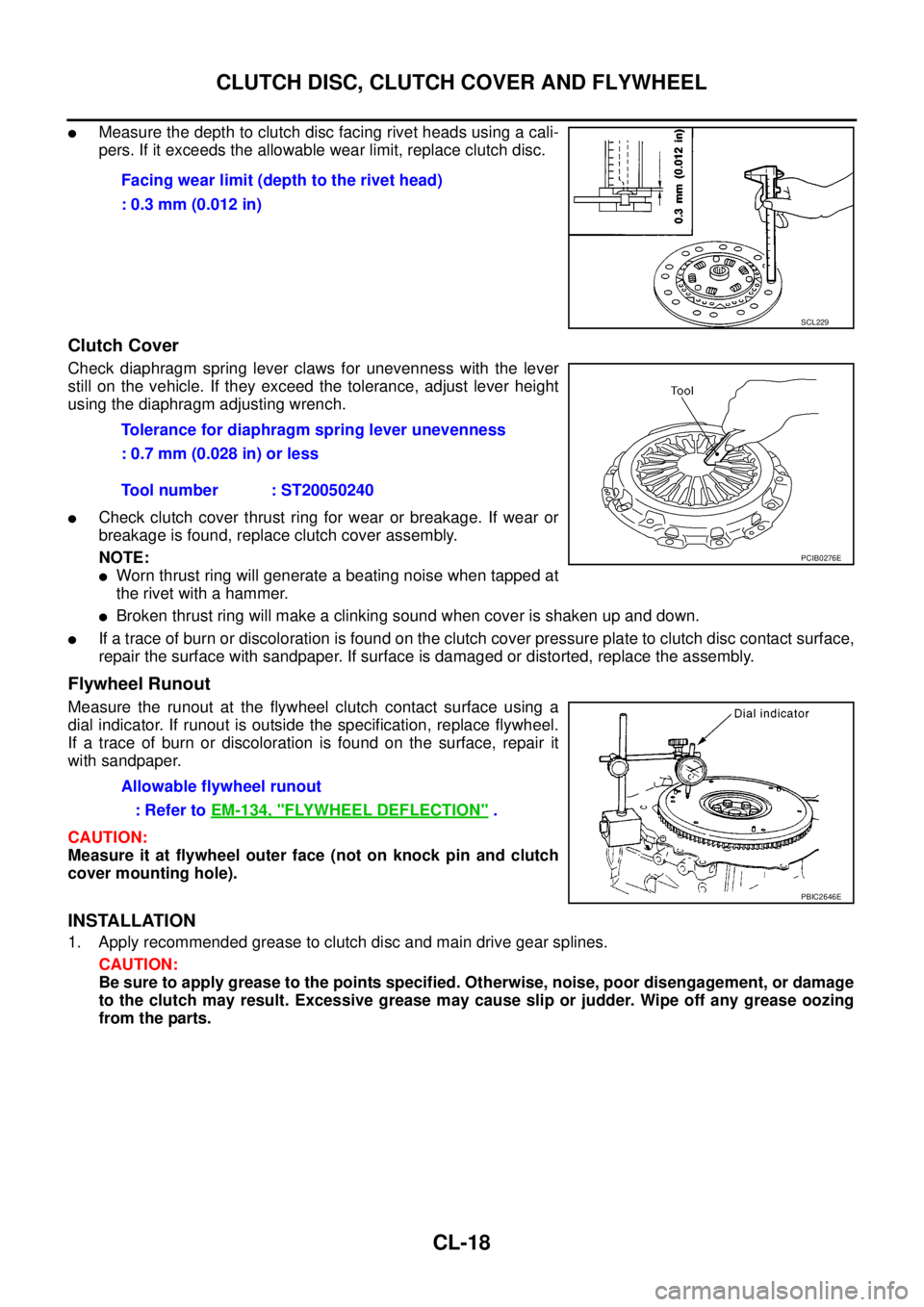
lMeasure the depth to clutch disc facing rivet heads using a cali-
pers. If it exceeds the allowable wear limit, replace clutch disc.
Clutch Cover
Check diaphragm spring lever claws for unevenness with the lever
still on the vehicle. If they exceed the tolerance, adjust lever height
using the diaphragm adjusting wrench.
lCheck clutch cover thrust ring for wear or breakage. If wear or
breakage is found, replace clutch cover assembly.
NOTE:
lWorn thrust ring will generate a beating noise when tapped at
therivetwithahammer.
lBroken thrust ring will make a clinking sound when cover is shaken up and down.
lIf a trace of burn or discoloration is found on the clutch cover pressure plate to clutch disc contact surface,
repair the surface with sandpaper. If surface is damaged or distorted, replace the assembly.
Flywheel Runout
Measure the runout at the flywheel clutch contact surface using a
dial indicator. If runout is outside the specification, replace flywheel.
If a trace of burn or discoloration is found on the surface, repair it
with sandpaper.
CAUTION:
Measure it at flywheel outer face (not on knock pin and clutch
cover mounting hole).
INSTALLATION
1. Apply recommended grease to clutch disc and main drive gear splines.
CAUTION:
Be sure to apply grease to the points specified. Otherwise, noise, poor disengagement, or damage
to the clutch may result. Excessive grease may cause slip or judder. Wipe off any grease oozing
from the parts.Facing wear limit (depth to the rivet head)
: 0.3 mm (0.012 in)
SCL229
Tolerance for diaphragm spring lever unevenness
: 0.7 mm (0.028 in) or less
Tool number : ST20050240
PCIB0276E
Allowable flywheel runout
:RefertoEM-134, "
FLYWHEEL DEFLECTION".
PBIC2646E