grease NISSAN NAVARA 2005 Repair Workshop Manual
[x] Cancel search | Manufacturer: NISSAN, Model Year: 2005, Model line: NAVARA, Model: NISSAN NAVARA 2005Pages: 3171, PDF Size: 49.59 MB
Page 15 of 3171
PRECAUTIONS
AT-7
D
E
F
G
H
I
J
K
L
MA
B
AT
PRECAUTIONSPFP:00001
Precautions for Supplemental Restraint System (SRS) “AIR BAG” and “SEAT
BELT PRE-TENSIONER”
ECS00IPT
The Supplemental Restraint System such as “AIR BAG” and “SEAT BELT PRE-TENSIONER”, used along
with a front seat belt, helps to reduce the risk or severity of injury to the driver and front passenger for certain
types of collision. Information necessary to service the system safely is included in the SRS and SB section of
this Service Manual.
WARNING:
lTo avoid rendering the SRS inoperative, which could increase the risk of personal injury or death
in the event of a collision which would result in air bag inflation, all maintenance must be per-
formed by an authorized NISSAN/INFINITI dealer.
lImproper maintenance, including incorrect removal and installation of the SRS, can lead to per-
sonal injury caused by unintentional activation of the system. For removal of Spiral Cable and Air
Bag Module, see the SRS section.
lDo not use electrical test equipment on any circuit related to the SRS unless instructed to in this
Service Manual. SRS wiring harnesses can be identified by yellow and/or orange harnesses or
harness connectors.
PrecautionsECS00IPR
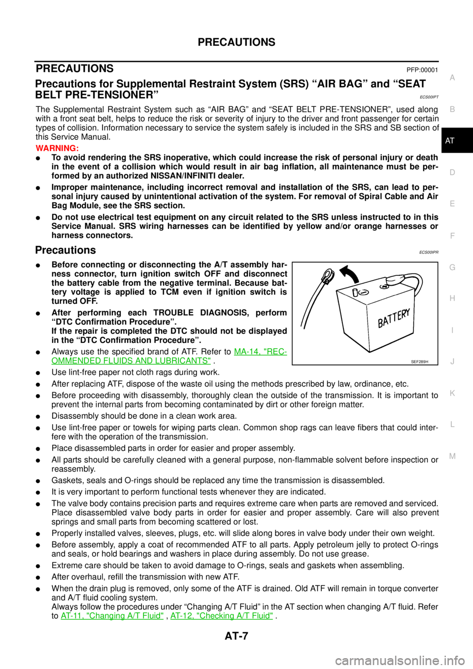
lBefore connecting or disconnecting the A/T assembly har-
ness connector, turn ignition switch OFF and disconnect
the battery cable from the negative terminal. Because bat-
tery voltage is applied to TCM even if ignition switch is
turned OFF.
lAfter performing each TROUBLE DIAGNOSIS, perform
“DTC Confirmation Procedure”.
If the repair is completed the DTC should not be displayed
in the “DTC Confirmation Procedure”.
lAlways use the specified brand of ATF. Refer toMA-14, "REC-
OMMENDED FLUIDS AND LUBRICANTS".
lUse lint-free paper not cloth rags during work.
lAfter replacing ATF, dispose of the waste oil using the methods prescribed by law, ordinance, etc.
lBefore proceeding with disassembly, thoroughly clean the outside of the transmission. It is important to
prevent the internal parts from becoming contaminated by dirt or other foreign matter.
lDisassembly should be done in a clean work area.
lUse lint-free paper or towels for wiping parts clean. Common shop rags can leave fibers that could inter-
fere with the operation of the transmission.
lPlace disassembled parts in order for easier and proper assembly.
lAll parts should be carefully cleaned with a general purpose, non-flammable solvent before inspection or
reassembly.
lGaskets, seals and O-rings should be replaced any time the transmission is disassembled.
lIt is very important to perform functional tests whenever they are indicated.
lThe valve body contains precision parts and requires extreme care when parts are removed and serviced.
Place disassembled valve body parts in order for easier and proper assembly. Care will also prevent
springs and small parts from becoming scattered or lost.
lProperly installed valves, sleeves, plugs, etc. will slide along bores in valve body under their own weight.
lBefore assembly, apply a coat of recommended ATF to all parts. Apply petroleum jelly to protect O-rings
and seals, or hold bearings and washers in place during assembly. Do not use grease.
lExtreme care should be taken to avoid damage to O-rings, seals and gaskets when assembling.
lAfter overhaul, refill the transmission with new ATF.
lWhen the drain plug is removed, only some of the ATF is drained. Old ATF will remain in torque converter
and A/T fluid cooling system.
Always follow the procedures under “Changing A/T Fluid” in the AT section when changing A/T fluid. Refer
toAT-11, "
Changing A/T Fluid",AT-12, "Checking A/T Fluid".
SEF289H
Page 588 of 3171
BL-4
PRECAUTIONS
PRECAUTIONS
PFP:00001
Precautions for Supplemental Restraint System (SRS) “AIR BAG” and “SEAT
BELT PRE-TENSIONER”
EIS00DHW
The Supplemental Restraint System such as “AIR BAG” and “SEAT BELT PRE-TENSIONER”, used along
with a front seat belt, helps to reduce the risk or severity of injury to the driver and front passenger for certain
types of collision. Information necessary to service the system safely is included in the SRS and SB section of
this Service Manual.
WARNING:
lTo avoid rendering the SRS inoperative, which could increase the risk of personal injury or death
in the event of a collision which would result in air bag inflation, all maintenance must be per-
formed by an authorized NISSAN/INFINITI dealer.
lImproper maintenance, including incorrect removal and installation of the SRS, can lead to per-
sonal injury caused by unintentional activation of the system. For removal of Spiral Cable and Air
Bag Module, see the SRS section.
lDo not use electrical test equipment on any circuit related to the SRS unless instructed to in this
Service Manual. SRS wiring harnesses can be identified by yellow and/or orange harnesses or
harness connectors.
Precautions for procedures with out cowl top coverEIS00DHY
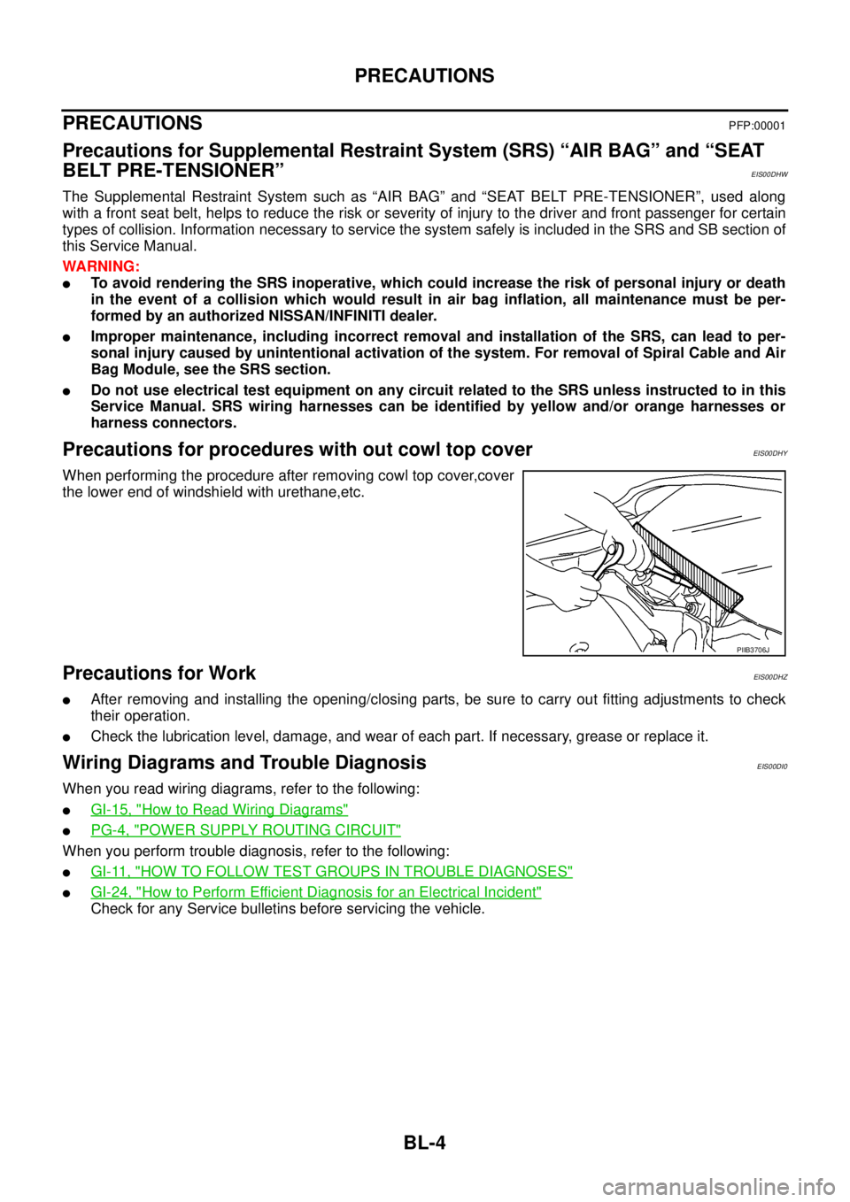
When performing the procedure after removing cowl top cover,cover
the lower end of windshield with urethane,etc.
Precautions for WorkEIS00DHZ
lAfter removing and installing the opening/closing parts, be sure to carry out fitting adjustments to check
their operation.
lCheck the lubrication level, damage, and wear of each part. If necessary, grease or replace it.
Wiring Diagrams and Trouble DiagnosisEIS00DI0
When you read wiring diagrams, refer to the following:
lGI-15, "How to Read Wiring Diagrams"
lPG-4, "POWER SUPPLY ROUTING CIRCUIT"
When you perform trouble diagnosis, refer to the following:
lGI-11, "HOW TO FOLLOW TEST GROUPS IN TROUBLE DIAGNOSES"
lGI-24, "How to Perform Efficient Diagnosis for an Electrical Incident"
Check for any Service bulletins before servicing the vehicle.
PIIB3706J
Page 592 of 3171
BL-8
SQUEAK AND RATTLE TROUBLE DIAGNOSES
FELT CLOTHTAPE
Used to insulate where movement does not occur. Ideal for instrument panel applications.
68370-4B000: 15´25 mm (0.59´0.98 in) pad/68239-13E00: 5 mm (0.20 in) wide tape roll
The following materials, not available through NISSAN Parts Department, can also be used to repair squeaks
and rattles.
UHMW(TEFLON) TAPE
Insulates where slight movement is present. Ideal for instrument panel applications.
SILICONE GREASE
Used in place of UHMW tape that will be visible or not fit.
Note: Will only last a few months.
SILICONE SPRAY
Use when grease cannot be applied.
DUCT TAPE
Use to eliminate movement.
CONFIRM THE REPAIR
Confirm that the cause of a noise is repaired by test driving the vehicle. Operate the vehicle under the same
conditions as when the noise originally occurred. Refer to the notes on the Diagnostic Worksheet.
Generic Squeak and Rattle TroubleshootingEIS00DI3
Refer to Table of Contents for specific component removal and installation information.
INSTRUMENT PANEL
Most incidents are caused by contact and movement between:
1. Cluster lid A and instrument panel
2. Acrylic lens and combination meter housing
3. Instrument panel to front pillar garnish
4. Instrument panel to windshield
5. Instrument panel mounting pins
6. Wiring harnesses behind the combination meter
7. A/C defroster duct and duct joint
These incidents can usually be located by tapping or moving the components to duplicate the noise or by
pressing on the components while driving to stop the noise. Most of these incidents can be repaired by apply-
ing felt cloth tape or silicon spray (in hard to reach areas). Urethane pads can be used to insulate wiring har-
ness.
CAUTION:
Do not use silicone spray to isolate a squeak or rattle. If you saturate the area with silicone, you will
not be able to recheck the repair.
CENTER CONSOLE
Components to pay attention to include:
1. Shifter assembly cover to finisher
2. A/C control unit and cluster lid C
3. Wiring harnesses behind audio and A/C control unit
The instrument panel repair and isolation procedures also apply to the center console.
DOORS
Pay attention to the:
1. Finisher and inner panel making a slapping noise
2. Inside handle escutcheon to door finisher
3. Wiring harnesses tapping
4. Door striker out of alignment causing a popping noise on starts and stops
Tapping or moving the components or pressing on them while driving to duplicate the conditions can isolate
many of these incidents. You can usually insulate the areas with felt cloth tape or insulator foam blocks to
repair the noise.
Page 601 of 3171
HOOD
BL-17
C
D
E
F
G
H
J
K
L
MA
B
BL
Hood Lock Control InspectionEIS00BQ1
CAUTION:
If the hood lock cable is bent or deformed, replace it.
1. Make sure that the hood lock secondary latch is properly engaged with the secondary striker with hood's
own weight.
2. Make sure that the hood lock primary latch is securely engaged with the hood striker with hood's own
weight by dropping it from approx. 200 mm (7.87 in) height.
CAUTION:
Do not drop hood from a height of 300 mm (11.81 in) or more.
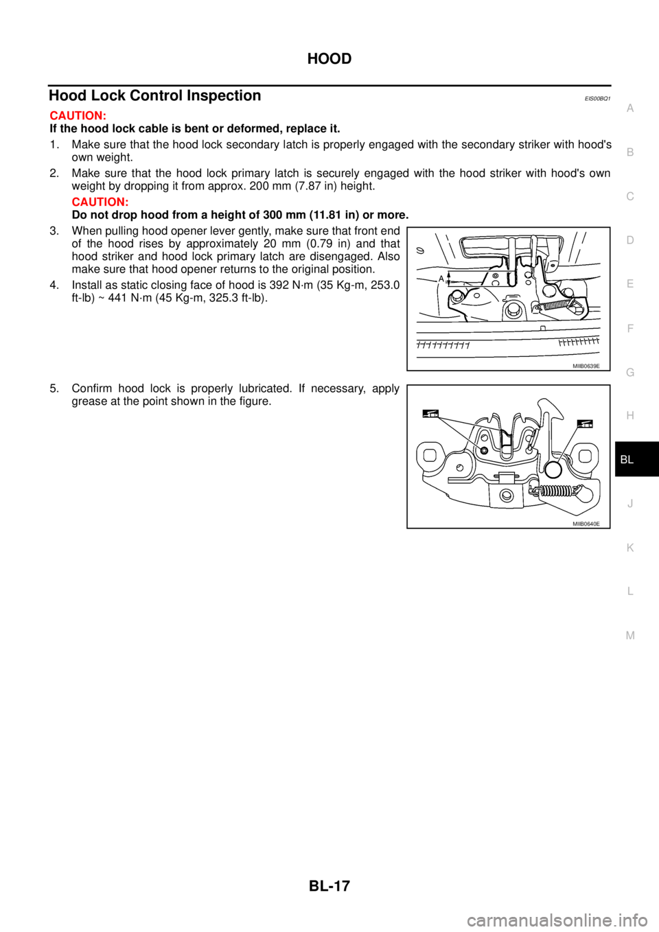
3. When pulling hood opener lever gently, make sure that front end
of the hood rises by approximately 20 mm (0.79 in) and that
hood striker and hood lock primary latch are disengaged. Also
make sure that hood opener returns to the original position.
4. Install as static closing face of hood is 392 N·m (35 Kg-m, 253.0
ft-lb) ~ 441 N·m (45 Kg-m, 325.3 ft-lb).
5. Confirm hood lock is properly lubricated. If necessary, apply
grease at the point shown in the figure.
MIIB0639E
MIIB0640E
Page 700 of 3171
BL-116
MULTI-REMOTE CONTROL SYSTEM
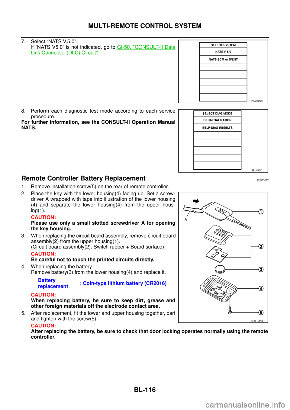
7. Select “NATS V.5.0”.
If “NATS V5.0” is not indicated, go toGI-50, "
CONSULT-II Data
Link Connector (DLC) Circuit".
8. Perform each diagnostic test mode according to each service
procedure.
For further information, see the CONSULT-II Operation Manual
NATS.
Remote Controller Battery ReplacementEIS00DBV
1. Remove installation screw(5) on the rear of remote controller.
2. Place the key with the lower housing(4) facing up. Set a screw-
driver A wrapped with tape into illustration of the lower housing
(4) and separate the lower housing(4) from the upper hous-
ing(1).
CAUTION:
Please use only a small slotted screwdriver A for opening
the key housing.
3. When replacing the circuit board assembly, remove circuit board
assembly(2) from the upper housing(1).
(Circuit board assembly(2): Switch rubber + Board surface)
CAUTION:
Be careful not to touch the printed circuits directly.
4. When replacing the battery.
Remove battery(3) from the lower housing(4) and replace it.
CAUTION:
When replacing battery, be sure to keep dirt, grease and
other foreign materials off the electrode contact area.
5. After replacement, fit the lower and upper housing together, part
and tighten with the screw(5).
CAUTION:
After replacing the battery, be sure to check that door locking operates normally using the remote
controller.
PIIA9327E
SEL150X
Battery
replacement: Coin-type lithium battery (CR2016)
MIIB1066E
Page 704 of 3171
BL-120
DOOR
FRONT DOOR
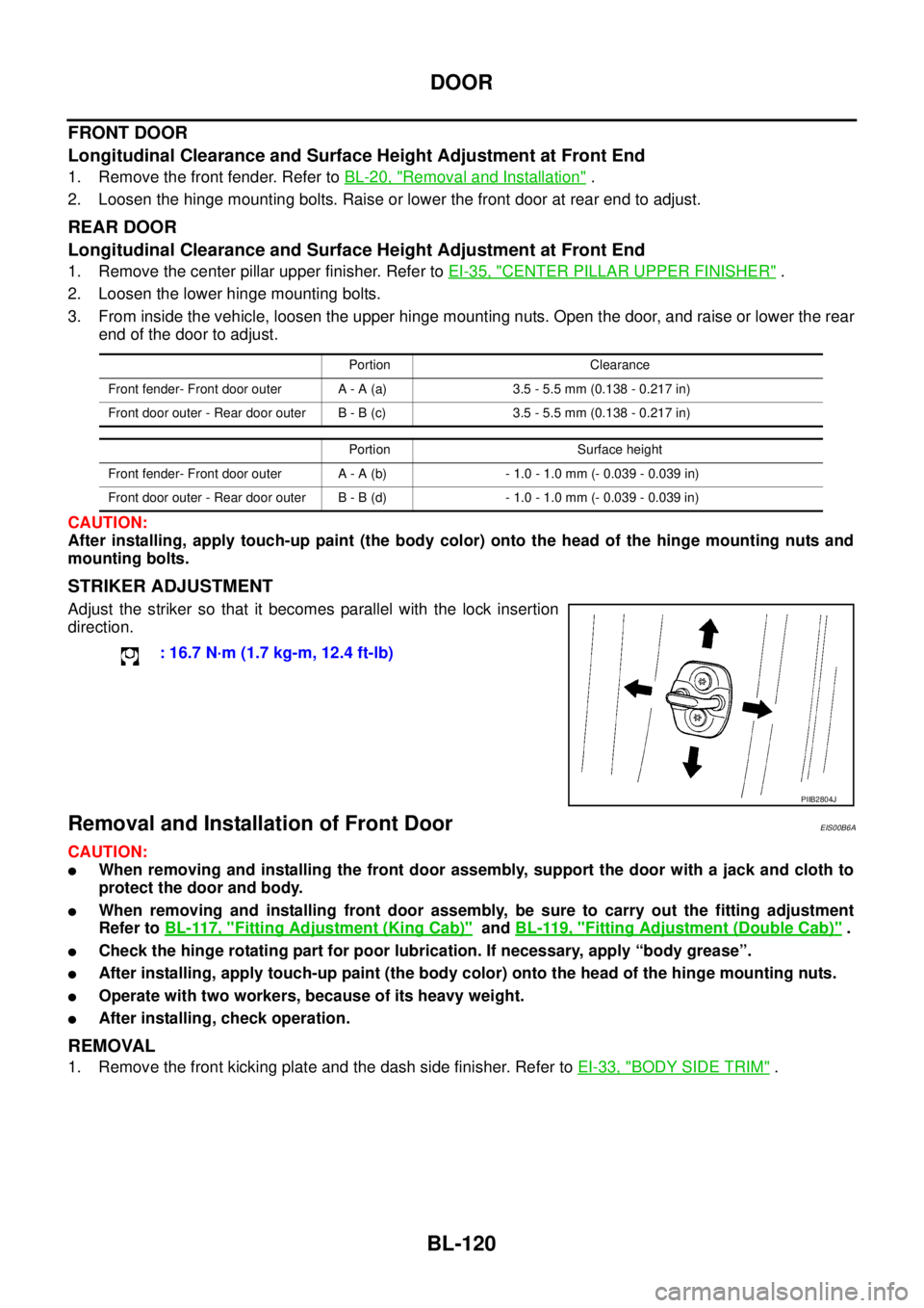
Longitudinal Clearance and Surface Height Adjustment at Front End
1. Remove the front fender. Refer toBL-20, "Removal and Installation".
2. Loosen the hinge mounting bolts. Raise or lower the front door at rear end to adjust.
REAR DOOR
Longitudinal Clearance and Surface Height Adjustment at Front End
1. Remove the center pillar upper finisher. Refer toEI-35, "CENTER PILLAR UPPER FINISHER".
2. Loosen the lower hinge mounting bolts.
3. From inside the vehicle, loosen the upper hinge mounting nuts. Open the door, and raise or lower the rear
end of the door to adjust.
CAUTION:
After installing, apply touch-up paint (the body color) onto the head of the hinge mounting nuts and
mounting bolts.
STRIKER ADJUSTMENT
Adjust the striker so that it becomes parallel with the lock insertion
direction.
Removal and Installation of Front DoorEIS00B6A
CAUTION:
lWhen removing and installing the front door assembly, support the door with a jack and cloth to
protect the door and body.
lWhen removing and installing front door assembly, be sure to carry out the fitting adjustment
Refer toBL-117, "
Fitting Adjustment (King Cab)"andBL-119, "Fitting Adjustment (Double Cab)".
lCheck the hinge rotating part for poor lubrication. If necessary, apply “body grease”.
lAfter installing, apply touch-up paint (the body color) onto the head of the hinge mounting nuts.
lOperate with two workers, because of its heavy weight.
lAfter installing, check operation.
REMOVAL
1. Remove the front kicking plate and the dash side finisher. Refer toEI-33, "BODY SIDE TRIM".
Portion Clearance
Front fender- Front door outer A - A (a) 3.5 - 5.5 mm (0.138 - 0.217 in)
Front door outer - Rear door outer B - B (c) 3.5 - 5.5 mm (0.138 - 0.217 in)
Portion Surface height
Front fender- Front door outer A - A (b) - 1.0 - 1.0 mm (- 0.039 - 0.039 in)
Front door outer - Rear door outer B - B (d) - 1.0 - 1.0 mm (- 0.039 - 0.039 in)
: 16.7 N·m (1.7 kg-m, 12.4 ft-lb)
PIIB2804J
Page 705 of 3171
DOOR
BL-121
C
D
E
F
G
H
J
K
L
MA
B
BL
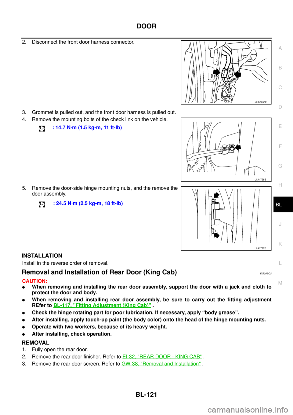
2. Disconnect the front door harness connector.
3. Grommet is pulled out, and the front door harness is pulled out.
4. Remove the mounting bolts of the check link on the vehicle.
5. Remove the door-side hinge mounting nuts, and the remove the
door assembly.
INSTALLATION
Install in the reverse order of removal.
Removal and Installation of Rear Door (King Cab)EIS00BQ2
CAUTION:
lWhen removing and installing the rear door assembly, support the door with a jack and cloth to
protect the door and body.
lWhen removing and installing rear door assembly, be sure to carry out the fitting adjustment
REfer toBL-117, "
Fitting Adjustment (King Cab)".
lCheck the hinge rotating part for poor lubrication. If necessary, apply “body grease”.
lAfter installing, apply touch-up paint (the body color) onto the head of the hinge mounting nuts.
lOperate with two workers, because of its heavy weight.
lAfter installing, check operation.
REMOVAL
1. Fully open the rear door.
2. Remove the rear door finisher. Refer toEI-32, "
REAR DOOR - KING CAB".
3. Remove the rear door screen. Refer toGW-38, "
Removal and Installation".
MIIB0655E
: 14.7 N·m (1.5 kg-m, 11 ft-lb)
LIIA1726E
: 24.5 N·m (2.5 kg-m, 18 ft-lb)
LIIA1727E
Page 707 of 3171
DOOR
BL-123
C
D
E
F
G
H
J
K
L
MA
B
BL
Removal and Installation of Rear Door (Double Cab)EIS00DUN
CAUTION:
lWhen removing and installing the rear door assembly, support the door with a jack and cloth to
protect the door and body.
lWhen removing and installing rear door assembly, be sure to carry out the fitting adjustment
REfer toBL-119, "
Fitting Adjustment (Double Cab)".
lCheck the hinge rotating part for poor lubrication. If necessary, apply “body grease”.
lAfter installing, apply touch-up paint (the body color) onto the head of the hinge mounting nuts.
lOperate with two workers, because of its heavy weight.
lAfter installing, check operation.
REMOVAL
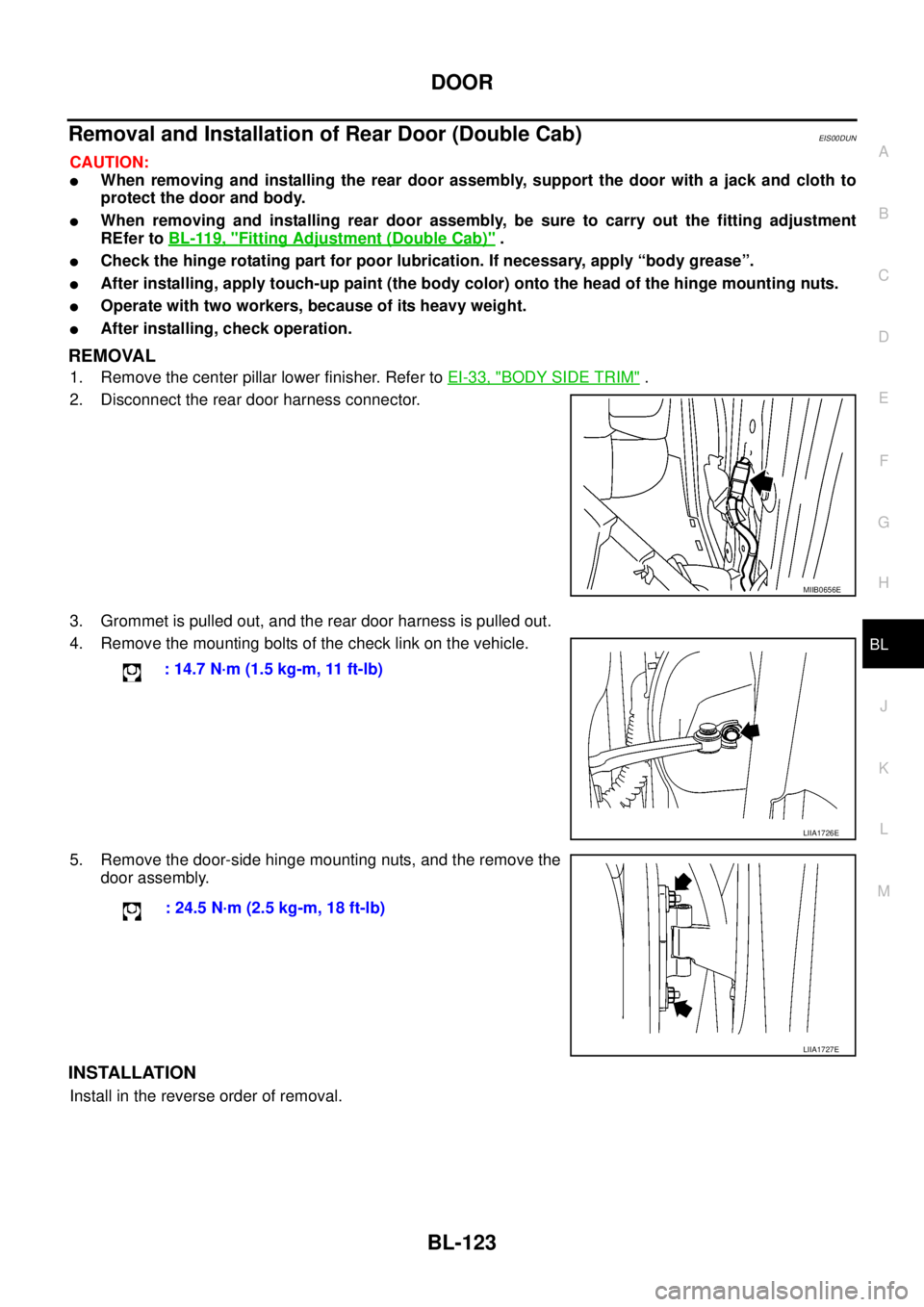
1. Remove the center pillar lower finisher. Refer toEI-33, "BODY SIDE TRIM".
2. Disconnect the rear door harness connector.
3. Grommet is pulled out, and the rear door harness is pulled out.
4. Remove the mounting bolts of the check link on the vehicle.
5. Remove the door-side hinge mounting nuts, and the remove the
door assembly.
INSTALLATION
Install in the reverse order of removal.
MIIB0656E
: 14.7 N·m (1.5 kg-m, 11 ft-lb)
LIIA1726E
: 24.5 N·m (2.5 kg-m, 18 ft-lb)
LIIA1727E
Page 794 of 3171
BR-8
BRAKE PEDAL
Removal and Installation
EFS005SH
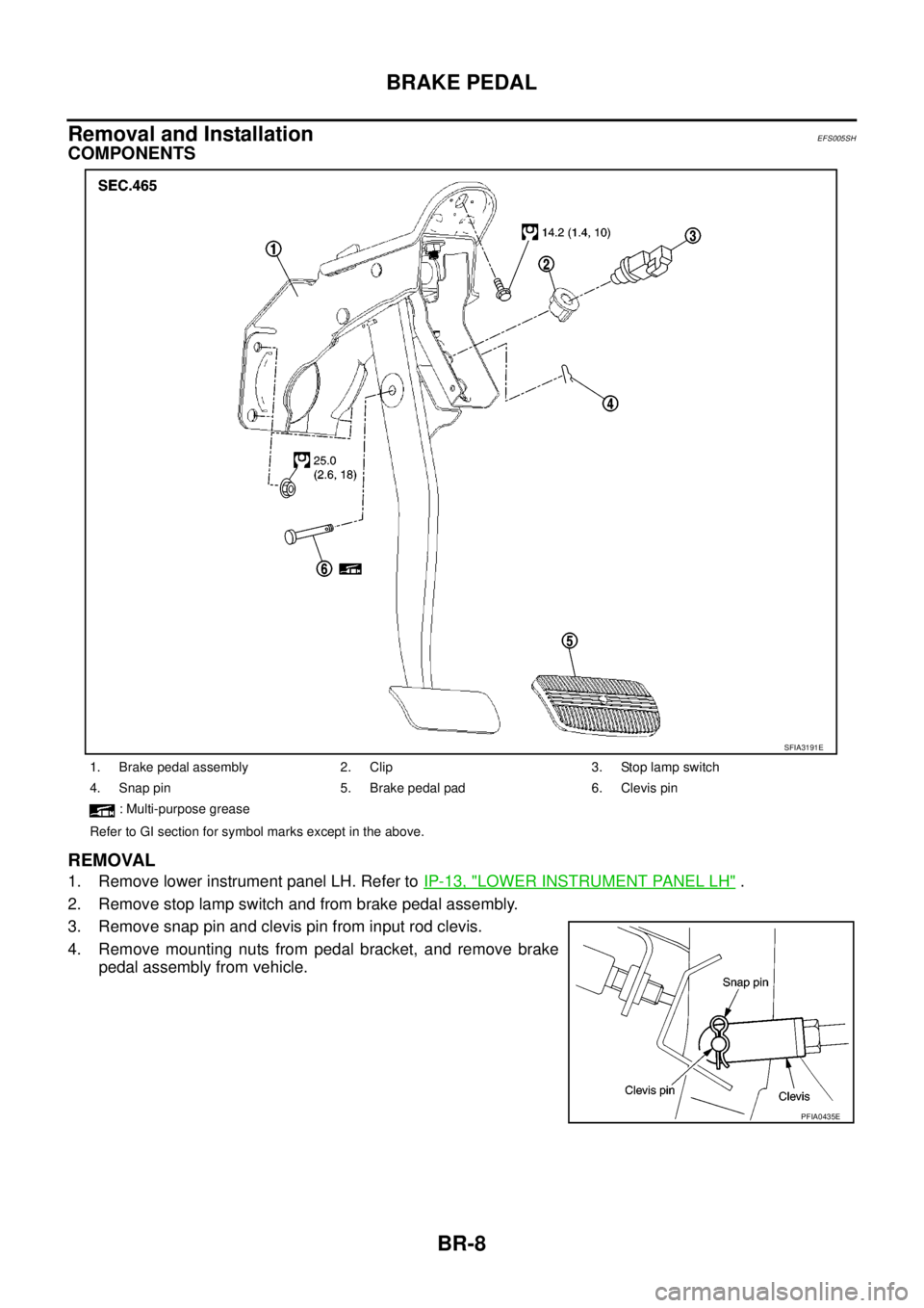
COMPONENTS
REMOVAL
1. Remove lower instrument panel LH. Refer toIP-13, "LOWER INSTRUMENT PANEL LH".
2. Remove stop lamp switch and from brake pedal assembly.
3. Remove snap pin and clevis pin from input rod clevis.
4. Remove mounting nuts from pedal bracket, and remove brake
pedal assembly from vehicle.
1. Brake pedal assembly 2. Clip 3. Stop lamp switch
4. Snap pin 5. Brake pedal pad 6. Clevis pin
: Multi-purpose grease
Refer to GI section for symbol marks except in the above.
SFIA3191E
PFIA0435E
Page 810 of 3171
BR-24
FRONT DISC BRAKE
FRONT DISC BRAKE
PFP:41000
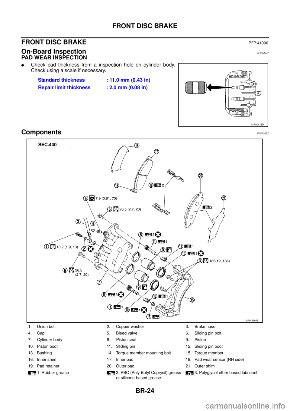
On-Board InspectionEFS005SY
PAD WEAR INSPECTION
lCheck pad thickness from a inspection hole on cylinder body.
Check using a scale if necessary.
ComponentsEFS005SZ
Standard thickness : 11.0 mm (0.43 in)
Repair limit thickness : 2.0 mm (0.08 in)
MAA0439D
1. Union bolt 2. Copper washer 3. Brake hose
4. Cap 5. Bleed valve 6. Sliding pin bolt
7. Cylinder body 8. Piston seal 9. Piston
10. Piston boot 11. Sliding pin 12. Sliding pin boot
13. Bushing 14. Torque member mounting bolt 15. Torque member
16. Inner shim 17. Inner pad 18. Pad wear sensor (RH side)
19. Pad retainer 20. Outer pad 21. Outer shim
1: Rubber grease 2: PBC (Poly Butyl Cuprysil) grease
or silicone-based grease3: Polyglycol ether based lubricant
SFIA3168E