NISSAN NAVARA 2005 Repair Workshop Manual
Manufacturer: NISSAN, Model Year: 2005, Model line: NAVARA, Model: NISSAN NAVARA 2005Pages: 3171, PDF Size: 49.59 MB
Page 2381 of 3171
MT-64
TRANSMISSION ASSEMBLY
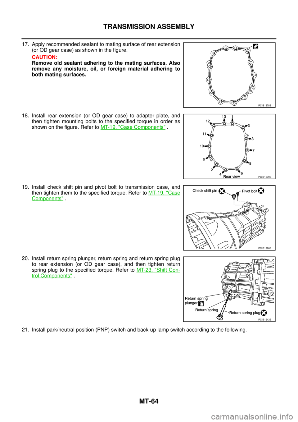
17. Apply recommended sealant to mating surface of rear extension
(or OD gear case) as shown in the figure.
CAUTION:
Remove old sealant adhering to the mating surfaces. Also
remove any moisture, oil, or foreign material adhering to
both mating surfaces.
18. Install rear extension (or OD gear case) to adapter plate, and
then tighten mounting bolts to the specified torque in order as
shown on the figure. Refer toMT-19, "
Case Components".
19. Install check shift pin and pivot bolt to transmission case, and
then tighten them to the specified torque. Refer toMT-19, "
Case
Components".
20. Install return spring plunger, return spring and return spring plug
to rear extension (or OD gear case), and then tighten return
spring plug to the specified torque. Refer toMT-23, "
Shift Con-
trol Components".
21. Install park/neutral position (PNP) switch and back-up lamp switch according to the following.
PCIB1278E
PCIB1279E
PCIB1226E
PCIB1643E
Page 2382 of 3171
TRANSMISSION ASSEMBLY
MT-65
D
E
F
G
H
I
J
K
L
MA
B
MT
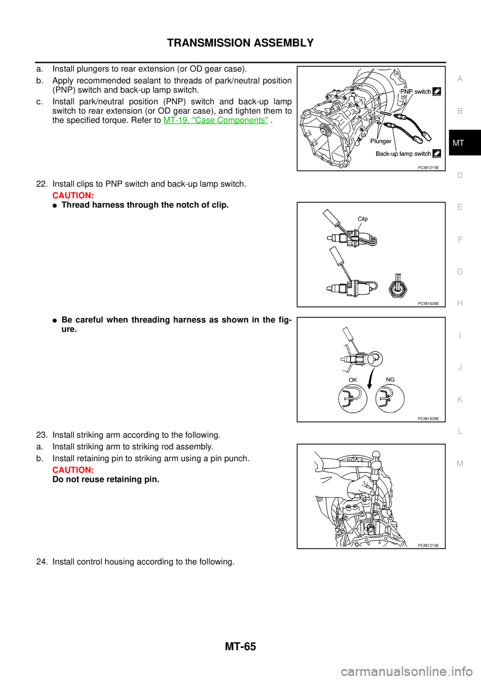
a. Install plungers to rear extension (or OD gear case).
b. Apply recommended sealant to threads of park/neutral position
(PNP) switch and back-up lamp switch.
c. Install park/neutral position (PNP) switch and back-up lamp
switch to rear extension (or OD gear case), and tighten them to
the specified torque. Refer toMT-19, "
Case Components".
22. Install clips to PNP switch and back-up lamp switch.
CAUTION:
lThread harness through the notch of clip.
lBe careful when threading harness as shown in the fig-
ure.
23. Install striking arm according to the following.
a. Install striking arm to striking rod assembly.
b. Install retaining pin to striking arm using a pin punch.
CAUTION:
Do not reuse retaining pin.
24. Install control housing according to the following.
PCIB1215E
PCIB1638E
PCIB1639E
PCIB1219E
Page 2383 of 3171
MT-66
TRANSMISSION ASSEMBLY
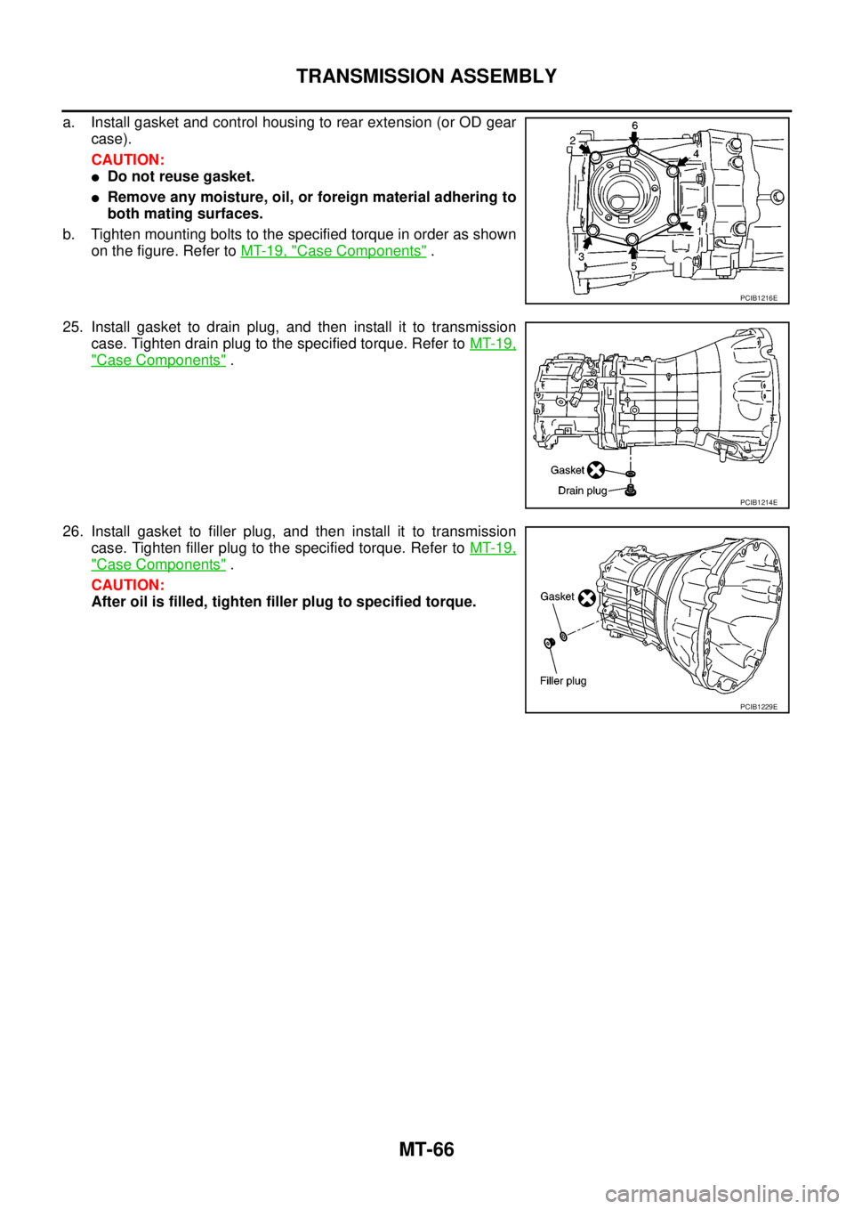
a. Install gasket and control housing to rear extension (or OD gear
case).
CAUTION:
lDo not reuse gasket.
lRemove any moisture, oil, or foreign material adhering to
both mating surfaces.
b. Tighten mounting bolts to the specified torque in order as shown
on the figure. Refer toMT-19, "
Case Components".
25. Install gasket to drain plug, and then install it to transmission
case. Tighten drain plug to the specified torque. Refer toMT-19,
"Case Components".
26. Install gasket to filler plug, and then install it to transmission
case. Tighten filler plug to the specified torque. Refer toMT-19,
"Case Components".
CAUTION:
After oil is filled, tighten filler plug to specified torque.
PCIB1216E
PCIB1214E
PCIB1229E
Page 2384 of 3171
SERVICE DATA AND SPECIFICATIONS (SDS)
MT-67
D
E
F
G
H
I
J
K
L
MA
B
MT
SERVICE DATA AND SPECIFICATIONS (SDS)PFP:00030
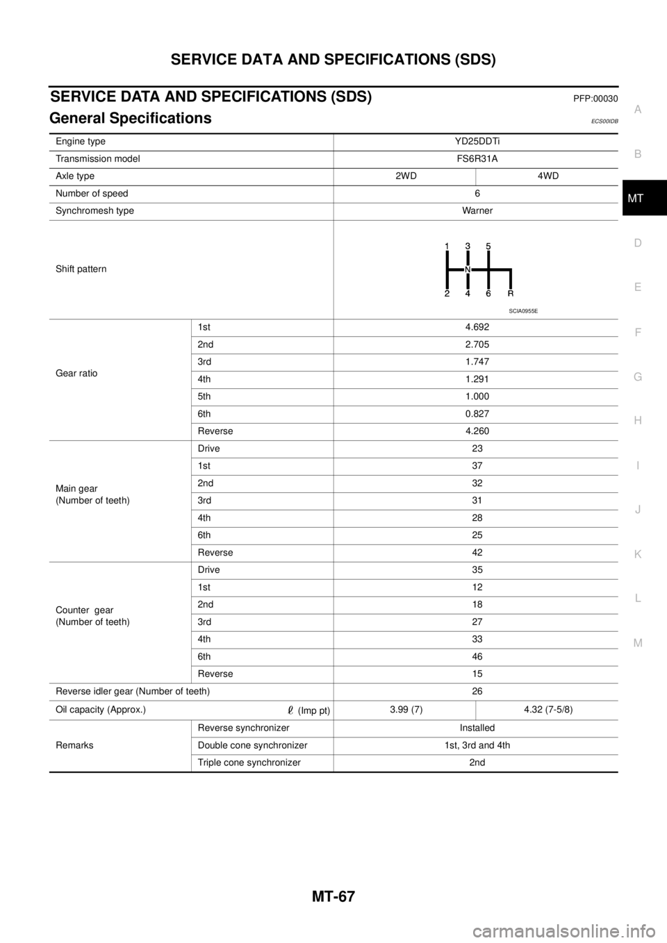
General SpecificationsECS00IDB
Engine typeYD25DDTi
Transmission modelFS6R31A
Axle type 2WD 4WD
Number of speed6
Synchromesh typeWarner
Shift pattern
Gear ratio1st 4.692
2nd 2.705
3rd 1.747
4th 1.291
5th 1.000
6th 0.827
Reverse 4.260
Main gear
(Number of teeth)Drive 23
1st 37
2nd 32
3rd 31
4th 28
6th 25
Reverse 42
Counter gear
(Number of teeth)Drive 35
1st 12
2nd 18
3rd 27
4th 33
6th 46
Reverse 15
Reverse idler gear (Number of teeth) 26
Oil capacity (Approx.)
(Imp pt)3.99 (7) 4.32 (7-5/8)
RemarksReverse synchronizer Installed
Double cone synchronizer 1st, 3rd and 4th
Triple cone synchronizer 2nd
SCIA0955E
Page 2385 of 3171

MT-68
SERVICE DATA AND SPECIFICATIONS (SDS)
Gear End Play
ECS00IDC
Unit: mm (in)
Snap RingsECS00IDD
Unit: mm (in)
*: Always check with the Parts Department for the latest parts information.Item Standard value
Counter gear0 - 0.10 (0 - 0.004)
Main drive gear0 - 0.10 (0 - 0.004)
Mainshaft (Front side) 0 - 0.10 (0 - 0.004)
Mainshaft (Rear side) 0 - 0.10 (0 - 0.004)
Selective parts Thickness Part number*
Main drive gear1.89 (0.0744)
1.95 (0.0768)
1.99 (0.0783)
2.03 (0.0799)
2.07 (0.0815)
2.11 (0.0831)32204 01G60
32204 01G61
32204 01G62
32204 01G63
32204 01G64
32204 01G65
Counter gear1.96 (0.0772)
2.02 (0.0795)
2.08 (0.0819)
2.14 (0.0843)
2.20 (0.0866)
2.26 (0.0890)
2.32 (0.0913)
2.38 (0.0937)
2.44 (0.0961)
2.50 (0.0984)
2.56 (0.1008)
2.62 (0.1031)32236 CD000
32236 CD001
32236 CD002
32236 CD003
32236 CD004
32236 CD005
32236 CD006
32236 CD007
32236 CD008
32236 CD009
32236 CD010
32236 CD011
MainshaftFront side2.08 (0.0819)
2.14 (0.0843)
2.20 (0.0866)
2.26 (0.0890)32204 CD000
32204 CD001
32204 CD002
32204 CD003
Rear side2.08 (0.0819)
2.14 (0.0843)
2.20 (0.0866)
2.26 (0.0890)
2.32 (0.0913)
2.38 (0.0937)
2.44 (0.0961)
2.50 (0.0984)
2.56 (0.1008)
2.62 (0.1031)
2.68 (0.1055)
2.74 (0.1079)
2.80 (0.1102)
2.86 (0.1126)
2.92 (0.1150)
2.98 (0.1173)32204 CD000
32204 CD001
32204 CD002
32204 CD003
32204 CD004
32204 CD005
32204 CD006
32204 CD007
32204 CD008
32204 CD009
32204 CD010
32204 CD011
32204 CD012
32204 CD013
32204 CD014
32204 CD015
Page 2386 of 3171
SERVICE DATA AND SPECIFICATIONS (SDS)
MT-69
D
E
F
G
H
I
J
K
L
MA
B
MT
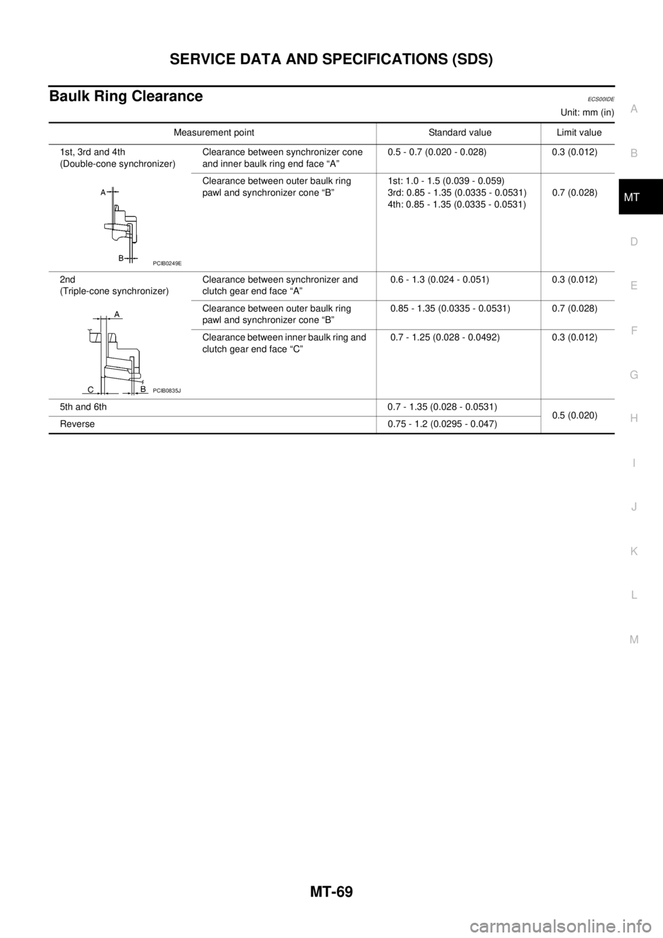
Baulk Ring ClearanceECS00IDE
Unit: mm (in)
Measurement point Standard value Limit value
1st, 3rd and 4th
(Double-cone synchronizer)Clearance between synchronizer cone
and inner baulk ring end face “A”0.5 - 0.7 (0.020 - 0.028) 0.3 (0.012)
Clearance between outer baulk ring
pawl and synchronizer cone “B”1st: 1.0 - 1.5 (0.039 - 0.059)
3rd: 0.85 - 1.35 (0.0335 - 0.0531)
4th: 0.85 - 1.35 (0.0335 - 0.0531)0.7 (0.028)
2nd
(Triple-cone synchronizer)Clearance between synchronizer and
clutch gear end face “A”0.6 - 1.3 (0.024 - 0.051) 0.3 (0.012)
Clearance between outer baulk ring
pawl and synchronizer cone “B”0.85 - 1.35 (0.0335 - 0.0531) 0.7 (0.028)
Clearance between inner baulk ring and
clutch gear end face “C”0.7 - 1.25 (0.028 - 0.0492) 0.3 (0.012)
5th and 6th 0.7 - 1.35 (0.028 - 0.0531)
0.5 (0.020)
Reverse 0.75 - 1.2 (0.0295 - 0.047)
PCIB0249E
PCIB0835J
Page 2387 of 3171

MT-70
SERVICE DATA AND SPECIFICATIONS (SDS)
Page 2388 of 3171
MTC-1
MANUAL AIR CONDITIONER
J AIR CONDITIONER
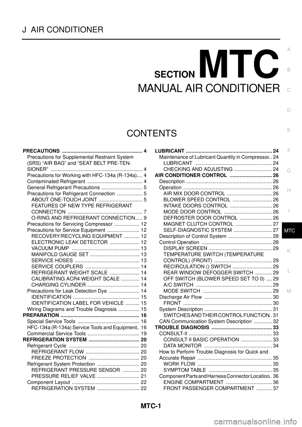
CONTENTS
C
D
E
F
G
H
I
K
L
M
SECTIONMTC
A
B
MTC
MANUAL AIR CONDITIONER
PRECAUTIONS .......................................................... 4
Precautions for Supplemental Restraint System
(SRS)“AIRBAG”and“SEATBELTPRE-TEN-
SIONER” .................................................................. 4
Precautions for Working with HFC-134a (R-134a)..... 4
Contaminated Refrigerant ........................................ 4
General Refrigerant Precautions .............................. 5
Precautions for Refrigerant Connection ................... 5
ABOUT ONE-TOUCH JOINT ................................ 5
FEATURES OF NEW TYPE REFRIGERANT
CONNECTION ...................................................... 7
O-RING AND REFRIGERANT CONNECTION..... 9
Precautions for Servicing Compressor ................... 12
Precautions for Service Equipment ........................ 12
RECOVERY/RECYCLING EQUIPMENT ............ 12
ELECTRONIC LEAK DETECTOR ...................... 12
VACUUM PUMP ................................................. 13
MANIFOLD GAUGE SET .................................... 13
SERVICE HOSES ............................................... 13
SERVICE COUPLERS ........................................ 14
REFRIGERANT WEIGHT SCALE ...................... 14
CALIBRATING ACR4 WEIGHT SCALE .............. 14
CHARGING CYLINDER ...................................... 14
Precautions for Leak Detection Dye ....................... 14
IDENTIFICATION ................................................ 15
IDENTIFICATION LABEL FOR VEHICLE ........... 15
Wiring Diagrams and Trouble Diagnosis ................ 15
PREPARATION ......................................................... 16
Special Service Tools ............................................. 16
HFC-134a (R-134a) Service Tools and Equipment... 16
Commercial Service Tools ...................................... 19
REFRIGERATION SYSTEM ..................................... 20
Refrigerant Cycle ................................................... 20
REFRIGERANT FLOW ....................................... 20
FREEZE PROTECTION ..................................... 20
Refrigerant System Protection ............................... 20
REFRIGERANT PRESSURE SENSOR ............. 20
PRESSURE RELIEF VALVE ............................... 21
Component Layout ................................................. 22
REFRIGERATION SYSTEM ............................... 22LUBRICANT .............................................................. 24
Maintenance of Lubricant Quantity in Compressor... 24
LUBRICANT ........................................................ 24
CHECKING AND ADJUSTING ............................ 24
AIR CONDITIONER CONTROL ............................... 26
Description .............................................................. 26
Operation ................................................................ 26
AIR MIX DOOR CONTROL ................................. 26
BLOWER SPEED CONTROL ............................. 26
INTAKE DOORS CONTROL ............................... 26
MODE DOOR CONTROL ................................... 26
DEFROSTER DOOR CONTROL ........................ 26
MAGNET CLUTCH CONTROL ........................... 27
SELF-DIAGNOSTIC SYSTEM ............................ 27
Description of Control System ................................ 28
Control Operation ................................................... 28
DISPLAY SCREEN .............................................. 29
TEMPERATURE SWITCH (TEMPERATURE
CONTROL) (FRONT) .......................................... 29
RECIRCULATION () SWITCH ............................. 29
REAR WINDOW DEFOGGER SWITCH ............. 29
OFF SWITCH (BLOWER SPEED SET TO 0) ..... 29
A/C SWITCH ....................................................... 29
MODE SWITCH .................................................. 29
Discharge Air Flow ................................................. 30
FRONT ................................................................ 30
System Description ................................................. 31
SWITCHES AND THEIR CONTROL FUNCTION... 31
CAN Communication System Description .............. 32
TROUBLE DIAGNOSIS ............................................ 33
CONSULT-II ............................................................ 33
CONSULT-II BASIC OPERATION ....................... 33
DATA MONITOR ................................................. 34
How to Perform Trouble Diagnosis for Quick and
Accurate Repair ...................................................... 35
WORK FLOW ...................................................... 35
SYMPTOM TABLE .............................................. 35
Component Parts and Harness Connector Location... 36
ENGINE COMPARTMENT .................................. 36
FRONT PASSENGER COMPARTMENT ............ 37
Page 2389 of 3171

MTC-2
Schematic —LHD MODELS— ............................... 38
Wiring Diagram —A/C— —LHD MODELS— ......... 39
Schematic —RHD MODELS— ............................... 44
Wiring Diagram —A/C— —RHD MODELS— ......... 45
Front Air Control Terminals and Reference Value... 49
PIN CONNECTOR TERMINAL LAYOUT ............ 49
TERMINALS AND REFERENCE VALUE FOR
FRONT AIR CONTROL ....................................... 49
A/C System Self-diagnosis Function ...................... 51
DESCRIPTION .................................................... 51
Operational Check .................................................. 53
CHECKING BLOWER ......................................... 53
CHECKING DISCHARGE AIR ............................ 53
CHECKING RECIRCULATION ............................ 53
CHECKING TEMPERATURE DECREASE ......... 54
CHECKING TEMPERATURE INCREASE .......... 54
CHECK A/C SWITCH .......................................... 54
Power Supply and Ground Circuit for Front Air Con-
trol ........................................................................... 55
INSPECTION FLOW ........................................... 55
COMPONENT DESCRIPTION ............................ 56
DIAGNOSTIC PROCEDURE FOR A/C SYSTEM... 56
Mode Door Motor Circuit ........................................ 58
INSPECTION FLOW ........................................... 58
SYSTEM DESCRIPTION .................................... 59
COMPONENT DESCRIPTION ............................ 59
DIAGNOSTIC PROCEDURE FOR MODE
DOOR MOTOR ................................................... 59
Air Mix Door Motor Circuit ...................................... 63
INSPECTION FLOW ........................................... 63
SYSTEM DESCRIPTION .................................... 64
COMPONENT DESCRIPTION ............................ 64
DIAGNOSTIC PROCEDURE FOR AIR MIX
DOOR MOTOR (FRONT) .................................... 64
Intake Door Motor Circuit ........................................ 68
INSPECTION FLOW ........................................... 68
SYSTEM DESCRIPTION .................................... 69
COMPONENT DESCRIPTION ............................ 69
DIAGNOSTIC PROCEDURE FOR INTAKE
DOOR MOTOR ................................................... 69
Blower Motor Circuit ............................................... 71
INSPECTION FLOW ........................................... 71
SYSTEM DESCRIPTION .................................... 72
COMPONENT DESCRIPTION ............................ 72
DIAGNOSTIC PROCEDURE FOR BLOWER
MOTOR ............................................................... 73
COMPONENT INSPECTION .............................. 77
Magnet Clutch Circuit ............................................. 79
INSPECTION FLOW ........................................... 79
SYSTEM DESCRIPTION .................................... 80
DIAGNOSTIC PROCEDURE FOR MAGNET
CLUTCH .............................................................. 80
COMPONENT INSPECTION .............................. 85
Insufficient Cooling ................................................. 86
INSPECTION FLOW ........................................... 86
PERFORMANCE TEST DIAGNOSES ................ 87
PERFORMANCE CHART ................................... 89
TROUBLE DIAGNOSES FOR UNUSUAL PRES-
SURE ................................................................... 90Insufficient Heating ................................................. 93
INSPECTION FLOW ............................................ 93
Noise ....................................................................... 94
INSPECTION FLOW ............................................ 94
Self-diagnosis ......................................................... 95
INSPECTION FLOW ............................................ 95
Intake Sensor Circuit ............................................... 95
COMPONENT DESCRIPTION ............................ 95
DIAGNOSTIC PROCEDURE FOR INTAKE SEN-
SOR ..................................................................... 96
COMPONENT INSPECTION ............................... 97
CONTROL UNIT ........................................................ 98
Removal and Installation ......................................... 98
REMOVAL ............................................................ 98
INSTALLATION .................................................... 98
INTAKE SENSOR ...................................................... 99
Removal and Installation ......................................... 99
REMOVAL ............................................................ 99
INSTALLATION .................................................... 99
BLOWER MOTOR ...................................................100
Components ..........................................................100
Removal and Installation .......................................100
REMOVAL ..........................................................100
INSTALLATION ..................................................100
AIR CONDITIONER FILTER ...................................101
Removal and Installation .......................................101
FUNCTION ........................................................101
REPLACEMENT TIMING ..................................101
REPLACEMENT PROCEDURE ........................101
HEATER & COOLING UNIT ASSEMBLY ...............103
Components ..........................................................103
Removal and Installation .......................................105
REMOVAL ..........................................................105
INSTALLATION ..................................................105
HEATER CORE .......................................................106
Components ..........................................................106
Removal and Installation .......................................107
REMOVAL ..........................................................107
INSTALLATION ..................................................107
DEFROSTER DOOR MOTOR .................................108
Components ..........................................................108
Removal and Installation .......................................108
REMOVAL ..........................................................108
INSTALLATION ..................................................108
INTAKE DOOR MOTOR ..........................................109
Components ..........................................................109
Removal and Installation .......................................109
REMOVAL ..........................................................109
INSTALLATION ..................................................109
MODE DOOR MOTOR ............................................110
Components ..........................................................110
Removal and Installation .......................................110
REMOVAL ..........................................................110
INSTALLATION ..................................................110
AIR MIX DOOR MOTOR ......................................... 111
Components .......................................................... 111
Removal and Installation ....................................... 111
REMOVAL .......................................................... 111
INSTALLATION .................................................. 111
Page 2390 of 3171

MTC-3
C
D
E
F
G
H
I
K
L
MA
B
MTC BLOWER MOTOR RESISTOR ................................112
Components .......................................................... 112
Removal and Installation ....................................... 112
REMOVAL .......................................................... 112
INSTALLATION .................................................. 112
DUCTS AND GRILLES ...........................................113
Components .......................................................... 113
Removal and Installation ....................................... 116
CENTER CONSOLE HEAT DUCT AND REAR
FINISHER ASSEMBLY GRILLE ........................ 116
DEFROSTER NOZZLE ...................................... 116
RH AND LH SIDE DEMISTER DUCT ................ 116
RH AND LH VENTILATOR DUCT ...................... 116
CENTER VENTILATOR DUCT .......................... 116
FLOOR DUCT .................................................... 116
GRILLES ............................................................ 116
REFRIGERANT LINES ............................................118
HFC-134a (R-134a) Service Procedure ................ 118
SETTING OF SERVICE TOOLS AND EQUIP-
MENT ................................................................. 118
Components ......................................................... 120
Removal and Installation for Compressor ............ 122
REMOVAL ......................................................... 122
INSTALLATION ................................................. 122
Removal and Installation for Compressor Clutch . 123
REMOVAL ......................................................... 123
INSPECTION .................................................... 124
INSTALLATION ................................................. 124
BREAK-IN OPERATION ................................... 126
Removal and Installation for Low-pressure Flexible
Hose ..................................................................... 126
REMOVAL ......................................................... 126
INSTALLATION ................................................. 126
Removal and Installation for High-pressure Flexible
Hose ..................................................................... 126
REMOVAL ......................................................... 126INSTALLATION .................................................126
Removal and Installation for High-pressure Pipe . 126
REMOVAL .........................................................126
INSTALLATION .................................................126
Removal and Installation for Low-pressure Pipe ..127
REMOVAL .........................................................127
INSTALLATION .................................................127
Removal and Installation for Refrigerant Pressure
Sensor ..................................................................127
REMOVAL .........................................................127
INSTALLATION .................................................127
Removal and Installation for Condenser ..............127
REMOVAL .........................................................127
INSTALLATION .................................................128
Removal and Installation for Evaporator ..............129
REMOVAL .........................................................130
INSTALLATION .................................................130
Removal and Installation for Expansion Valve ......130
REMOVAL .........................................................130
INSTALLATION .................................................130
Checking for Refrigerant Leaks ............................131
Checking System for Leaks Using the Fluorescent
Leak Detector .......................................................131
Dye Injection .........................................................131
Electronic Refrigerant Leak Detector ....................132
PRECAUTIONS FOR HANDLING LEAK
DETECTOR .......................................................132
CHECKING PROCEDURE ...............................133
SERVICE DATA AND SPECIFICATIONS (SDS) ....135
Service Data and Specifications (SDS) ................135
COMPRESSOR ................................................135
LUBRICANT ......................................................135
REFRIGERANT .................................................135
ENGINE IDLING SPEED ..................................135
BELT TENSION .................................................135