NISSAN NAVARA 2005 Repair Workshop Manual
NAVARA 2005
NISSAN
NISSAN
https://www.carmanualsonline.info/img/5/57362/w960_57362-0.png
NISSAN NAVARA 2005 Repair Workshop Manual
Trending: power windows, service schedule, towing capacity, lug pattern, belt, reset, interior lights
Page 2341 of 3171
MT-24
TRANSMISSION ASSEMBLY
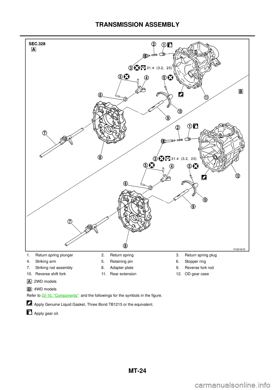
1. Return spring plunger 2. Return spring 3. Return spring plug
4. Striking arm 5. Retaining pin 6. Stopper ring
7. Striking rod assembly 8. Adapter plate 9. Reverse fork rod
10. Reverse shift fork 11. Rear extension 12. OD gear case
: 2WD models
: 4WD models
Refer toGI-10, "
Components"and the followings for the symbols in the figure.
: Apply Genuine Liquid Gasket, Three Bond TB1215 or the equivalent.
: Apply gear oil.
PCIB1657E
Page 2342 of 3171
TRANSMISSION ASSEMBLY
MT-25
D
E
F
G
H
I
J
K
L
MA
B
MT
DISASSEMBLY
Case Components
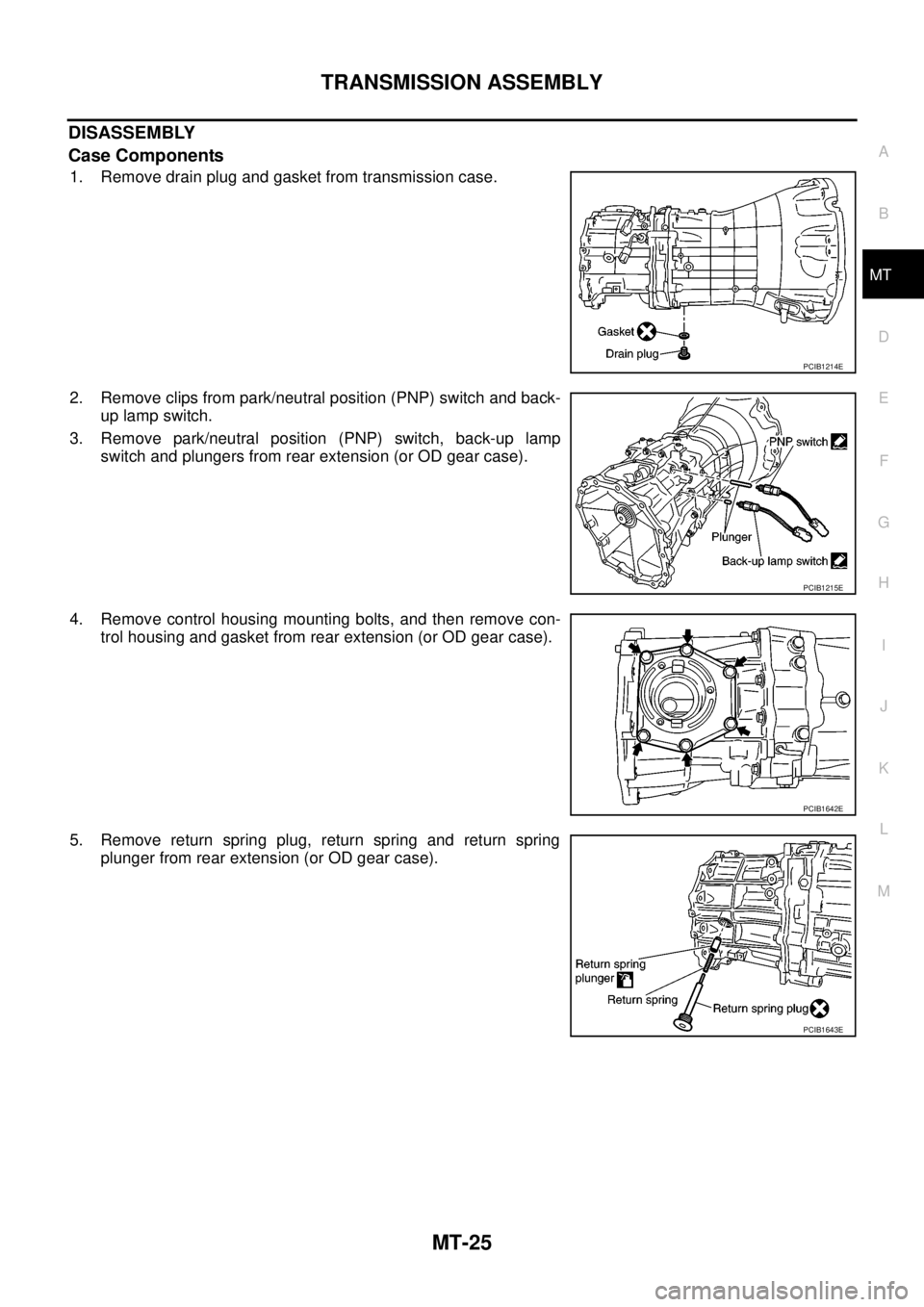
1. Remove drain plug and gasket from transmission case.
2. Remove clips from park/neutral position (PNP) switch and back-
up lamp switch.
3. Remove park/neutral position (PNP) switch, back-up lamp
switch and plungers from rear extension (or OD gear case).
4. Remove control housing mounting bolts, and then remove con-
trol housing and gasket from rear extension (or OD gear case).
5. Remove return spring plug, return spring and return spring
plunger from rear extension (or OD gear case).
PCIB1214E
PCIB1215E
PCIB1642E
PCIB1643E
Page 2343 of 3171
MT-26
TRANSMISSION ASSEMBLY
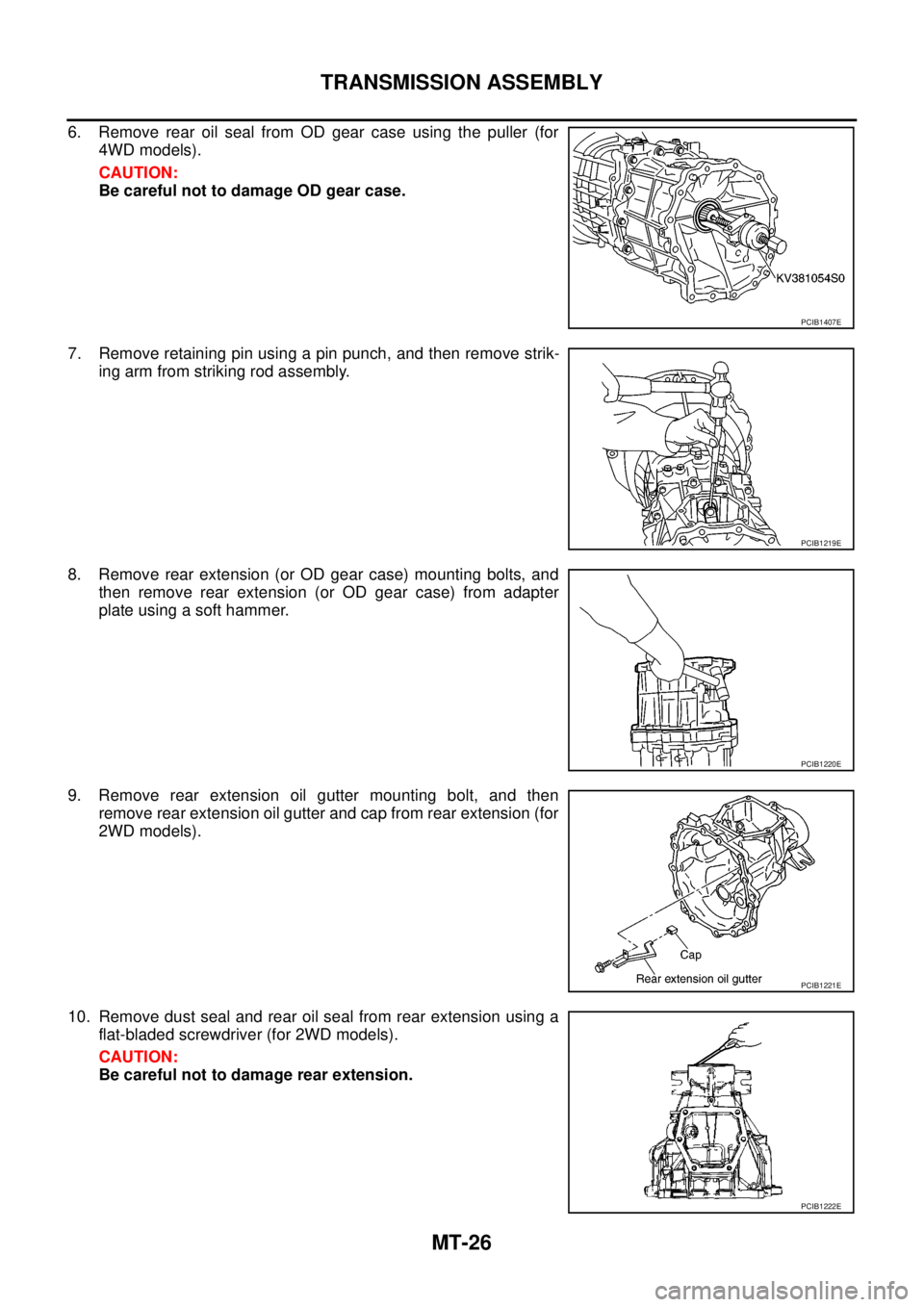
6. Remove rear oil seal from OD gear case using the puller (for
4WD models).
CAUTION:
Be careful not to damage OD gear case.
7. Remove retaining pin using a pin punch, and then remove strik-
ing arm from striking rod assembly.
8. Remove rear extension (or OD gear case) mounting bolts, and
then remove rear extension (or OD gear case) from adapter
plate using a soft hammer.
9. Remove rear extension oil gutter mounting bolt, and then
remove rear extension oil gutter and cap from rear extension (for
2WD models).
10. Remove dust seal and rear oil seal from rear extension using a
flat-bladed screwdriver (for 2WD models).
CAUTION:
Be careful not to damage rear extension.
PCIB1407E
PCIB1219E
PCIB1220E
PCIB1221E
PCIB1222E
Page 2344 of 3171
TRANSMISSION ASSEMBLY
MT-27
D
E
F
G
H
I
J
K
L
MA
B
MT
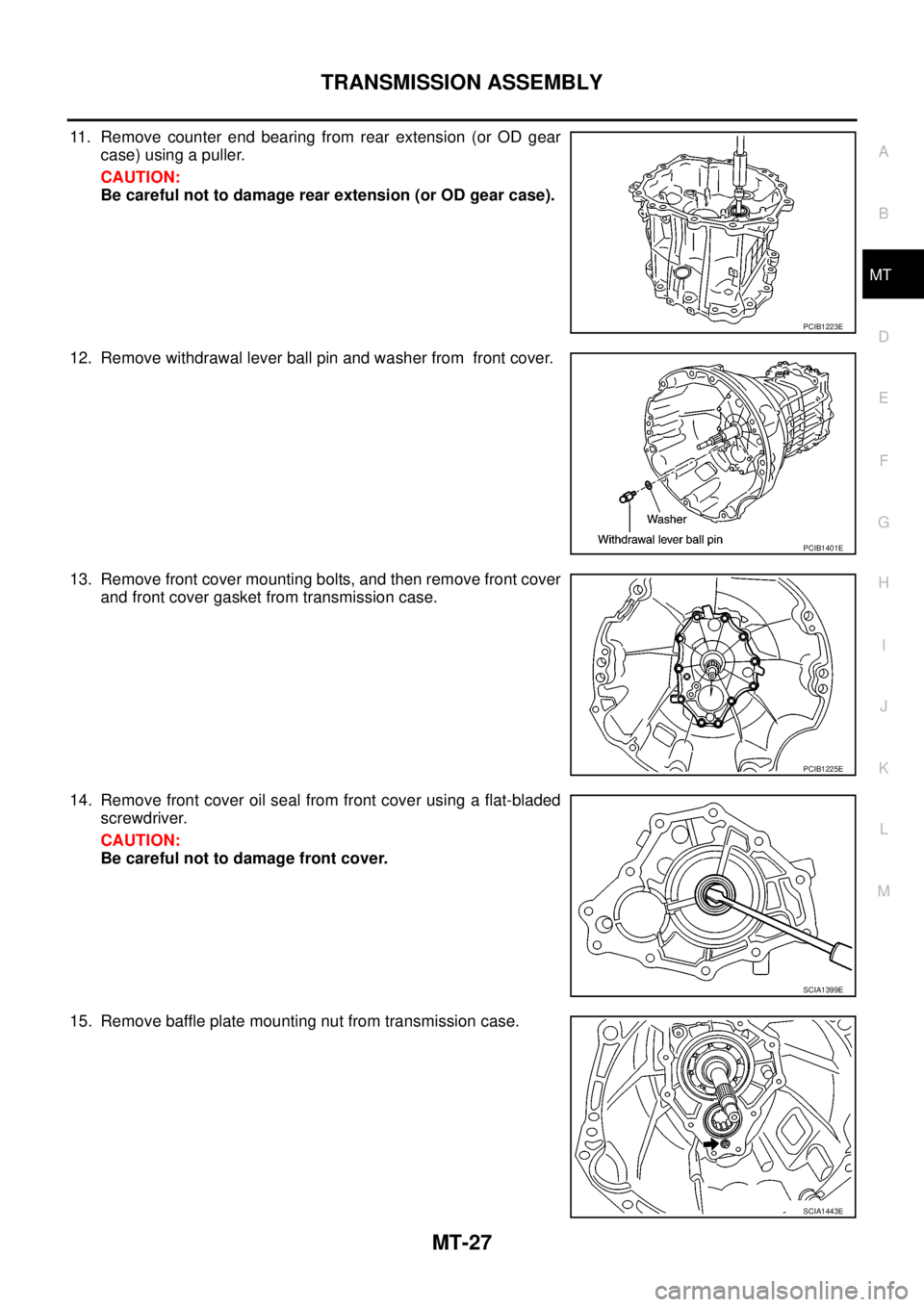
11. Remove counter end bearing from rear extension (or OD gear
case) using a puller.
CAUTION:
Be careful not to damage rear extension (or OD gear case).
12. Remove withdrawal lever ball pin and washer from front cover.
13. Remove front cover mounting bolts, and then remove front cover
and front cover gasket from transmission case.
14. Remove front cover oil seal from front cover using a flat-bladed
screwdriver.
CAUTION:
Be careful not to damage front cover.
15. Remove baffle plate mounting nut from transmission case.
PCIB1223E
PCIB1401E
PCIB1225E
SCIA1399E
SCIA1443E
Page 2345 of 3171
MT-28
TRANSMISSION ASSEMBLY
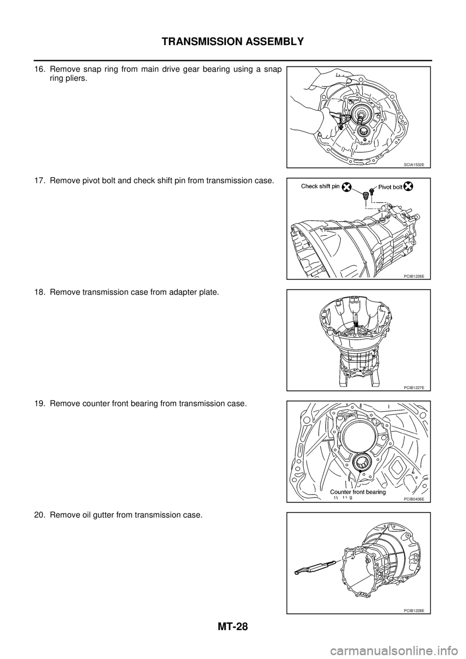
16. Remove snap ring from main drive gear bearing using a snap
ring pliers.
17. Remove pivot bolt and check shift pin from transmission case.
18. Remove transmission case from adapter plate.
19. Remove counter front bearing from transmission case.
20. Remove oil gutter from transmission case.
SCIA1532E
PCIB1226E
PCIB1227E
PCIB0436E
PCIB1228E
Page 2346 of 3171
TRANSMISSION ASSEMBLY
MT-29
D
E
F
G
H
I
J
K
L
MA
B
MT
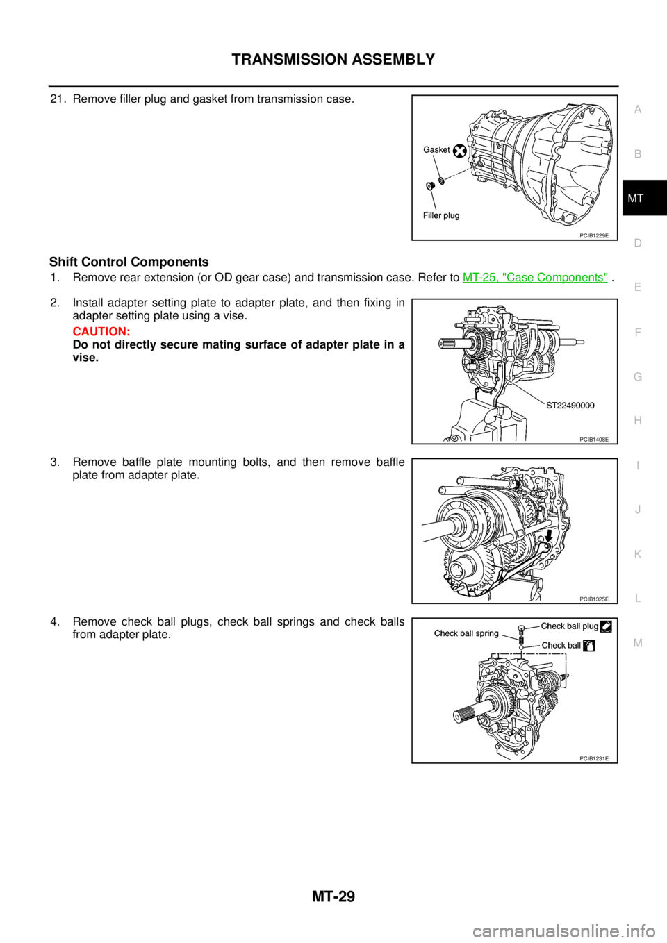
21. Remove filler plug and gasket from transmission case.
Shift Control Components
1. Remove rear extension (or OD gear case) and transmission case. Refer toMT-25, "Case Components".
2. Install adapter setting plate to adapter plate, and then fixing in
adapter setting plate using a vise.
CAUTION:
Do not directly secure mating surface of adapter plate in a
vise.
3. Remove baffle plate mounting bolts, and then remove baffle
plate from adapter plate.
4. Remove check ball plugs, check ball springs and check balls
from adapter plate.
PCIB1229E
PCIB1408E
PCIB1325E
PCIB1231E
Page 2347 of 3171
MT-30
TRANSMISSION ASSEMBLY
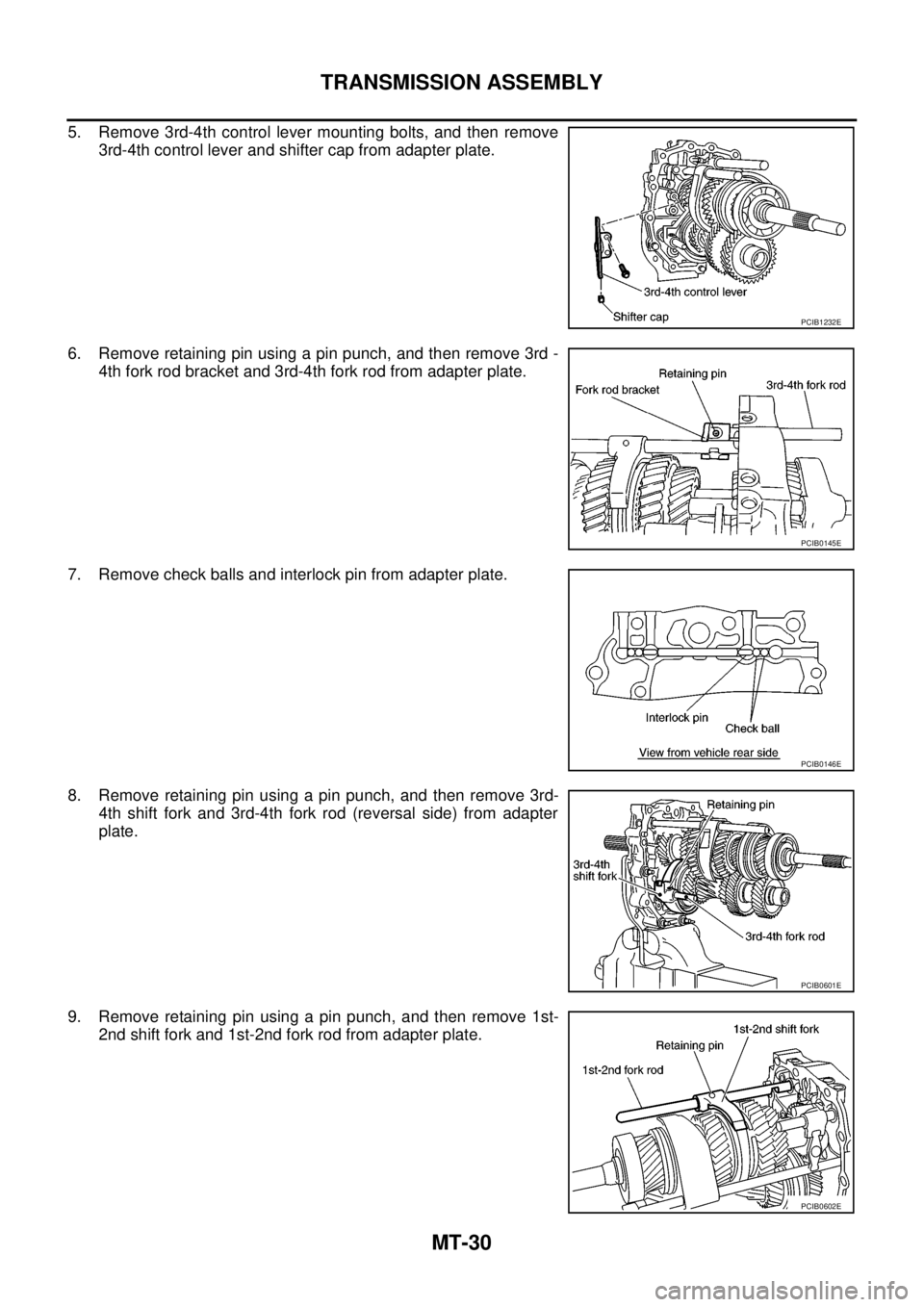
5. Remove 3rd-4th control lever mounting bolts, and then remove
3rd-4th control lever and shifter cap from adapter plate.
6. Remove retaining pin using a pin punch, and then remove 3rd -
4th fork rod bracket and 3rd-4th fork rod from adapter plate.
7. Remove check balls and interlock pin from adapter plate.
8. Remove retaining pin using a pin punch, and then remove 3rd-
4th shift fork and 3rd-4th fork rod (reversal side) from adapter
plate.
9. Remove retaining pin using a pin punch, and then remove 1st-
2nd shift fork and 1st-2nd fork rod from adapter plate.
PCIB1232E
PCIB0145E
PCIB0146E
PCIB0601E
PCIB0602E
Page 2348 of 3171
TRANSMISSION ASSEMBLY
MT-31
D
E
F
G
H
I
J
K
L
MA
B
MT
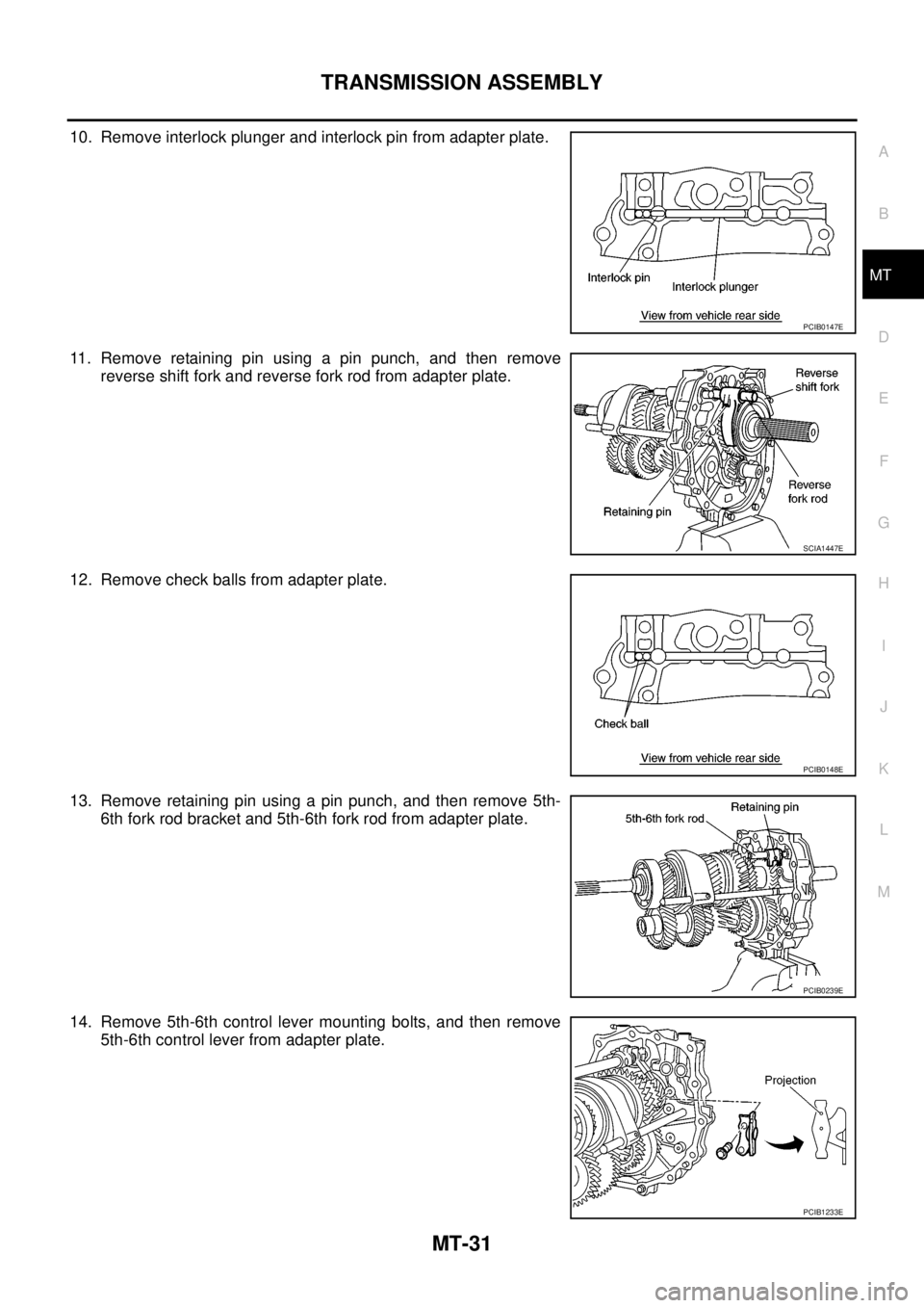
10. Remove interlock plunger and interlock pin from adapter plate.
11. Remove retaining pin using a pin punch, and then remove
reverse shift fork and reverse fork rod from adapter plate.
12. Remove check balls from adapter plate.
13. Remove retaining pin using a pin punch, and then remove 5th-
6th fork rod bracket and 5th-6th fork rod from adapter plate.
14. Remove 5th-6th control lever mounting bolts, and then remove
5th-6th control lever from adapter plate.
PCIB0147E
SCIA1447E
PCIB0148E
PCIB0239E
PCIB1233E
Page 2349 of 3171
MT-32
TRANSMISSION ASSEMBLY
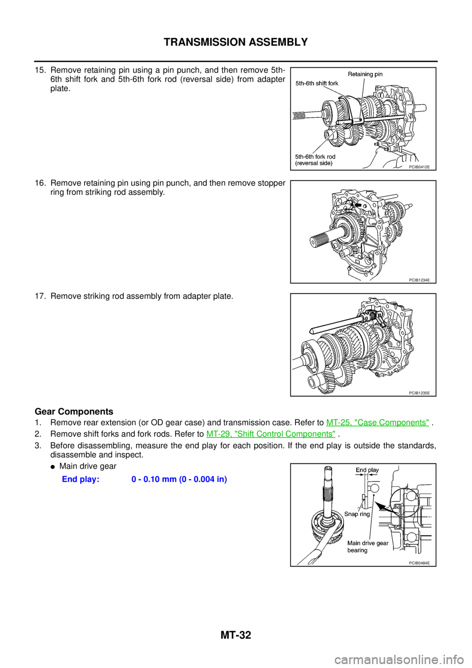
15. Remove retaining pin using a pin punch, and then remove 5th-
6th shift fork and 5th-6th fork rod (reversal side) from adapter
plate.
16. Remove retaining pin using pin punch, and then remove stopper
ring from striking rod assembly.
17. Remove striking rod assembly from adapter plate.
Gear Components
1. Remove rear extension (or OD gear case) and transmission case. Refer toMT-25, "Case Components".
2. Remove shift forks and fork rods. Refer toMT-29, "
Shift Control Components".
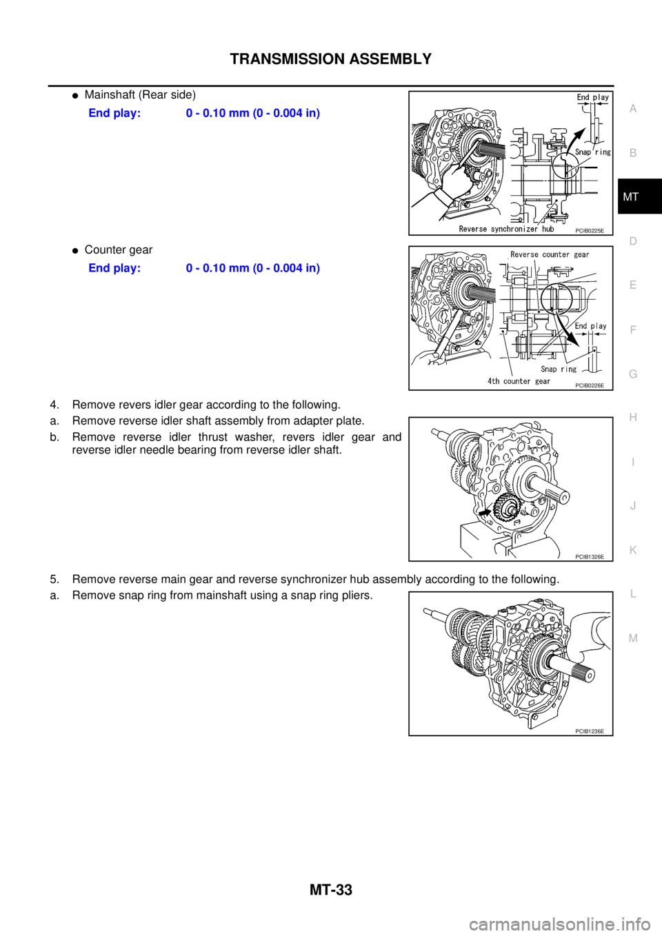
3. Before disassembling, measure the end play for each position. If the end play is outside the standards,
disassemble and inspect.
lMain drive gear
PCIB0412E
PCIB1234E
PCIB1235E
End play: 0 - 0.10 mm (0 - 0.004 in)
PCIB0484E
Page 2350 of 3171
TRANSMISSION ASSEMBLY
MT-33
D
E
F
G
H
I
J
K
L
MA
B
MT
lMainshaft (Rear side)
lCounter gear
4. Remove revers idler gear according to the following.
a. Remove reverse idler shaft assembly from adapter plate.
b. Remove reverse idler thrust washer, revers idler gear and
reverse idler needle bearing from reverse idler shaft.
5. Remove reverse main gear and reverse synchronizer hub assembly according to the following.
a. Remove snap ring from mainshaft using a snap ring pliers.End play: 0 - 0.10 mm (0 - 0.004 in)
PCIB0225E
End play: 0 - 0.10 mm (0 - 0.004 in)
PCIB0226E
PCIB1326E
PCIB1236E
Trending: maintenance schedule, child seat, headlights, battery capacity, height adjustment, tow, child restraint
