NISSAN NAVARA 2005 Repair Workshop Manual
Manufacturer: NISSAN, Model Year: 2005, Model line: NAVARA, Model: NISSAN NAVARA 2005Pages: 3171, PDF Size: 49.59 MB
Page 3141 of 3171
WW-30
FRONT WIPER AND WASHER SYSTEM
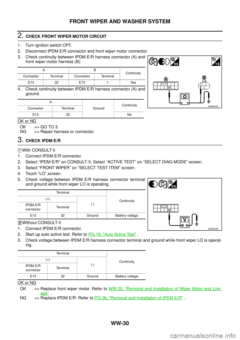
2.CHECK FRONT WIPER MOTOR CIRCUIT
1. Turn ignition switch OFF.
2. Disconnect IPDM E/R connector and front wiper motor connector.
3. Check continuity between IPDM E/R harness connector (A) and
front wiper motor harness (B).
4. Check continuity between IPDM E/R harness connector (A) and
ground.
OK or NG
OK >> GO TO 3.
NG >> Repair harness or connector.
3.CHECK IPDM E/R
With CONSULT-ll
1. Connect IPDM E/R connector.
2. Select “IPDM E/R” on CONSULT-II. Select “ACTIVE TEST” on “SELECT DIAG MODE” screen.
3. Select “FRONT WIPER” on “SELECT TEST ITEM” screen.
4. Touch “LO” screen.
5. Check voltage between IPDM E/R harness connector terminal
and ground while front wiper LO is operating.
Without CONSULT-ll
1. Connect IPDM E/R connector.
2. Startupautoactivetest.RefertoPG-19, "
Auto Active Test".
3. Check voltage between IPDM E/R harness connector terminal and ground while front wiper LO is operat-
ing.
OK or NG
OK >> Replace front wiper motor. Refer toWW-35, "Removal and Installation of Wiper Motor and Link-
age".
NG >> Replace IPDM E/R. Refer toPG-26, "
Removal and Installation of IPDM E/R".
AB
Continuity
Connector Terminal Connector Terminal
E13 32 E72 1 Yes
A
GroundContinuity
Connector Terminal
E13 32 No
SKIB6230E
Terminal
Continuity (+)
(-)
IPDM E/R
connectorTerminal
E13 32 Ground Battery voltage
Terminal
Continuity (+)
(-)
IPDM E/R
connectorTerminal
E13 32 Ground Battery voltage
SKIB6229E
Page 3142 of 3171
FRONT WIPER AND WASHER SYSTEM
WW-31
C
D
E
F
G
H
I
J
L
MA
B
WW
Only Front Wiper HI Does Not OperateEKS00P59
1.ACTIVE TEST
With CONSULT-ll
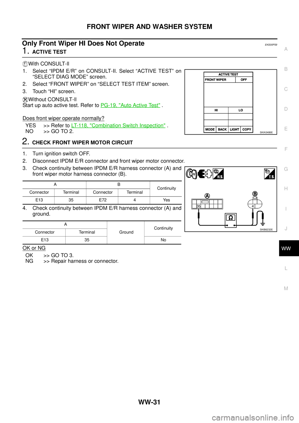
1. Select “IPDM E/R” on CONSULT-II. Select “ACTIVE TEST” on
“SELECT DIAG MODE” screen.
2. Select “FRONT WIPER” on “SELECT TEST ITEM” screen.
3. Touch “HI” screen.
Without CONSULT-ll
Start up auto active test. Refer toPG-19, "
Auto Active Test".
Does front wiper operate normally?
YES >> Refer toLT- 11 8 , "Combination Switch Inspection".
NO >> GO TO 2.
2.CHECK FRONT WIPER MOTOR CIRCUIT
1. Turn ignition switch OFF.
2. Disconnect IPDM E/R connector and front wiper motor connector.
3. Check continuity between IPDM E/R harness connector (A) and
front wiper motor harness connector (B).
4. Check continuity between IPDM E/R harness connector (A) and
ground.
OK or NG
OK >> GO TO 3.
NG >> Repair harness or connector.
SKIA3486E
AB
Continuity
Connector Terminal Connector Terminal
E13 35 E72 4 Yes
A
GroundContinuity
Connector Terminal
E13 35 No
SKIB6232E
Page 3143 of 3171
WW-32
FRONT WIPER AND WASHER SYSTEM
3.CHECK IPDM E/R
With CONSULT-ll
1. Connect IPDM E/R connector.
2. Select “IPDM E/R” on CONSULT-II. Select “ACTIVE TEST” on “SELECT DIAG MODE” screen.
3. Select “FRONT WIPER” on “SELECT TEST ITEM” screen.
4. Touch “HI” screen.
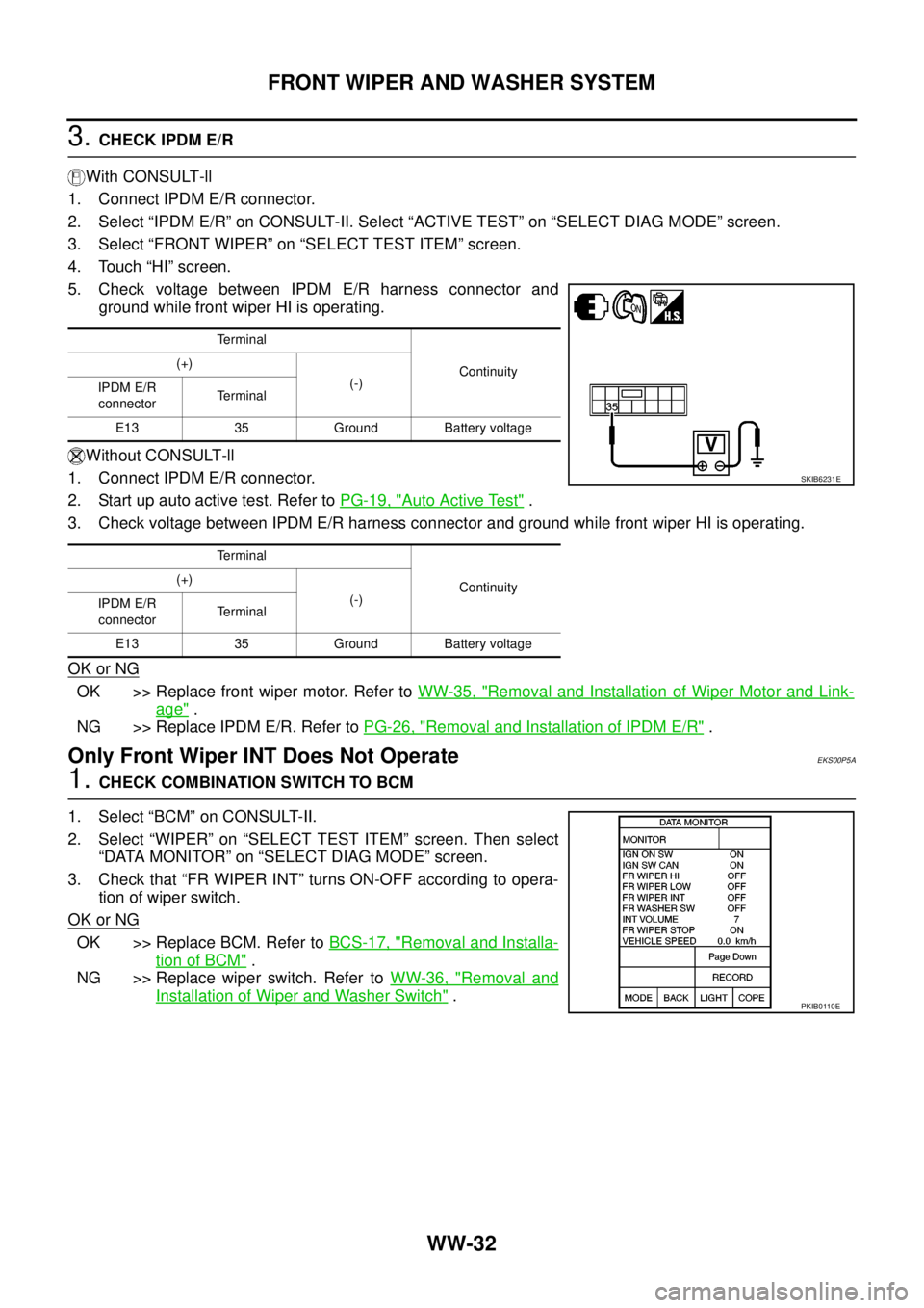
5. Check voltage between IPDM E/R harness connector and
ground while front wiper HI is operating.
Without CONSULT-ll
1. Connect IPDM E/R connector.
2. Startupautoactivetest.RefertoPG-19, "
Auto Active Test".
3. Check voltage between IPDM E/R harness connector and ground while front wiper HI is operating.
OK or NG
OK >> Replace front wiper motor. Refer toWW-35, "Removal and Installation of Wiper Motor and Link-
age".
NG >> Replace IPDM E/R. Refer toPG-26, "
Removal and Installation of IPDM E/R".
Only Front Wiper INT Does Not OperateEKS00P5A
1.CHECK COMBINATION SWITCH TO BCM
1. Select “BCM” on CONSULT-II.
2. Select “WIPER” on “SELECT TEST ITEM” screen. Then select
“DATA MONITOR” on “SELECT DIAG MODE” screen.
3. Check that “FR WIPER INT” turns ON-OFF according to opera-
tion of wiper switch.
OK or NG
OK >> Replace BCM. Refer toBCS-17, "Removal and Installa-
tion of BCM".
NG >> Replace wiper switch. Refer toWW-36, "
Removal and
Installation of Wiper and Washer Switch".
Terminal
Continuity (+)
(-)
IPDM E/R
connectorTerminal
E13 35 Ground Battery voltage
Terminal
Continuity (+)
(-)
IPDM E/R
connectorTerminal
E13 35 Ground Battery voltage
SKIB6231E
PKIB0110E
Page 3144 of 3171
FRONT WIPER AND WASHER SYSTEM
WW-33
C
D
E
F
G
H
I
J
L
MA
B
WW
Front Wiper Intermittent Operation Switch Position Cannot Be AdjustedEKS00P5B
1.CHECK COMBINATION SWITCH TO BCM
1. Select “BCM” on CONSULT-II.
2. Select “WIPER” on “SELECT TEST ITEM” screen. Then select
“DATA MONITOR” on “SELECT DIAG MODE” screen.
3. Check that “INT VOLUME” changes in order from 1 to 7 accord-
ing to operation of the intermittent switch dial position.
OK or NG
OK >> Replace BCM. Refer toBCS-17, "Removal and Installa-
tion of BCM".
NG >> Replace wiper switch. Refer toWW-36, "
Removal and
Installation of Wiper and Washer Switch".
Front Wiper Interval Time Is Not Controlled by Vehicle SpeedEKS00P5C
1.CHECK FUNCTION OF COMBINATION METER
Confirm that speedometer operates normally.
Does the front wiper operate normally?
YES >> GO TO 2.
NO >> Combination meter vehicle speed system malfunction. Refer toDI-20, "
Vehicle Speed Signal
Inspection".
2.CHECK CAN COMMUNICATION BETWEEN BCM AND COMBINATION METER
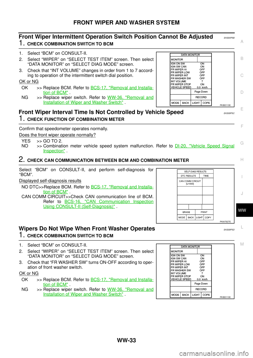
Select “BCM” on CONSULT-II, and perform self-diagnosis for
“BCM”.
Displayed self
-diagnosis results
NO DTC>>Replace BCM. Refer toBCS-17, "Removal and Installa-
tion of BCM".
CAN COMM CIRCUIT>>Check CAN communication line of BCM.
Refer toBCS-16, "
CAN Communication Inspection
Using CONSULT-II (Self-Diagnosis)".
Wipers Do Not Wipe When Front Washer OperatesEKS00P5D
1.CHECK COMBINATION SWITCH TO BCM
1. Select “BCM” on CONSULT-II.
2. Select “WIPER” on “SELECT TEST ITEM” screen. Then select
“DATA MONITOR” on “SELECT DIAG MODE” screen.
3. Check that “FR WASHER SW” turns ON-OFF according to oper-
ation of front washer switch.
OK or NG
OK >> Replace BCM. Refer toBCS-17, "Removal and Installa-
tion of BCM".
NG >> Replace wiper switch. Refer toWW-36, "
Removal and
Installation of Wiper and Washer Switch".
PKIB0110E
PKIA7627E
PKIB0110E
Page 3145 of 3171
WW-34
FRONT WIPER AND WASHER SYSTEM
Removal and Installation of Front Wiper Arms, Adjustment of Wiper Arms Stop
Location
EKS00P5E
REMOVAL
1. Operate wiper motor, and stop it at the auto stop position.
2. Remove wiper arm mounting nuts covers.
3. Remove wiper arm mounting nuts, then remove wiper arms.
INSTALLATION
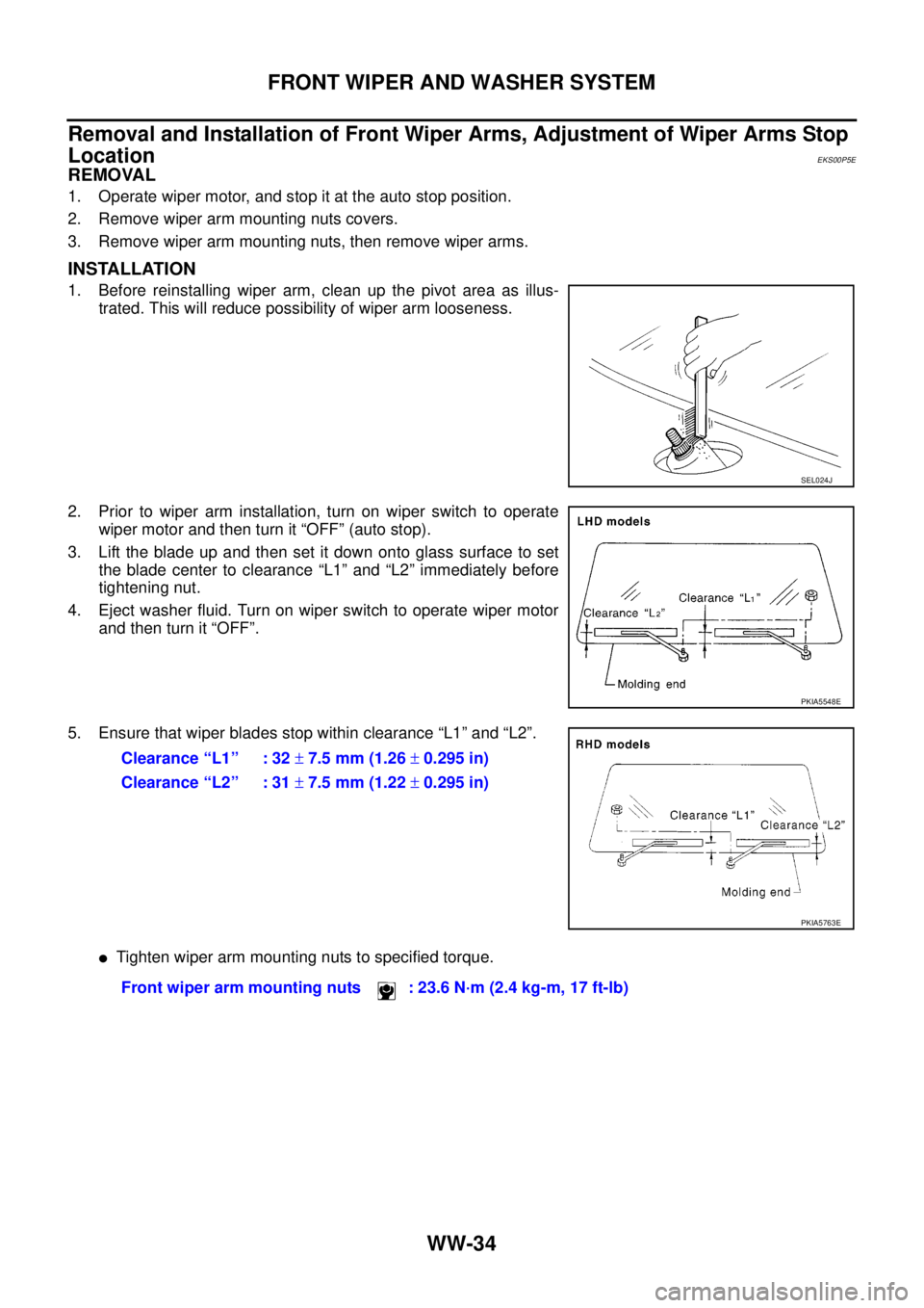
1. Before reinstalling wiper arm, clean up the pivot area as illus-
trated. This will reduce possibility of wiper arm looseness.
2. Prior to wiper arm installation, turn on wiper switch to operate
wiper motor and then turn it “OFF” (auto stop).
3. Lift the blade up and then set it down onto glass surface to set
the blade center to clearance “L1” and “L2” immediately before
tightening nut.
4. Eject washer fluid. Turn on wiper switch to operate wiper motor
and then turn it “OFF”.
5. Ensure that wiper blades stop within clearance “L1” and “L2”.
lTighten wiper arm mounting nuts to specified torque.
SEL024J
PKIA5548E
Clearance “L1” : 32±7.5 mm (1.26±0.295 in)
Clearance “L2” : 31±7.5 mm (1.22±0.295 in)
PKIA5763E
Front wiper arm mounting nuts : 23.6 N·m (2.4 kg-m, 17 ft-lb)
Page 3146 of 3171
FRONT WIPER AND WASHER SYSTEM
WW-35
C
D
E
F
G
H
I
J
L
MA
B
WW
Removal and Installation of Wiper Motor and LinkageEKS00P5F
REMOVAL
1. Turn wiper switch ON to operate wiper motor, then turn wiper switch OFF (auto stop).
2. Remove cowl top cover. Refer toEI-20, "
COWL TOP".
3. Disconnect front wiper motor connector.
4. Remove wiper frame assembly mounting bolts, and remove
wiper frame assembly.
5. Remove wiper motor to linkage nut and washer from wiper
motor pivot.
6. Remove wiper motor from wiper frame assembly.
INSTALLATION
CAUTION:
lNever drop the wiper motor or cause it to contact other parts.
lCheck the grease conditions of the motor arm and wiper link joint(s). Apply grease if necessary.
1. Connect wiper motor to connector. Turn wiper switch ON to operate wiper motor, then turn wiper switch
OFF (auto stop).
2. Disconnect wiper motor connector.
3. Install link to wiper motor pivot with nut and washer.
4. Install wiper motor to wiper frame assembly, and install assembly into the vehicle.
5. Connect wiper motor connector. Turn wiper switch ON to operate wiper motor, then turn wiper switch OFF
(auto stop).
6. Install cowl top cover. Refer toEI-20, "
COWL TOP".
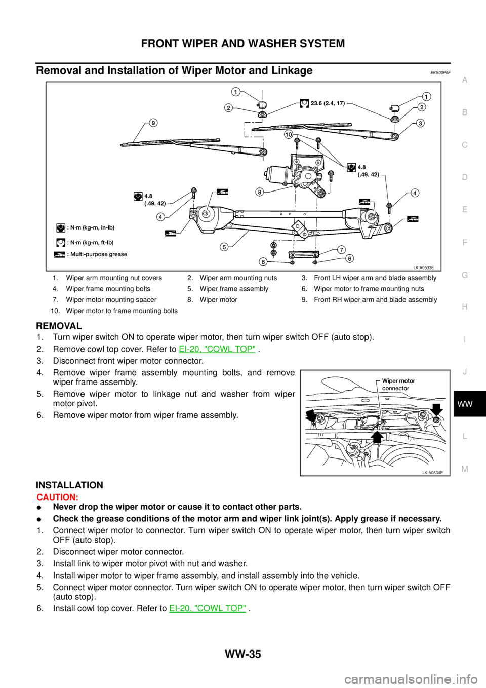
1. Wiper arm mounting nut covers 2. Wiper arm mounting nuts 3. Front LH wiper arm and blade assembly
4. Wiper frame mounting bolts 5. Wiper frame assembly 6. Wiper motor to frame mounting nuts
7. Wiper motor mounting spacer 8. Wiper motor 9. Front RH wiper arm and blade assembly
10. Wiper motor to frame mounting bolts
LKIA0533E
LKIA0534E
Page 3147 of 3171
WW-36
FRONT WIPER AND WASHER SYSTEM
Washer Nozzle Adjustment
EKS00P5G
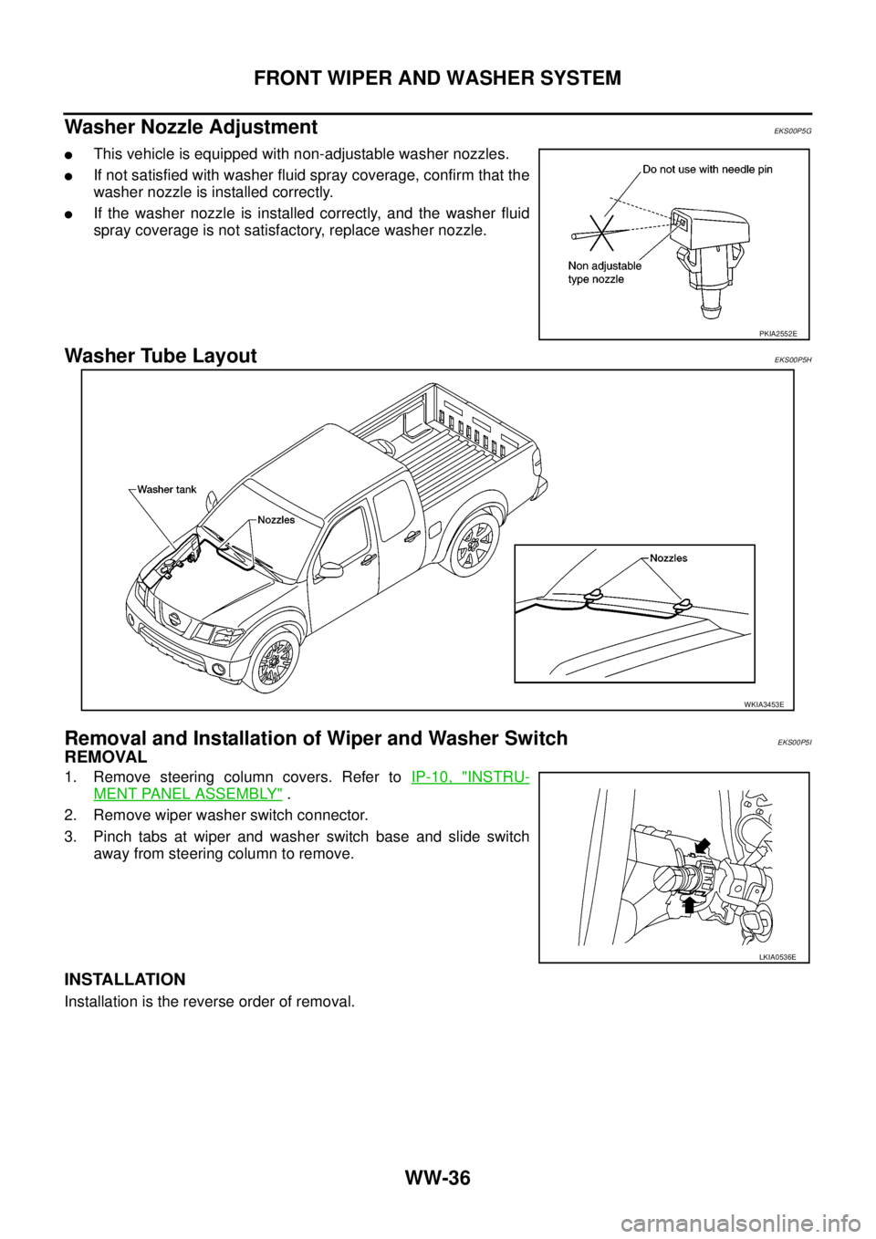
lThis vehicle is equipped with non-adjustable washer nozzles.
lIf not satisfied with washer fluid spray coverage, confirm that the
washer nozzle is installed correctly.
lIf the washer nozzle is installed correctly, and the washer fluid
spray coverage is not satisfactory, replace washer nozzle.
Washer Tube LayoutEKS00P5H
Removal and Installation of Wiper and Washer SwitchEKS00P5I
REMOVAL
1. Remove steering column covers. Refer toIP-10, "INSTRU-
MENT PANEL ASSEMBLY".
2. Remove wiper washer switch connector.
3. Pinch tabs at wiper and washer switch base and slide switch
away from steering column to remove.
INSTALLATION
Installation is the reverse order of removal.
PKIA2552E
WKIA3453E
LKIA0536E
Page 3148 of 3171

FRONT WIPER AND WASHER SYSTEM
WW-37
C
D
E
F
G
H
I
J
L
MA
B
WW
Removal and Installation of Front Washer TankEKS00P5J
REMOVAL
1. Remove front fender protector. Refer toEI-22, "Removal and Installation of Front Fender Protector".
2. Remove front washer hoses from washer motor (A) and
headlamp washer hose from headlamp washer motor (B); allow
washer fluid to drain.
3. Disconnect front washer motor (A) connector, headlamp washer
motor (B) connector and washer fluid level sensor (C) connec-
tor.
4. Remove clip, then remove washer tank filler neck from washer
tank.
5. Remove washer tank screws and remove washer tank.
INSTALLATION
CAUTION:
After installation, add water up to the upper level of the washer tank inlet, and check for water leaks.
Installation is the reverse order of removal.
SKIB6854E
LKIA0538E
LKIA0539E
Washer tank mounting screws : 5.5 N·m (0.56 kg-m, 49 in-lb)
Page 3149 of 3171

WW-38
FRONT WIPER AND WASHER SYSTEM
Removal and Installation of Front Washer Motor
EKS00P5K
REMOVAL
: Vehicle front
1. Remove washer tank. Refer toWW-37, "
Removal and Installation of Front Washer Tank".
2. Pull out front washer motor (1) and remove from washer tank.
INSTALLATION
Installation is the reverse order of removal.
CAUTION:
When installing front washer motor, there should be no packing twist, etc.
Removal and Installation of Washer Fluid Level SensorEKS00P5L
REMOVAL
: Vehicle front
1. Remove washer tank. Refer toWW-37, "
Removal and Installation of Front Washer Tank".
2. Pull out washer fluid level sensor (1) and remove from washer
tank in the direction of the arrow as shown.
INSTALLATION
Installation is the reverse order of removal.
CAUTION:
When installing washer fluid level sensor, there should be no packing twist, etc.
SKIB6855E
SKIB6856E
Page 3150 of 3171
HEADLAMP WASHER
WW-39
C
D
E
F
G
H
I
J
L
MA
B
WW
HEADLAMP WASHERPFP:28620
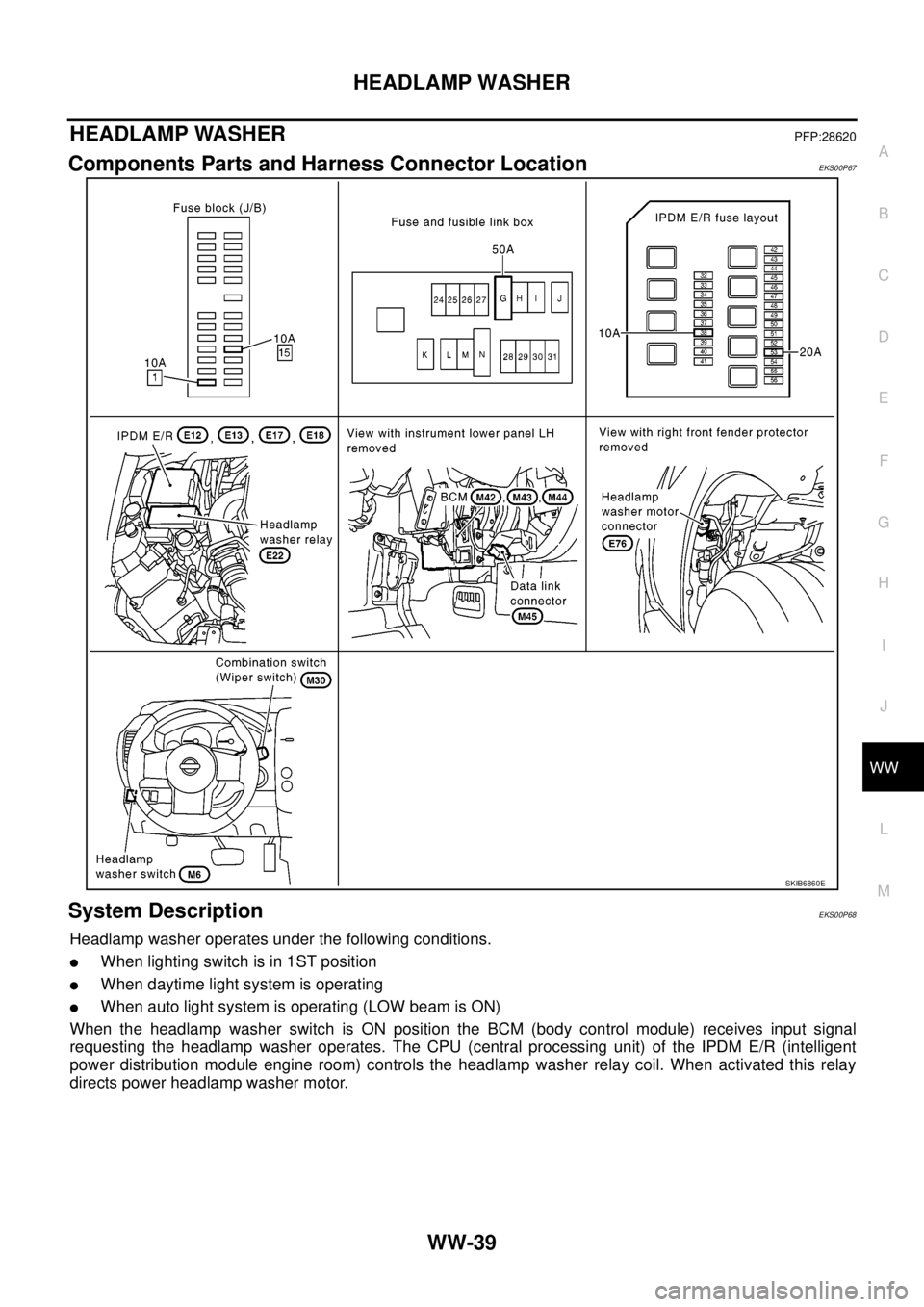
Components Parts and Harness Connector LocationEKS00P67
System DescriptionEKS00P68
Headlamp washer operates under the following conditions.
lWhen lighting switch is in 1ST position
lWhen daytime light system is operating
lWhen auto light system is operating (LOW beam is ON)
When the headlamp washer switch is ON position the BCM (body control module) receives input signal
requesting the headlamp washer operates. The CPU (central processing unit) of the IPDM E/R (intelligent
power distribution module engine room) controls the headlamp washer relay coil. When activated this relay
directs power headlamp washer motor.
SKIB6860E