NISSAN NAVARA 2005 Repair Workshop Manual
Manufacturer: NISSAN, Model Year: 2005, Model line: NAVARA, Model: NISSAN NAVARA 2005Pages: 3171, PDF Size: 49.59 MB
Page 3101 of 3171
TF-134
FRONT DRIVE SHAFT
ASSEMBLY
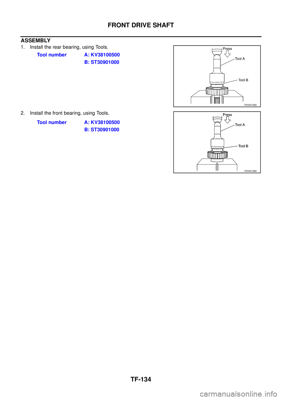
1. Install the rear bearing, using Tools.
2. Install the front bearing, using Tools.Tool number A: KV38100500
B: ST30901000
PDIA0155E
Tool number A: KV38100500
B: ST30901000
PDIA0156E
Page 3102 of 3171
SHIFT CONTROL
TF-135
C
E
F
G
H
I
J
K
L
MA
B
TF
SHIFT CONTROLPFP:33167
Disassembly and AssemblyEDS0032S
DISASSEMBLY (A/T MODELS)
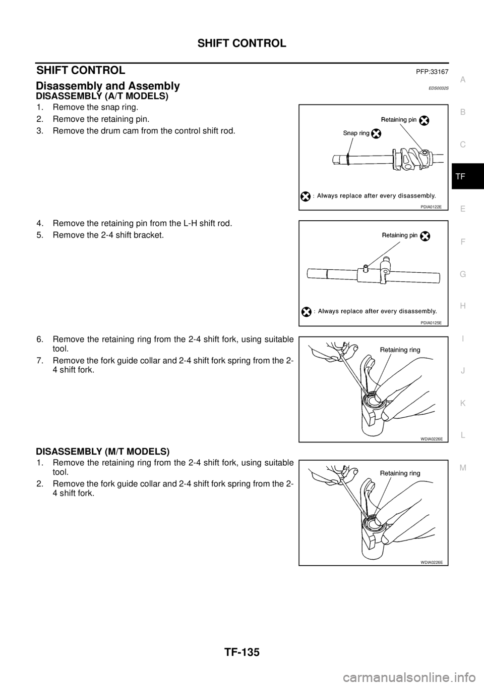
1. Remove the snap ring.
2. Remove the retaining pin.
3. Remove the drum cam from the control shift rod.
4. Remove the retaining pin from the L-H shift rod.
5. Remove the 2-4 shift bracket.
6. Remove the retaining ring from the 2-4 shift fork, using suitable
tool.
7. Remove the fork guide collar and 2-4 shift fork spring from the 2-
4 shift fork.
DISASSEMBLY (M/T MODELS)
1. Remove the retaining ring from the 2-4 shift fork, using suitable
tool.
2. Remove the fork guide collar and 2-4 shift fork spring from the 2-
4 shift fork.
PDIA0122E
PDIA0125E
WDIA0226E
WDIA0226E
Page 3103 of 3171
TF-136
SHIFT CONTROL
INSPECTION AFTER DISASSEMBLY
Shift Fork
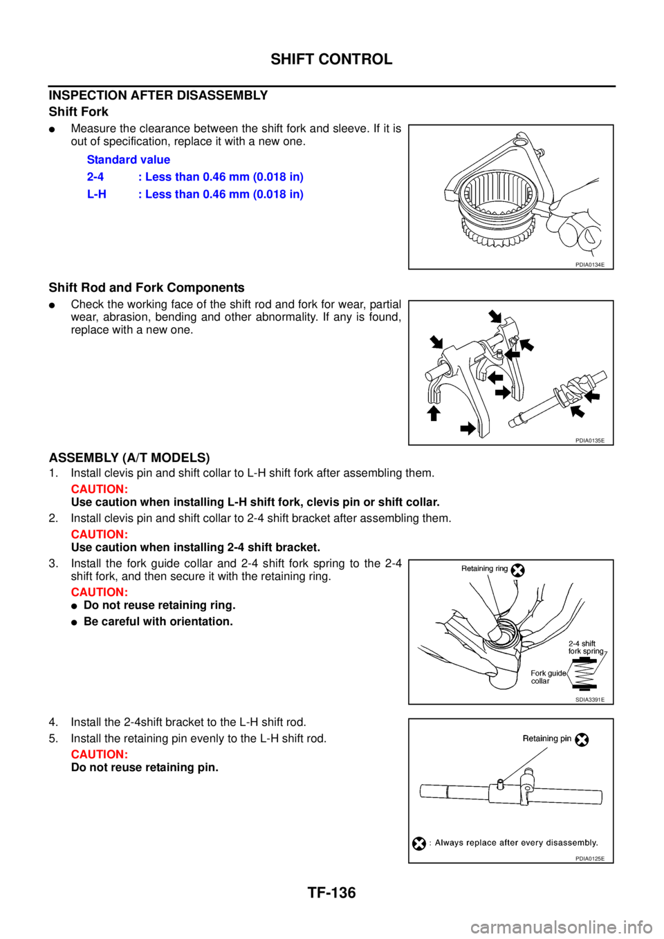
lMeasure the clearance between the shift fork and sleeve. If it is
out of specification, replace it with a new one.
Shift Rod and Fork Components
lCheck the working face of the shift rod and fork for wear, partial
wear, abrasion, bending and other abnormality. If any is found,
replace with a new one.
ASSEMBLY (A/T MODELS)
1. Install clevis pin and shift collar to L-H shift fork after assembling them.
CAUTION:
Use caution when installing L-H shift fork, clevis pin or shift collar.
2. Install clevis pin and shift collar to 2-4 shift bracket after assembling them.
CAUTION:
Use caution when installing 2-4 shift bracket.
3. Install the fork guide collar and 2-4 shift fork spring to the 2-4
shift fork, and then secure it with the retaining ring.
CAUTION:
lDo not reuse retaining ring.
lBe careful with orientation.
4. Install the 2-4shift bracket to the L-H shift rod.
5. Install the retaining pin evenly to the L-H shift rod.
CAUTION:
Do not reuse retaining pin.Standard value
2-4 : Less than 0.46 mm (0.018 in)
L-H : Less than 0.46 mm (0.018 in)
PDIA0134E
PDIA0135E
SDIA3391E
PDIA0125E
Page 3104 of 3171
SHIFT CONTROL
TF-137
C
E
F
G
H
I
J
K
L
MA
B
TF
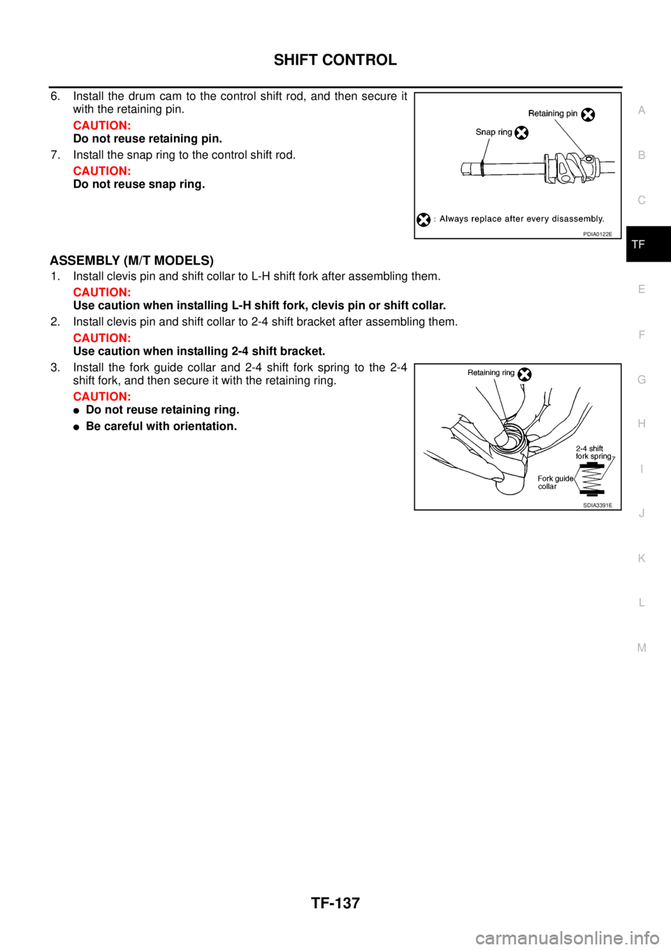
6. Install the drum cam to the control shift rod, and then secure it
with the retaining pin.
CAUTION:
Do not reuse retaining pin.
7. Install the snap ring to the control shift rod.
CAUTION:
Do not reuse snap ring.
ASSEMBLY (M/T MODELS)
1. Install clevis pin and shift collar to L-H shift fork after assembling them.
CAUTION:
Use caution when installing L-H shift fork, clevis pin or shift collar.
2. Install clevis pin and shift collar to 2-4 shift bracket after assembling them.
CAUTION:
Use caution when installing 2-4 shift bracket.
3. Install the fork guide collar and 2-4 shift fork spring to the 2-4
shift fork, and then secure it with the retaining ring.
CAUTION:
lDo not reuse retaining ring.
lBe careful with orientation.
PDIA0122E
SDIA3391E
Page 3105 of 3171

TF-138
SERVICE DATA AND SPECIFICATIONS (SDS)
SERVICE DATA AND SPECIFICATIONS (SDS)
PFP:00030
General SpecificationsEDS0032T
Inspection and AdjustmentEDS0032U
PINION GEAR END PLAY
Unit: mm (in)
CLEARANCE BETWEEN SHIFT FORK AND SLEEVE
Unit: mm (in) Applied modelYD25DDTi
Transfer modelTX15B
Fluid capacity (Approx.)
(lmp qt)2.0 (1-3/4)
Gear ratioHigh 1.000
Low 2.625
Number of teethPlanetary
gearSun gear 56
Internal gear 91
Front drive sprocket 38
Front drive shaft 38
Item Standard
Pinion gear end play 0.1 - 0.7 (0.004 - 0.028)
Item Standard
2-4 shift fork to 2-4 sleeve Less than 0.46 (0.018)
L-H shift fork to L-H sleeve Less than 0.46 (0.018)
Page 3106 of 3171

WT-1
ROAD WHEELS & TIRES
E SUSPENSION
CONTENTS
C
D
F
G
H
I
J
K
L
M
SECTIONWT
A
B
WT
ROAD WHEELS & TIRES
NOISE, VIBRATION, AND HARSHNESS (NVH)
TROUBLESHOOTING ................................................ 2
NVH Troubleshooting Chart ..................................... 2
WHEEL ....................................................................... 3
Inspection ................................................................. 3
STEEL WHEEL ..................................................... 3
WHEEL AND TIRE ASSEMBLY ................................. 4Balancing Wheels ..................................................... 4
REMOVAL ............................................................. 4
WHEEL BALANCE ADJUSTMENT ....................... 4
Rotation .................................................................... 5
SERVICE DATA AND SPECIFICATIONS (SDS) ........ 6
Road Wheel .............................................................. 6
Tire ........................................................................... 6
Page 3107 of 3171

WT-2
NOISE, VIBRATION, AND HARSHNESS (NVH) TROUBLESHOOTING
NOISE, VIBRATION, AND HARSHNESS (NVH) TROUBLESHOOTING
PFP:00003
NVH Troubleshooting ChartEES002L1
Use chart below to help you find the cause of the symptom. If necessary, repair or replace these parts.
´: ApplicableReference page
WT-3WT-4WT-6WT-4—
—
WT-6
FFD-6
(FFD)
RFD-XX “NVH Troubleshooting Chart” (RFD, M226 without LD),
RFD-XX “NVH Troubleshooting Chart” (RFD, M226 with LD)
FAX-4(FAX)
FSU-5(FSU)
RAX-5(RAX)
RSU-3(RSU)
Refer to TIRES in this chart.
Refer to ROAD WHEEL in this chart.
BR-5
PS-5
Possible cause and SUSPECTED PARTS
Out-of-round
Imbalance
Incorrect tire pressure
Uneven tire wear
Deformation or damage
Non-uniformity
Incorrect tire size
FRONT AND REAR FINAL DRIVE
FRONT AXLE AND FRONT SUSPENSION
REAR AXLE AND REAR SUSPENSION
TIRES
ROAD WHEEL
BRAKE
STEERING
SymptomTIRESNoise´ ´´´´´ ´ ´ ´ ´ ´ ´
Shake´´´´´ ´ ´ ´ ´ ´´
Vibration´´´´´´
Shimmy´ ´´´´´´ ´ ´ ´ ´ ´
Shudder´´´´´ ´ ´ ´ ´ ´´
Poor quality ride or
handling´´´´´ ´ ´ ´ ´
ROAD
WHEELNoise´´ ´ ´ ´ ´ ´´´
Shake´´ ´ ´ ´ ´´´
Shimmy, shudder´´ ´ ´ ´ ´´´
Poor quality ride or
handling´´ ´ ´ ´ ´
Page 3108 of 3171
WHEEL
WT-3
C
D
F
G
H
I
J
K
L
MA
B
WT
WHEELPFP:40300
InspectionEES002L2
1. Check tires for wear and improper inflation.
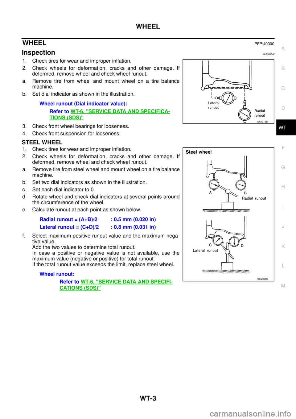
2. Check wheels for deformation, cracks and other damage. If
deformed, remove wheel and check wheel runout.
a. Remove tire from wheel and mount wheel on a tire balance
machine.
b. Set dial indicator as shown in the illustration.
3. Check front wheel bearings for looseness.
4. Check front suspension for looseness.
STEEL WHEEL
1. Check tires for wear and improper inflation.
2. Check wheels for deformation, cracks and other damage. If
deformed, remove wheel and check wheel runout.
a. Remove tire from steel wheel and mount wheel on a tire balance
machine.
b. Set two dial indicators as shown in the illustration.
c. Set each dial indicator to 0.
d. Rotate wheel and check dial indicators at several points around
the circumference of the wheel.
e. Calculate runout at each point as shown below.
f. Select maximum positive runout value and the maximum nega-
tive value.
Add the two values to determine total runout.
In case a positive or negative value is not available, use the
maximum value (negative or positive) for total runout.
If the total runout value exceeds the limit, replace steel wheel.Wheel runout (Dial indicator value):
Refer toWT-6, "
SERVICE DATA AND SPECIFICA-
TIONS (SDS)"SFA975B
Radial runout = (A+B)/2 : 0.5 mm (0.020 in)
Lateral runout = (C+D)/2 : 0.8 mm (0.031 in)
Wheel runout:
Refer toWT-6, "
SERVICE DATA AND SPECIFI-
CATIONS (SDS)"
SFA981B
Page 3109 of 3171
WT-4
WHEEL AND TIRE ASSEMBLY
WHEEL AND TIRE ASSEMBLY
PFP:40300
Balancing WheelsEES002L3
REMOVAL
1. Using releasing agent, remove double-faced adhesive tape from the wheel.
CAUTION:
lBe careful not to scratch the wheel during removal.
lAfter removing double-faced adhesive tape, wipe clean traces of releasing agent from the
wheel.
WHEEL BALANCE ADJUSTMENT
lIf a tire balance machine has adhesion balance weight mode settings and drive-in weight mode setting,
select and adjust a drive-in weight mode suitable for wheels.
1. Set wheel on wheel balancer using the center hole as a guide. Start the tire balance machine.
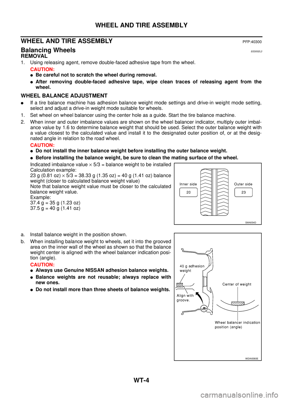
2. When inner and outer imbalance values are shown on the wheel balancer indicator, multiply outer imbal-
ance value by 1.6 to determine balance weight that should be used. Select the outer balance weight with
a value closest to the calculated value and install it to the designated outer position of, or at the desig-
nated angle in relation to the road wheel.
CAUTION:
lDo not install the inner balance weight before installing the outer balance weight.
lBefore installing the balance weight, be sure to clean the mating surface of the wheel.
Indicated imbalance value´5/3 = balance weight to be installed
Calculation example:
23 g (0.81 oz)´5/3 = 38.33 g (1.35 oz) = 40 g (1.41 oz) balance
weight (closer to calculated balance weight value)
Note that balance weight value must be closer to the calculated
balance weight value.
Example:
37.4 g = 35 g (1.23 oz)
37.5 g = 40 g (1.41 oz)
a. Install balance weight in the position shown.
b. When installing balance weight to wheels, set it into the grooved
area on the inner wall of the wheel as shown so that the balance
weight center is aligned with the wheel balancer indication posi-
tion (angle).
CAUTION:
lAlways use Genuine NISSAN adhesion balance weights.
lBalance weights are not reusable; always replace with
new ones.
lDo not install more than three sheets of balance weights.
SMA054D
WDIA0060E
Page 3110 of 3171
WHEEL AND TIRE ASSEMBLY
WT-5
C
D
F
G
H
I
J
K
L
MA
B
WT
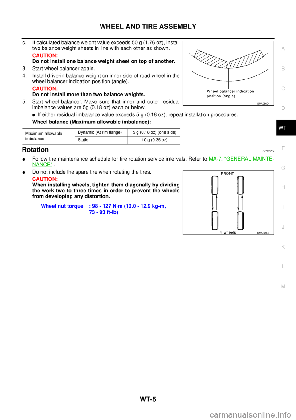
c. If calculated balance weight value exceeds 50 g (1.76 oz), install
two balance weight sheets in line with each other as shown.
CAUTION:
Do not install one balance weight sheet on top of another.
3. Start wheel balancer again.
4. Install drive-in balance weight on inner side of road wheel in the
wheel balancer indication position (angle).
CAUTION:
Do not install more than two balance weights.
5. Start wheel balancer. Make sure that inner and outer residual
imbalance values are 5g (0.18 oz) each or below.
lIf either residual imbalance value exceeds 5 g (0.18 oz), repeat installation procedures.
Wheel balance (Maximum allowable imbalance):
RotationEES002L4
lFollow the maintenance schedule for tire rotation service intervals. Refer toMA-7, "GENERAL MAINTE-
NANCE".
lDo not include the spare tire when rotating the tires.
CAUTION:
When installing wheels, tighten them diagonally by dividing
the work two to three times in order to prevent the wheels
from developing any distortion.
Maximum allowable
imbalanceDynamic (At rim flange) 5 g (0.18 oz) (one side)
Static 10 g (0.35 oz)
SMA056D
Wheel nut torque : 98 - 127 N·m (10.0 - 12.9 kg-m,
73 - 93 ft-lb)
SMA829C