NISSAN NAVARA 2005 Repair Workshop Manual
NAVARA 2005
NISSAN
NISSAN
https://www.carmanualsonline.info/img/5/57362/w960_57362-0.png
NISSAN NAVARA 2005 Repair Workshop Manual
Trending: water pump, turn signal, steering wheel, coolant temperature, air filter, tow, key
Page 3161 of 3171
WW-50
HEADLAMP WASHER
Headlamp Washer Does Not Operate
EKS00P6G
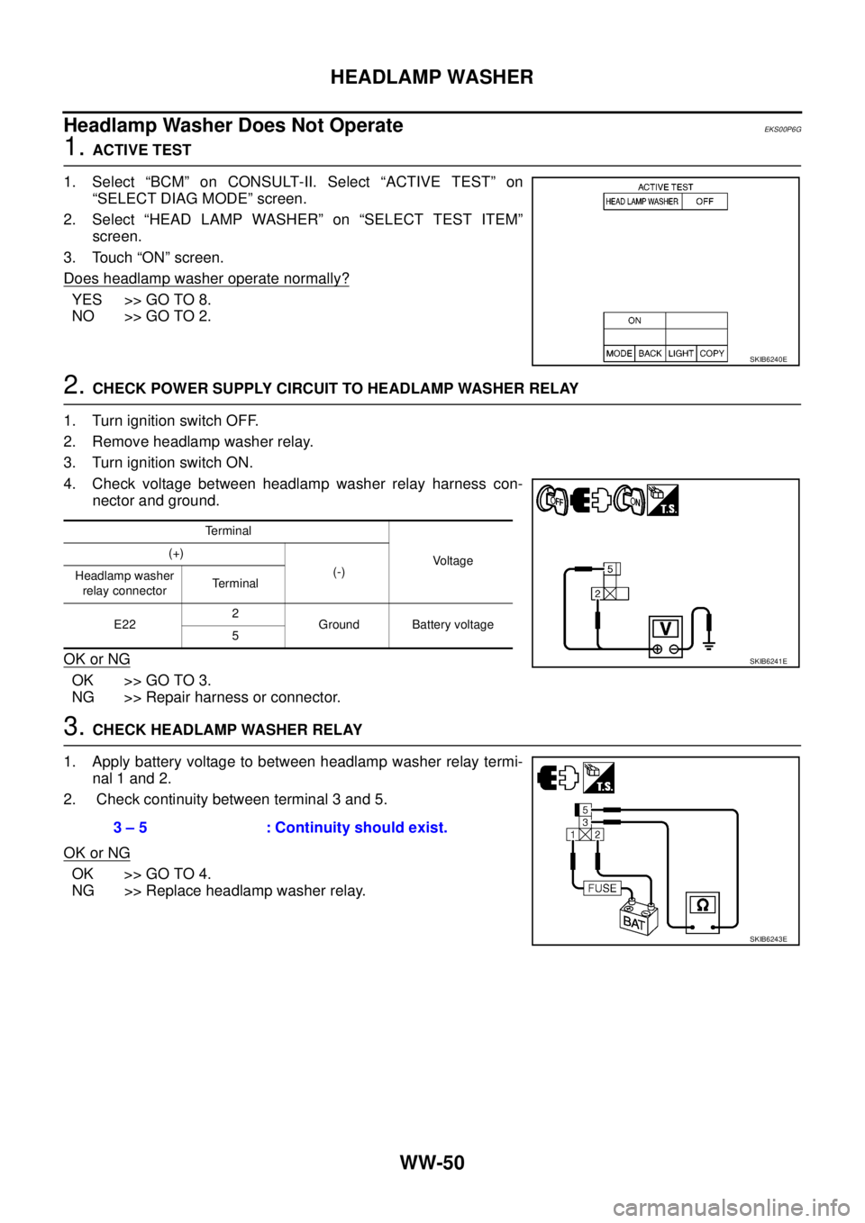
1.ACTIVE TEST
1. Select “BCM” on CONSULT-II. Select “ACTIVE TEST” on
“SELECT DIAG MODE” screen.
2. Select “HEAD LAMP WASHER” on “SELECT TEST ITEM”
screen.
3. Touch “ON” screen.
Does headlamp washer operate normally?
YES >> GO TO 8.
NO >> GO TO 2.
2.CHECK POWER SUPPLY CIRCUIT TO HEADLAMP WASHER RELAY
1. Turn ignition switch OFF.
2. Remove headlamp washer relay.
3. Turn ignition switch ON.
4. Check voltage between headlamp washer relay harness con-
nector and ground.
OK or NG
OK >> GO TO 3.
NG >> Repair harness or connector.
3.CHECK HEADLAMP WASHER RELAY
1. Apply battery voltage to between headlamp washer relay termi-
nal 1 and 2.
2. Check continuity between terminal 3 and 5.
OK or NG
OK >> GO TO 4.
NG >> Replace headlamp washer relay.
SKIB6240E
Terminal
Voltage (+)
(-)
Headlamp washer
relay connectorTerminal
E222
Ground Battery voltage
5
SKIB6241E
3 – 5 : Continuity should exist.
SKIB6243E
Page 3162 of 3171
HEADLAMP WASHER
WW-51
C
D
E
F
G
H
I
J
L
MA
B
WW
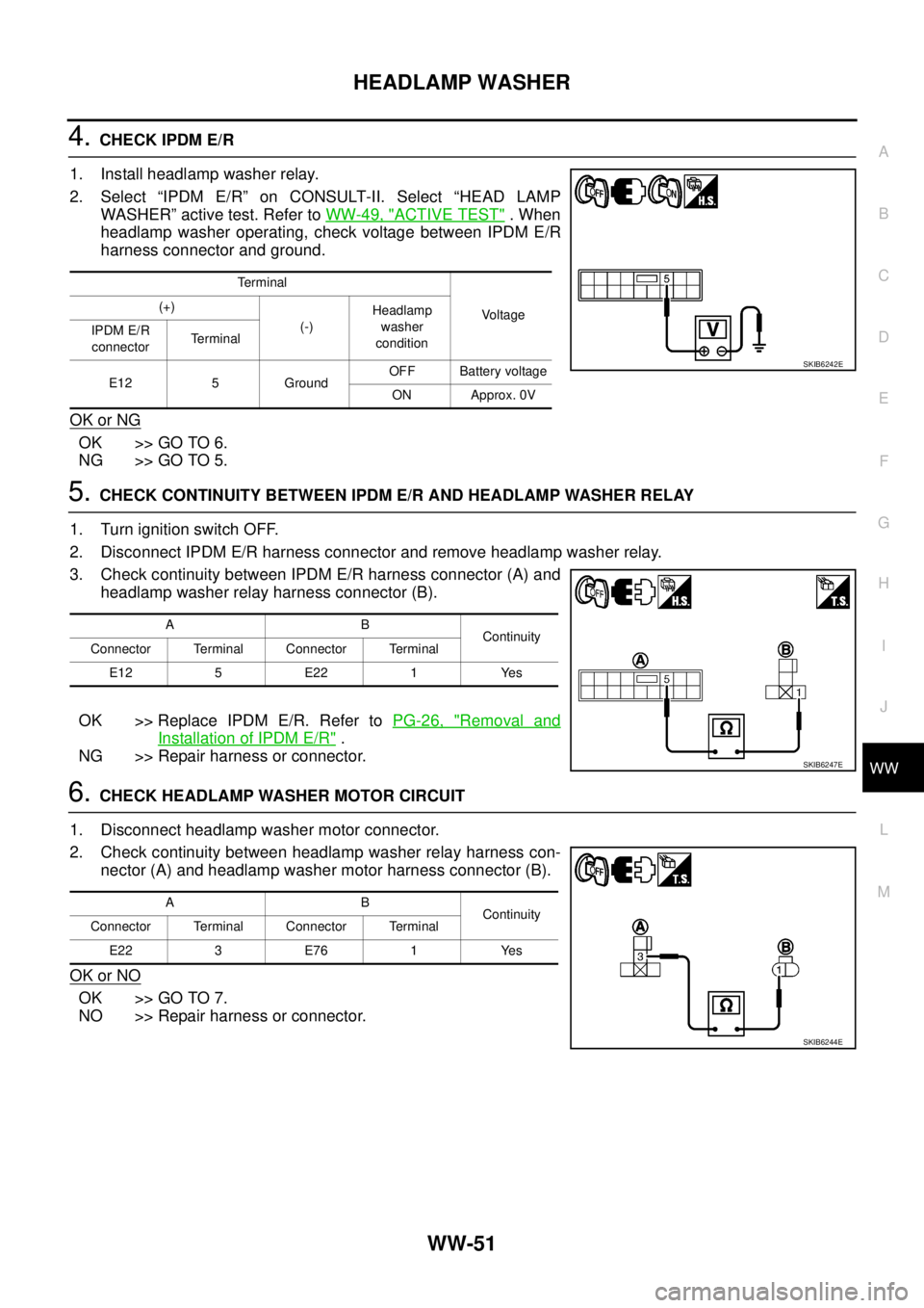
4.CHECK IPDM E/R
1. Install headlamp washer relay.
2. Select “IPDM E/R” on CONSULT-II. Select “HEAD LAMP
WASHER” active test. Refer toWW-49, "
ACTIVE TEST".When
headlamp washer operating, check voltage between IPDM E/R
harness connector and ground.
OK or NG
OK >> GO TO 6.
NG >> GO TO 5.
5.CHECK CONTINUITY BETWEEN IPDM E/R AND HEADLAMP WASHER RELAY
1. Turn ignition switch OFF.
2. Disconnect IPDM E/R harness connector and remove headlamp washer relay.
3. Check continuity between IPDM E/R harness connector (A) and
headlamp washer relay harness connector (B).
OK >> Replace IPDM E/R. Refer toPG-26, "
Removal and
Installation of IPDM E/R".
NG >> Repair harness or connector.
6.CHECK HEADLAMP WASHER MOTOR CIRCUIT
1. Disconnect headlamp washer motor connector.
2. Check continuity between headlamp washer relay harness con-
nector (A) and headlamp washer motor harness connector (B).
OK or NO
OK >> GO TO 7.
NO >> Repair harness or connector.
Terminal
Vo l ta g e (+)
(-)Headlamp
washer
condition IPDM E/R
connectorTerminal
E12 5 GroundOFF Battery voltage
ON Approx. 0V
SKIB6242E
AB
Continuity
Connector Terminal Connector Terminal
E12 5 E22 1 Yes
SKIB6247E
AB
Continuity
Connector Terminal Connector Terminal
E22 3 E76 1 Yes
SKIB6244E
Page 3163 of 3171
WW-52
HEADLAMP WASHER
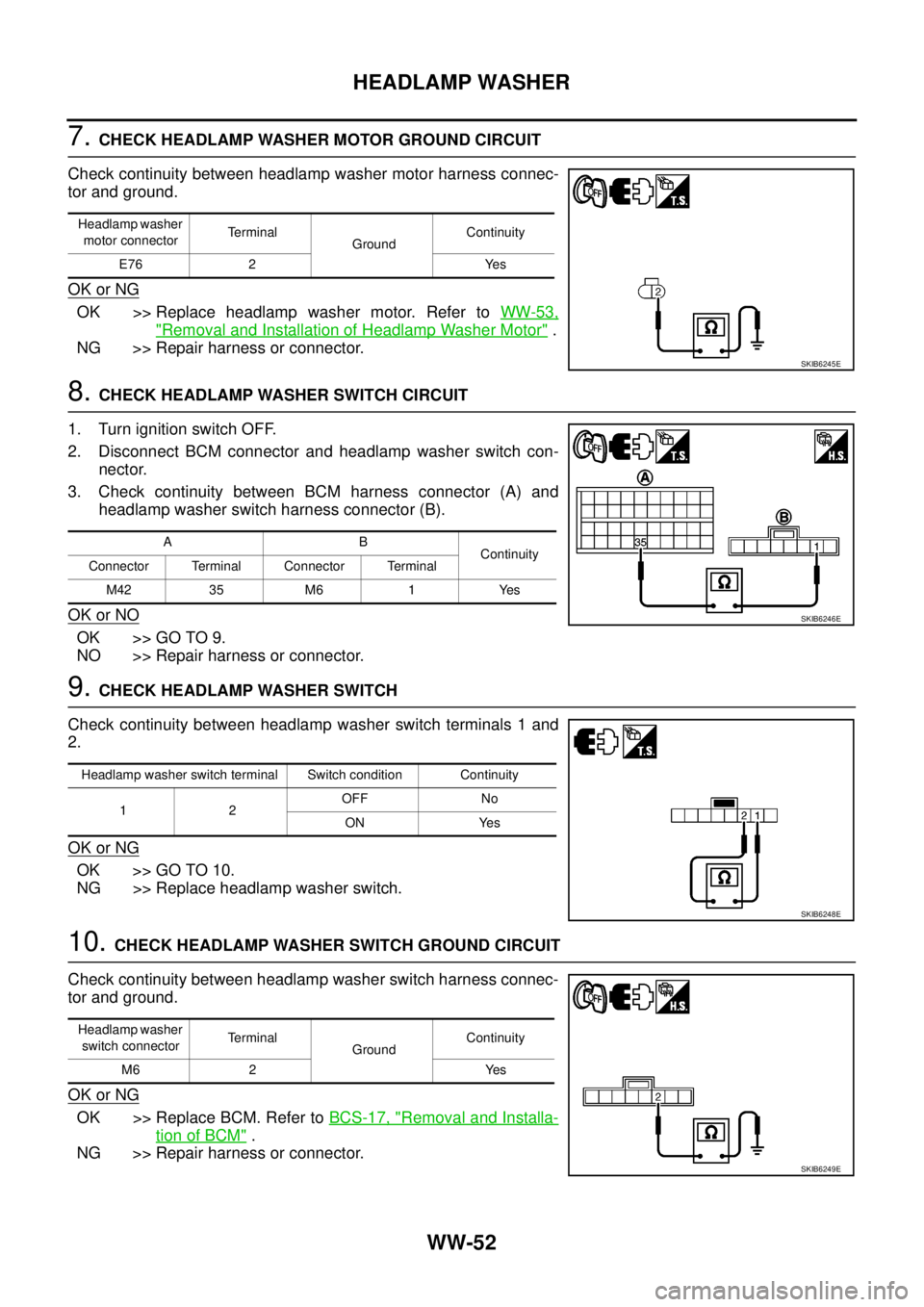
7.CHECK HEADLAMP WASHER MOTOR GROUND CIRCUIT
Check continuity between headlamp washer motor harness connec-
tor and ground.
OK or NG
OK >> Replace headlamp washer motor. Refer toWW-53,
"Removal and Installation of Headlamp Washer Motor".
NG >> Repair harness or connector.
8.CHECK HEADLAMP WASHER SWITCH CIRCUIT
1. Turn ignition switch OFF.
2. Disconnect BCM connector and headlamp washer switch con-
nector.
3. Check continuity between BCM harness connector (A) and
headlamp washer switch harness connector (B).
OK or NO
OK >> GO TO 9.
NO >> Repair harness or connector.
9.CHECK HEADLAMP WASHER SWITCH
Check continuity between headlamp washer switch terminals 1 and
2.
OK or NG
OK >> GO TO 10.
NG >> Replace headlamp washer switch.
10.CHECK HEADLAMP WASHER SWITCH GROUND CIRCUIT
Check continuity between headlamp washer switch harness connec-
tor and ground.
OK or NG
OK >> Replace BCM. Refer toBCS-17, "Removal and Installa-
tion of BCM".
NG >> Repair harness or connector.
Headlamp washer
motor connectorTerminal
GroundContinuity
E76 2 Yes
SKIB6245E
AB
Continuity
Connector Terminal Connector Terminal
M42 35 M6 1 Yes
SKIB6246E
Headlamp washer switch terminal Switch condition Continuity
12OFF No
ON Yes
SKIB6248E
Headlamp washer
switch connectorTerminal
GroundContinuity
M6 2 Yes
SKIB6249E
Page 3164 of 3171
HEADLAMP WASHER
WW-53
C
D
E
F
G
H
I
J
L
MA
B
WW
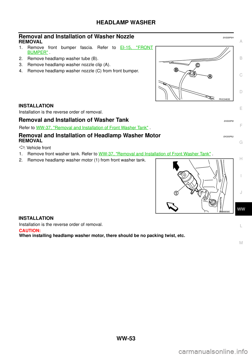
Removal and Installation of Washer NozzleEKS00P6H
REMOVAL
1. Remove front bumper fascia. Refer toEI-15, "FRONT
BUMPER".
2. Remove headlamp washer tube (B).
3. Remove headlamp washer nozzle clip (A).
4. Remove headlamp washer nozzle (C) from front bumper.
INSTALLATION
Installation is the reverse order of removal.
Removal and Installation of Washer TankEKS00P6I
Refer toWW-37, "Removal and Installation of Front Washer Tank".
Removal and Installation of Headlamp Washer MotorEKS00P6J
REMOVAL
: Vehicle front
1. Remove front washer tank. Refer toWW-37, "
Removal and Installation of Front Washer Tank".
2. Remove headlamp washer motor (1) from front washer tank.
INSTALLATION
Installation is the reverse order of removal.
CAUTION:
When installing headlamp washer motor, there should be no packing twist, etc.
PKIC0463E
SKIB6858E
Page 3165 of 3171
WW-54
HEADLAMP WASHER
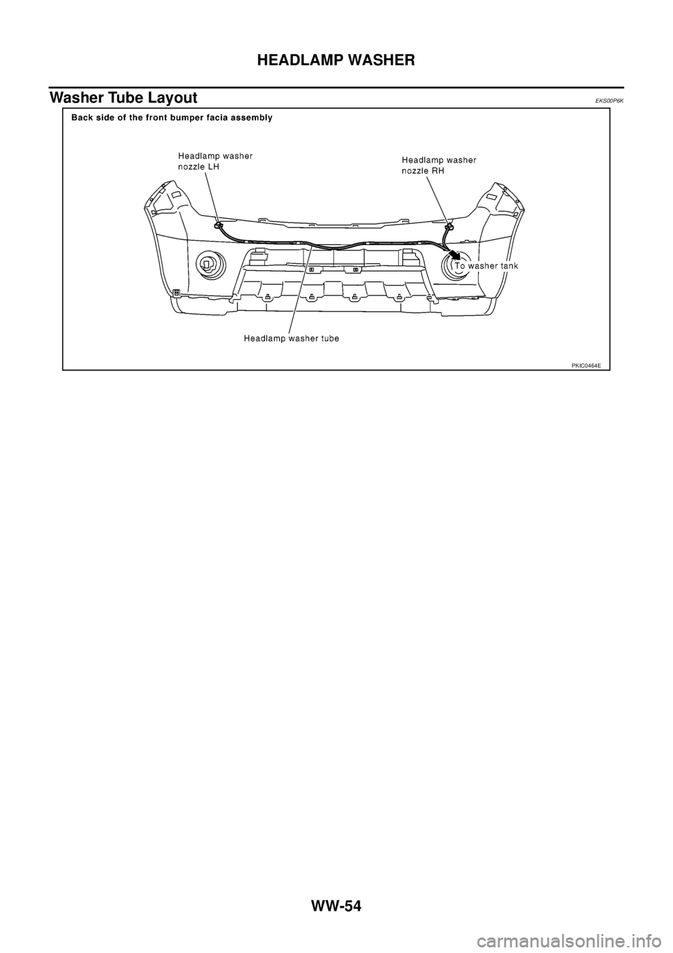
Washer Tube Layout
EKS00P6K
PKIC0464E
Page 3166 of 3171
CIGARETTE LIGHTER
WW-55
C
D
E
F
G
H
I
J
L
MA
B
WW
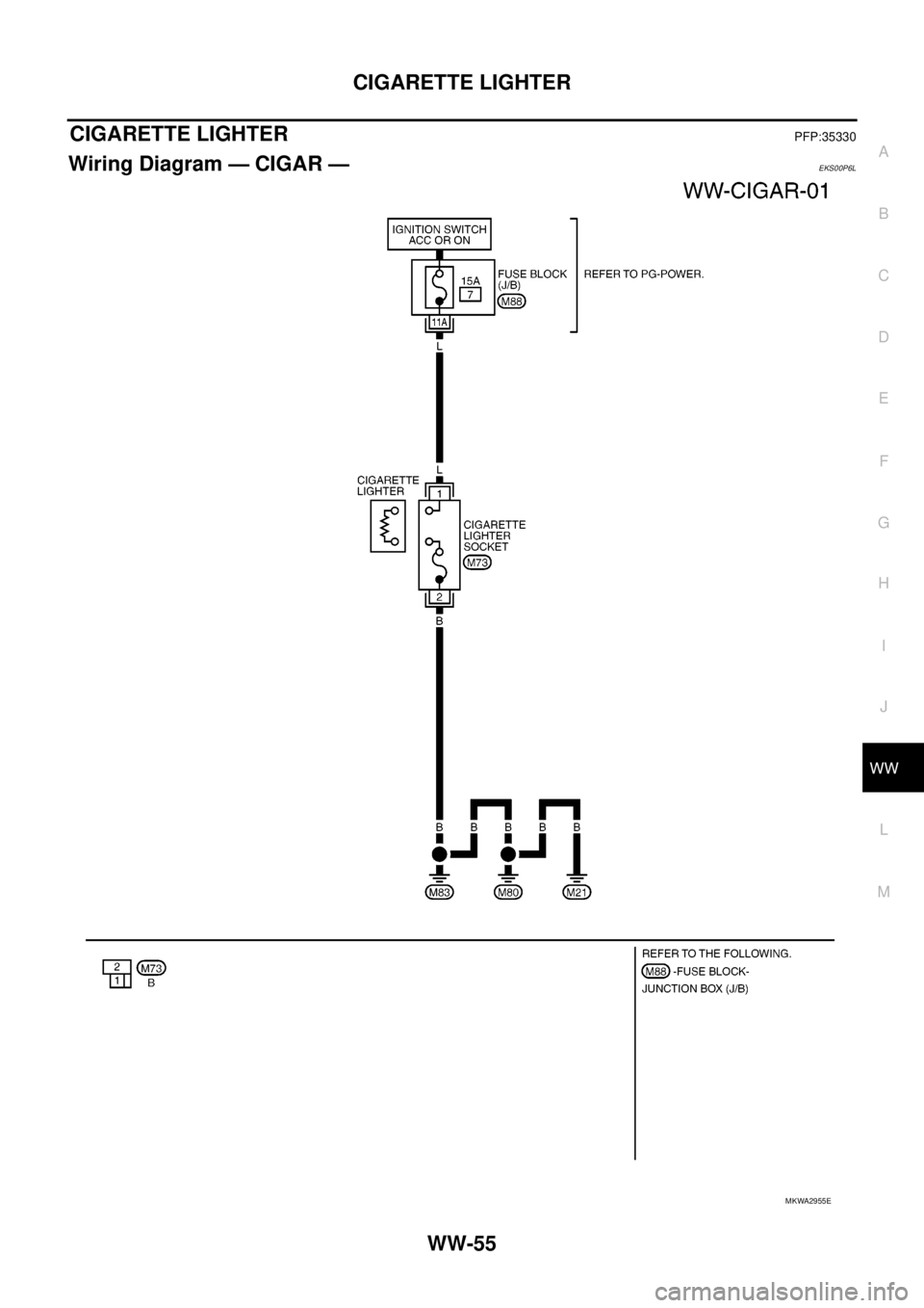
CIGARETTE LIGHTERPFP:35330
Wiring Diagram — CIGAR —EKS00P6L
MKWA2955E
Page 3167 of 3171
WW-56
CIGARETTE LIGHTER
Removal and Installation of Cigarette Lighter
EKS00P6M
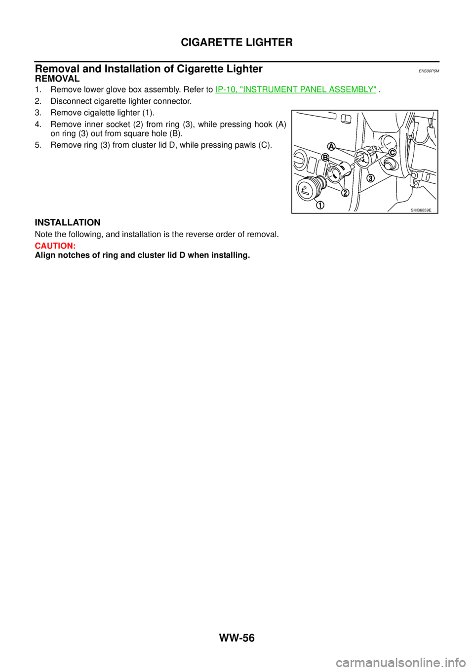
REMOVAL
1. Remove lower glove box assembly. Refer toIP-10, "INSTRUMENT PANEL ASSEMBLY".
2. Disconnect cigarette lighter connector.
3. Remove cigalette lighter (1).
4. Remove inner socket (2) from ring (3), while pressing hook (A)
on ring (3) out from square hole (B).
5. Remove ring (3) from cluster lid D, while pressing pawls (C).
INSTALLATION
Note the following, and installation is the reverse order of removal.
CAUTION:
Align notches of ring and cluster lid D when installing.
SKIB6859E
Page 3168 of 3171
POWER SOCKET
WW-57
C
D
E
F
G
H
I
J
L
MA
B
WW
POWER SOCKETPFP:253A2
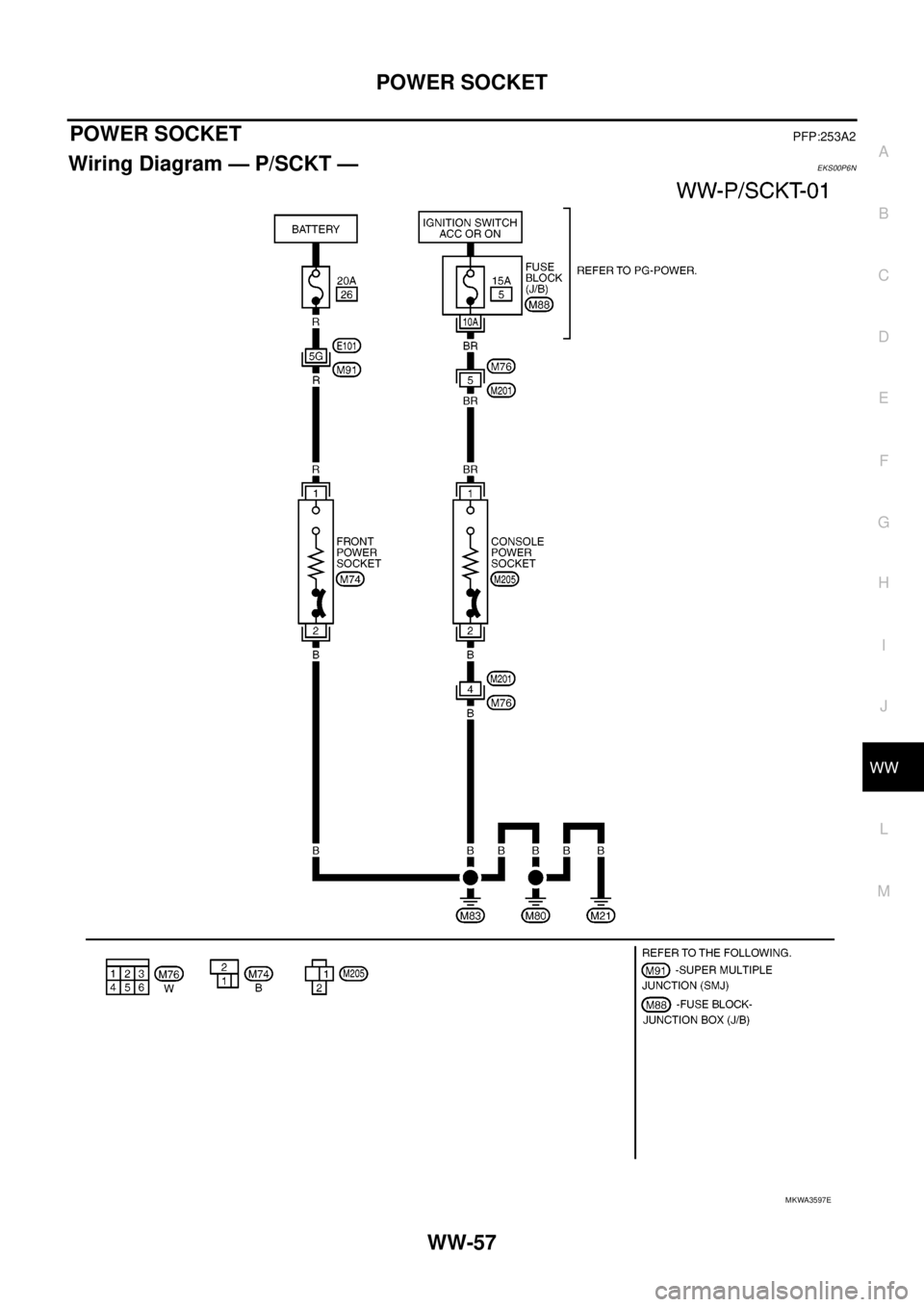
Wiring Diagram — P/SCKT —EKS00P6N
MKWA3597E
Page 3169 of 3171
WW-58
POWER SOCKET
Removal and Installation of Front Power Socket
EKS00P6O
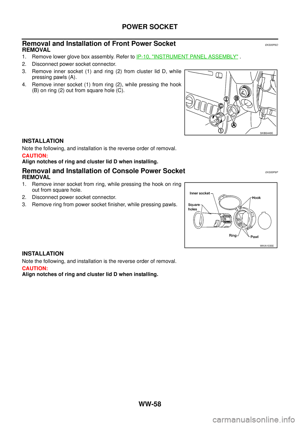
REMOVAL
1. Remove lower glove box assembly. Refer toIP-10, "INSTRUMENT PANEL ASSEMBLY".
2. Disconnect power socket connector.
3. Remove inner socket (1) and ring (2) from cluster lid D, while
pressing pawls (A).
4. Remove inner socket (1) from ring (2), while pressing the hook
(B) on ring (2) out from square hole (C).
INSTALLATION
Note the following, and installation is the reverse order of removal.
CAUTION:
Align notches of ring and cluster lid D when installing.
Removal and Installation of Console Power SocketEKS00P6P
REMOVAL
1. Remove inner socket from ring, while pressing the hook on ring
out from square hole.
2. Disconnect power socket connector.
3. Remove ring from power socket finisher, while pressing pawls.
INSTALLATION
Note the following, and installation is the reverse order of removal.
CAUTION:
Align notches of ring and cluster lid D when installing.
SKIB6448E
WKIA1035E
Page 3170 of 3171
HORN
WW-59
C
D
E
F
G
H
I
J
L
MA
B
WW
HORNPFP:25610
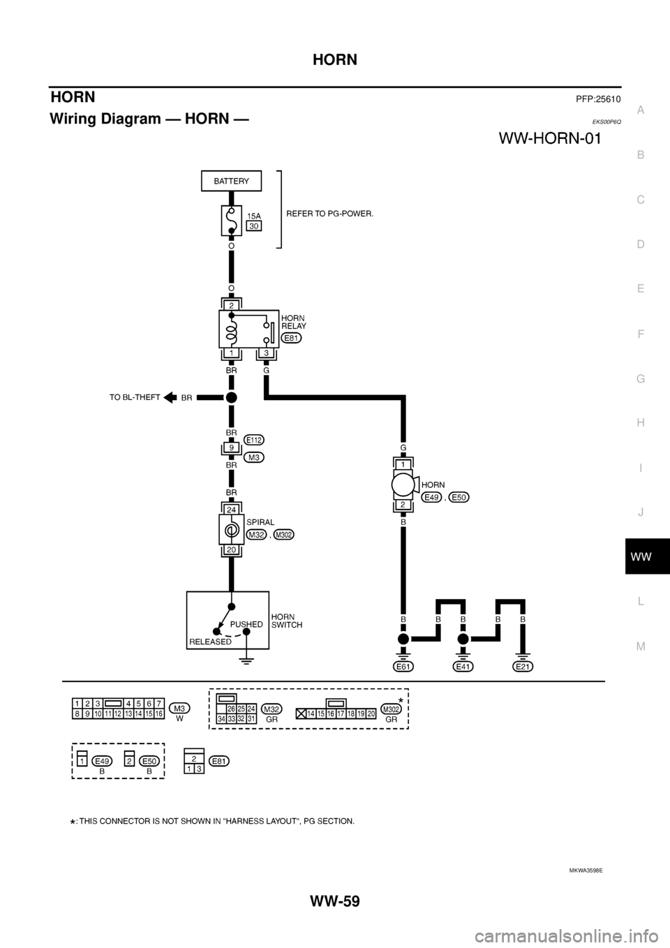
Wiring Diagram — HORN —EKS00P6Q
MKWA3598E
Trending: instrument panel, trunk release, change time, trip computer, jacking, wheel torque, lug pattern
