diagram NISSAN NAVARA 2005 Repair Owner's Guide
[x] Cancel search | Manufacturer: NISSAN, Model Year: 2005, Model line: NAVARA, Model: NISSAN NAVARA 2005Pages: 3171, PDF Size: 49.59 MB
Page 588 of 3171
BL-4
PRECAUTIONS
PRECAUTIONS
PFP:00001
Precautions for Supplemental Restraint System (SRS) “AIR BAG” and “SEAT
BELT PRE-TENSIONER”
EIS00DHW
The Supplemental Restraint System such as “AIR BAG” and “SEAT BELT PRE-TENSIONER”, used along
with a front seat belt, helps to reduce the risk or severity of injury to the driver and front passenger for certain
types of collision. Information necessary to service the system safely is included in the SRS and SB section of
this Service Manual.
WARNING:
lTo avoid rendering the SRS inoperative, which could increase the risk of personal injury or death
in the event of a collision which would result in air bag inflation, all maintenance must be per-
formed by an authorized NISSAN/INFINITI dealer.
lImproper maintenance, including incorrect removal and installation of the SRS, can lead to per-
sonal injury caused by unintentional activation of the system. For removal of Spiral Cable and Air
Bag Module, see the SRS section.
lDo not use electrical test equipment on any circuit related to the SRS unless instructed to in this
Service Manual. SRS wiring harnesses can be identified by yellow and/or orange harnesses or
harness connectors.
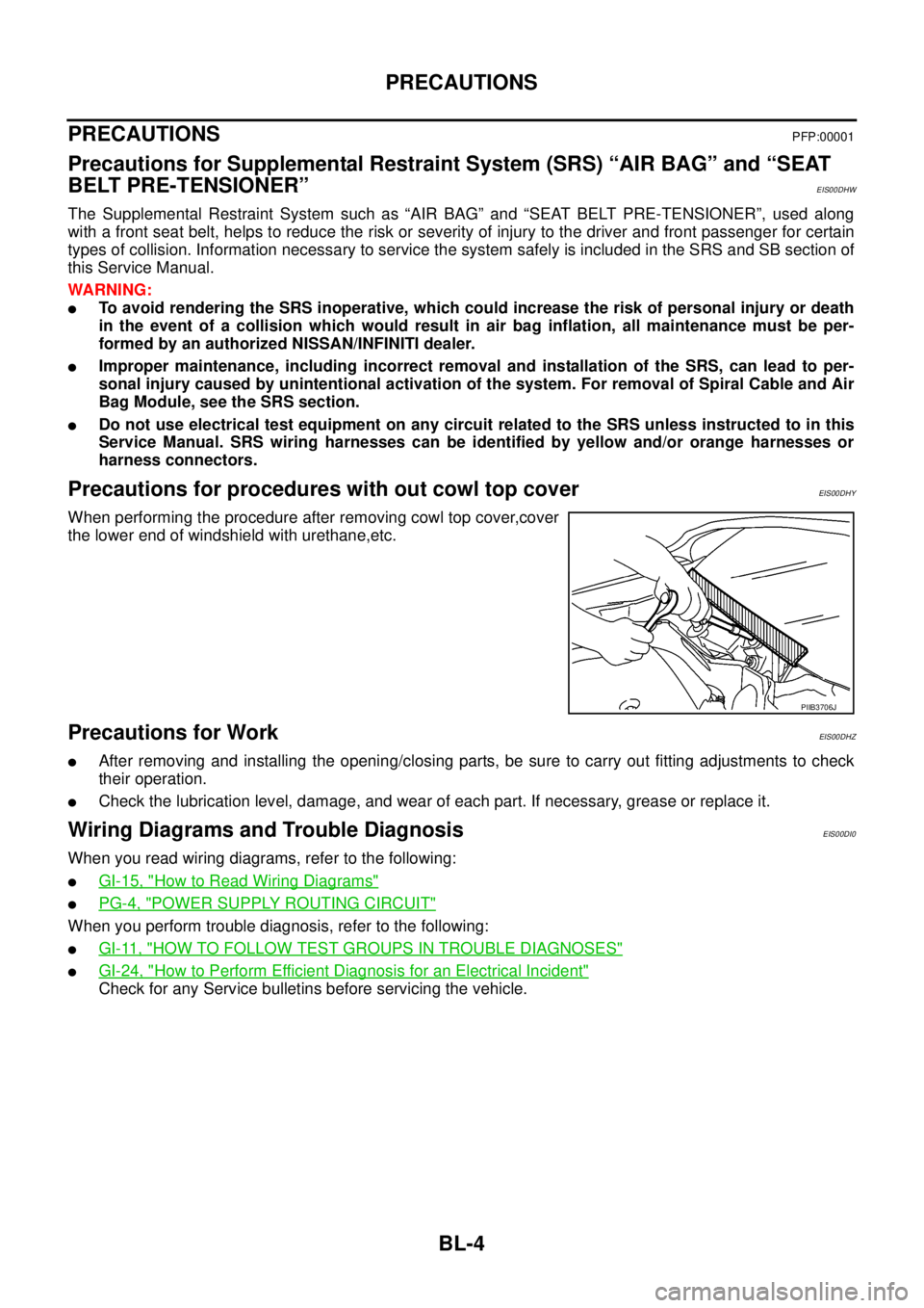
Precautions for procedures with out cowl top coverEIS00DHY
When performing the procedure after removing cowl top cover,cover
the lower end of windshield with urethane,etc.
Precautions for WorkEIS00DHZ
lAfter removing and installing the opening/closing parts, be sure to carry out fitting adjustments to check
their operation.
lCheck the lubrication level, damage, and wear of each part. If necessary, grease or replace it.
Wiring Diagrams and Trouble DiagnosisEIS00DI0
When you read wiring diagrams, refer to the following:
lGI-15, "How to Read Wiring Diagrams"
lPG-4, "POWER SUPPLY ROUTING CIRCUIT"
When you perform trouble diagnosis, refer to the following:
lGI-11, "HOW TO FOLLOW TEST GROUPS IN TROUBLE DIAGNOSES"
lGI-24, "How to Perform Efficient Diagnosis for an Electrical Incident"
Check for any Service bulletins before servicing the vehicle.
PIIB3706J
Page 611 of 3171
POWERDOORLOCKSYSTEM
BL-27
C
D
E
F
G
H
J
K
L
MA
B
BL
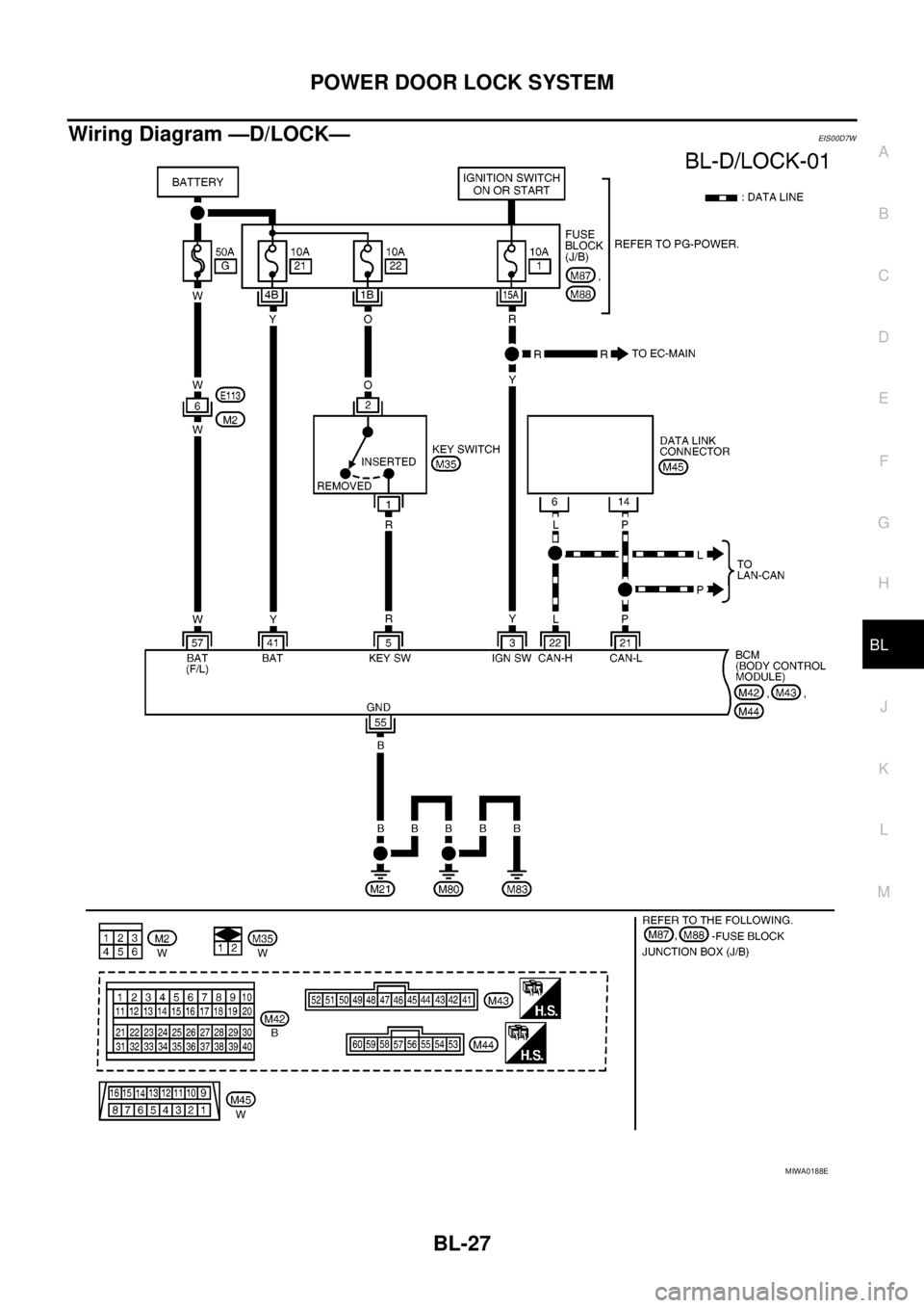
Wiring Diagram —D/LOCK—EIS00D7W
MIWA0188E
Page 645 of 3171
POWER DOOR LOCK — SUPER LOCK —
BL-61
C
D
E
F
G
H
J
K
L
MA
B
BL
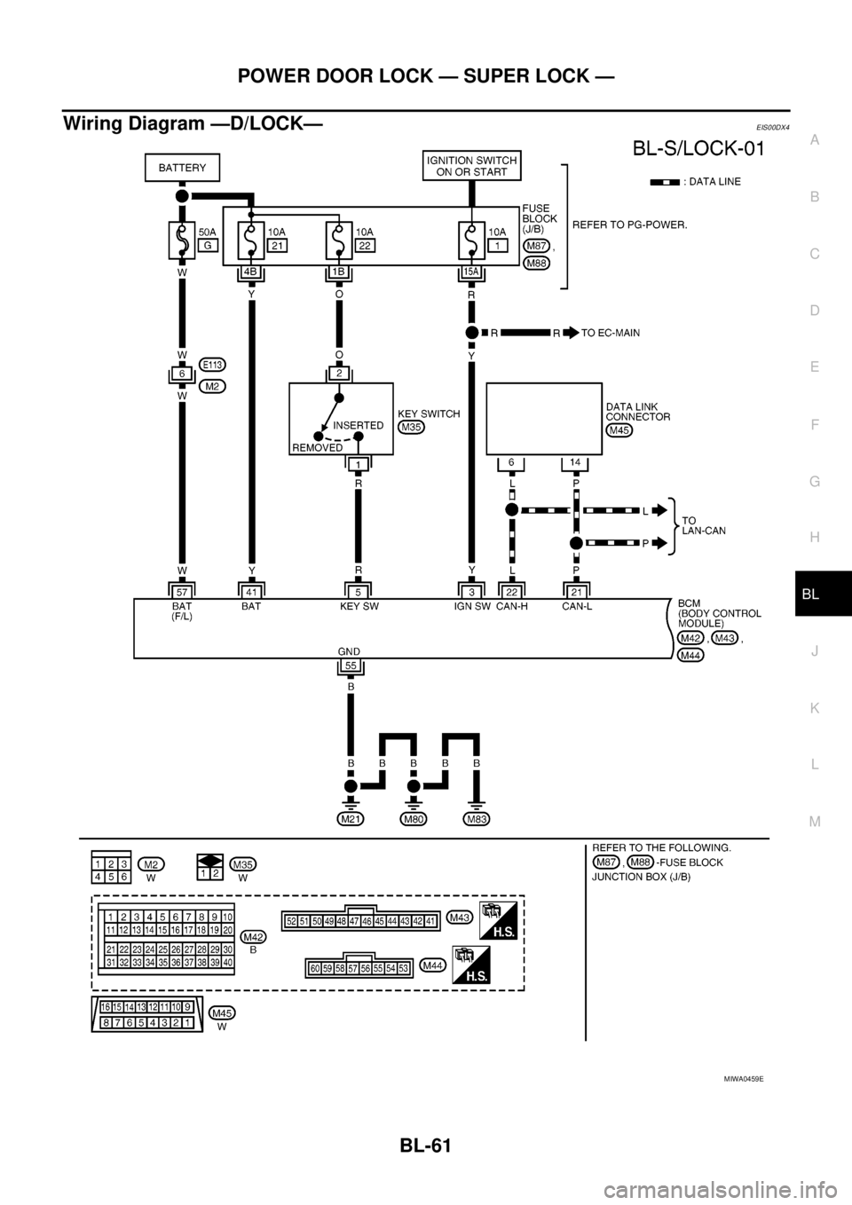
Wiring Diagram —D/LOCK—EIS00DX4
MIWA0459E
Page 677 of 3171

MULTI-REMOTE CONTROL SYSTEM
BL-93
C
D
E
F
G
H
J
K
L
MA
B
BL
WiringDiagram—MULTI—ForLHDModelsEIS00DBG
MIWA0214E
Page 681 of 3171
MULTI-REMOTE CONTROL SYSTEM
BL-97
C
D
E
F
G
H
J
K
L
MA
B
BL
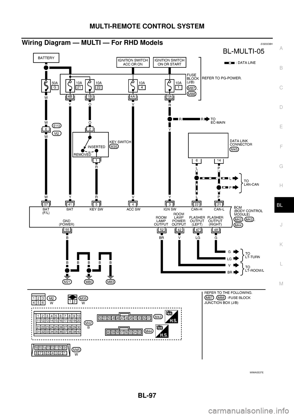
Wiring Diagram — MULTI — For RHD ModelsEIS00DBH
MIWA0537E
Page 727 of 3171
THEFT WARNING SYSTEM
BL-143
C
D
E
F
G
H
J
K
L
MA
B
BL
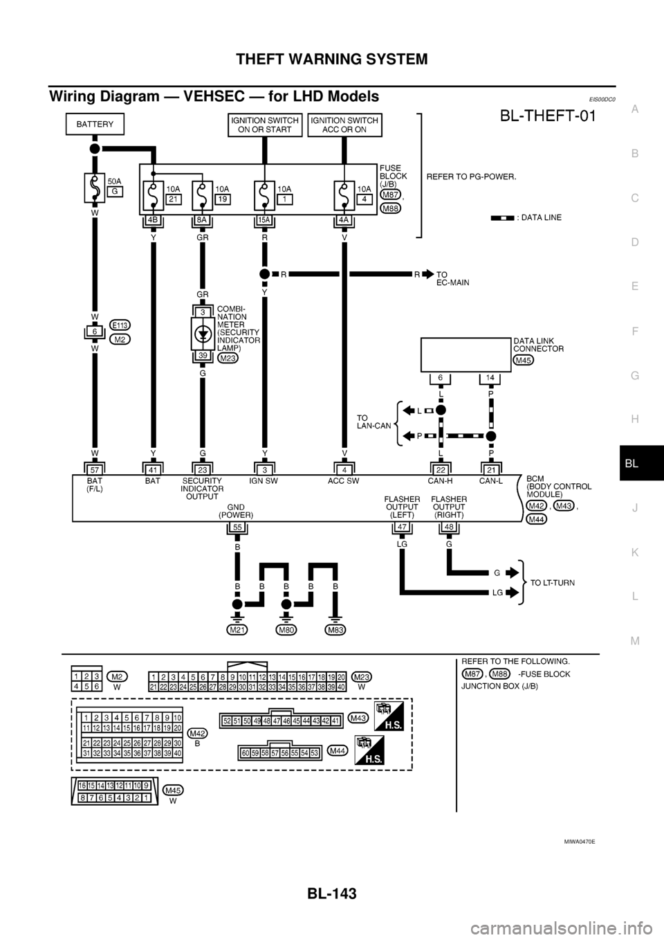
Wiring Diagram — VEHSEC — for LHD ModelsEIS00DC0
MIWA0470E
Page 733 of 3171
THEFT WARNING SYSTEM
BL-149
C
D
E
F
G
H
J
K
L
MA
B
BL
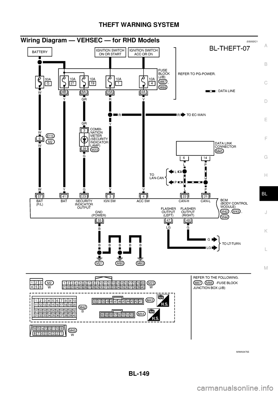
Wiring Diagram — VEHSEC — for RHD ModelsEIS00DC1
MIWA0475E
Page 757 of 3171
NATS(NISSAN ANTI-THEFT SYSTEM)
BL-173
C
D
E
F
G
H
J
K
L
MA
B
BL
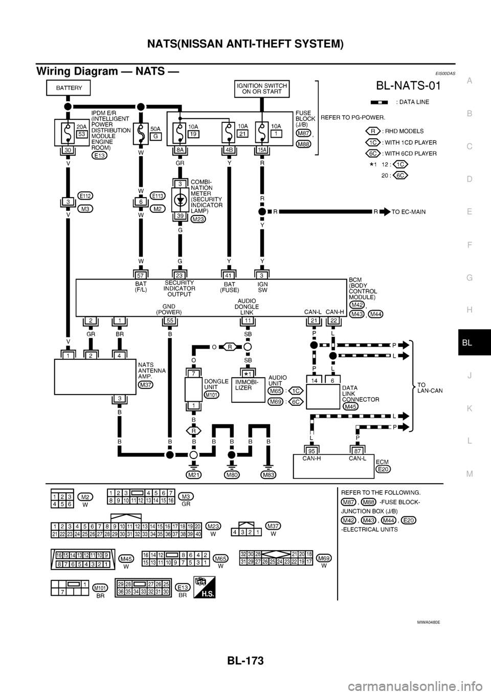
Wiring Diagram — NATS —EIS00DAS
MIWA0480E
Page 823 of 3171
BRC-1
BRAKE CONTROL SYSTEM
F BRAKES
CONTENTS
C
D
E
G
H
I
J
K
L
M
SECTIONBRC
A
B
BRC
BRAKE CONTROL SYSTEM
ABS
PRECAUTIONS .......................................................... 3
Precautions for Supplemental Restraint System
(SRS)“AIRBAG”and“SEATBELTPRE-TEN-
SIONER” .................................................................. 3
Precautions for Brake System .................................. 3
Precautions for Brake Control .................................. 3
PREPARATION ........................................................... 4
Special Service Tools (SST) ..................................... 4
SYSTEM DESCRIPTION ............................................ 5
System Diagram ....................................................... 5
Functions .................................................................. 5
Operation That Is Not “System Error” ...................... 5
Fail-Safe Function .................................................... 5
ABS, EBD SYSTEM .............................................. 5
Hydraulic Circuit Diagram ........................................ 6
CAN COMMUNICATION ............................................ 7
System Description .................................................. 7
TROUBLE DIAGNOSIS .............................................. 8
How to Perform Trouble Diagnosis for Quick and
Accurate Repair ....................................................... 8
INTRODUCTION ................................................... 8
DIAGNOSIS FLOWCHART .................................. 9
ASKING COMPLAINTS ...................................... 10
EXAMPLE OF DIAGNOSIS SHEET ................... 10
Component Parts Location ...................................... 11
Schematic — ABS — ............................................. 12
Wiring Diagram — ABS — ..................................... 13
CONSULT- II Functions .......................................... 17
CONSULT-II MAIN FUNCTION ........................... 17
CONSULT-II BASIC OPERATION PROCEDURE
... 17
Self-Diagnosis ........................................................ 18
OPERATION PROCEDURE ............................... 18
ERASE MEMORY ............................................... 18
DISPLAY ITEM LIST ........................................... 18
Data Monitor ........................................................... 20
OPERATION PROCEDURE ............................... 20
DISPLAY ITEM LIST ........................................... 20Active Test .............................................................. 21
OPERATION PROCEDURE ................................ 21
SOLENOID VALVE .............................................. 22
ABS MOTOR ....................................................... 22
For Fast and Accurate Diagnosis ........................... 23
PRECAUTIONS FOR DIAGNOSIS ..................... 23
Basic Inspection ..................................................... 23
BASIC INSPECTION 1 BRAKE FLUID LEVEL,
LEAKS, AND BRAKE PADS ................................ 23
BASIC INSPECTION 2 POWER SYSTEM TER-
MINAL LOOSENESS AND BATTERY INSPEC-
TION .................................................................... 23
BASIC INSPECTION 3 ABS WARNING LAMP
AND BRAKE WARNING LAMP INSPECTION .... 24
Inspection 1 Wheel Sensor System ........................ 24
Inspection 2 ABS Actuator and Electric Unit (Control
Unit) ........................................................................ 26
Inspection 3 ABS Actuator Relay or ABS Motor
Relay Circuit ........................................................... 26
Inspection 4 CAN Communication Circuit .............. 28
Inspection 5 ABS Actuator and Electric Unit (Control
Unit) Power Supply and Ground Circuit .................. 28
Inspection 6 Brake Fluid Level Switch Circuit ......... 30
Inspection 7 Parking Brake Switch Circuit .............. 32
Inspection 8 Warning lamp system ......................... 33
Symptom 1: Excessive ABS Function Operation
Frequency ............................................................... 33
Symptom 2: Unexpected Pedal Reaction ............... 34
Symptom 3: The Stopping Distance Is Long .......... 34
Symptom 4: ABS Function Does Not Operate ....... 35
Symptom 5: Pedal Vibration or ABS Operation
Sound Occurs ......................................................... 35
Symptom 6: ABS Warning Lamp Indication Is Not
Normal .................................................................... 35
WHEEL SENSORS ................................................... 37
Removal and Installation ........................................ 37
REMOVAL ........................................................... 38
INSTALLATION ................................................... 38
Page 827 of 3171

SYSTEM DESCRIPTION
BRC-5
[ABS]
C
D
E
G
H
I
J
K
L
MA
B
BRC
SYSTEM DESCRIPTIONPFP:00000
System DiagramEFS005TJ
FunctionsEFS005TK
ABS
lThe Anti-Lock Brake System is a function that detects wheel revolution while braking, and it improves
handling stability during sudden braking by electrically preventing 4 wheels lock. Maneuverability is also
improved for avoiding obstacles.
lElectrical system diagnosis by CONSULT-II is available.
EBD
lElectronic Brake Distributor is a function that detects subtle slippages between the front and rear tyre dur-
ing braking, and it improves handling stability by electrically controlling the brake fluid pressure which
results in reduced rear tyre slippage.
lElectrical system diagnosis by CONSULT-II is available.
Operation That Is Not “System Error”EFS005TL
ABS
lWhen starting engine or just after starting vehicle, brake pedal may vibrate or the motor operating noise
may be heard from engine room. This is a normal states of the operation check.
lDuring ABS operation, brake pedal lightly vibrates and a mechanical noise may be heard. This is normal.
lStopping distance may be longer than that of vehicles without ABS when vehicle drives on rough, gravel,
or snow-covered (fresh, deep snow) roads.
Fail-Safe FunctionEFS005TM
ABS, EBD SYSTEM
In case of electrical malfunction with ABS, ABS warning lamp will turn on. In case of electrical incidents with
EBD, brake warning lamp and ABS warning lamp will turn on. Simultaneously, ABS become one of following
conditions of Fail-Safe function.
1. For ABS malfunction, only EBD is activated and condition of vehicle is same condition of vehicles without
ABS system.
NOTE:
ABS self-diagnosis sound may be heard.That is a normal condition because a self-diagnosis for “Ignition
switch ON” and “The first starting” are being performed.
2. For EBD malfunction, EBD and ABS become inoperative, and condition of vehicle is same as condition of
vehicles without ABS, EBD system.
SFIA3001E