sensor NISSAN NAVARA 2005 Repair Service Manual
[x] Cancel search | Manufacturer: NISSAN, Model Year: 2005, Model line: NAVARA, Model: NISSAN NAVARA 2005Pages: 3171, PDF Size: 49.59 MB
Page 91 of 3171
TROUBLE DIAGNOSIS
AT-83
D
E
F
G
H
I
J
K
L
MA
B
AT
DATA MONITOR MODE
Operation Procedure
1. PerformAT-79, "CONSULT-II SETTING PROCEDURE".
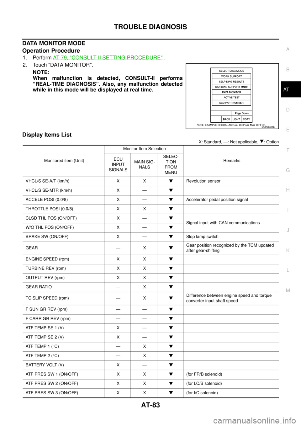
2. Touch “DATA MONITOR”.
NOTE:
When malfunction is detected, CONSULT-II performs
“REAL-TIME DIAGNOSIS”. Also, any malfunction detected
while in this mode will be displayed at real time.
Display Items List
X: Standard, —: Not applicable, : Option
BCIA0031E
Monitored item (Unit)Monitor Item Selection
Remarks ECU
INPUT
SIGNALSMAIN SIG-
NALSSELEC-
TION
FROM
MENU
VHCL/S SE-A/T (km/h) X X Revolution sensor
VHCL/S SE-MTR (km/h) X —
ACCELE POSI (0.0/8) X — Accelerator pedal position signal
THROTTLE POSI (0.0/8) X X
CLSD THL POS (ON/OFF) X —
Signal input with CAN communications
W/O THL POS (ON/OFF) X —
BRAKE SW (ON/OFF) X — Stop lamp switch
GEAR — XGear position recognized by the TCM updated
after gear-shifting
ENGINE SPEED (rpm) X X
TURBINE REV (rpm) X X
OUTPUT REV (rpm) X X
GEAR RATIO — X
TC SLIP SPEED (rpm) — XDifference between engine speed and torque
converter input shaft speed
F SUN GR REV (rpm) — —
F CARR GR REV (rpm) — —
ATFTEMPSE1(V) X —
ATFTEMPSE2(V) X —
AT F T E M P 1 (°C) — X
AT F T E M P 2 (°C) — X
BATTERY VOLT (V) X —
ATF PRES SW 1 (ON/OFF) X X (for FR/B solenoid)
ATF PRES SW 2 (ON/OFF) X X (for LC/B solenoid)
ATF PRES SW 3 (ON/OFF) X X (for I/C solenoid)
Page 98 of 3171
AT-90
TROUBLE DIAGNOSIS
Judgement Self-diagnosis Code
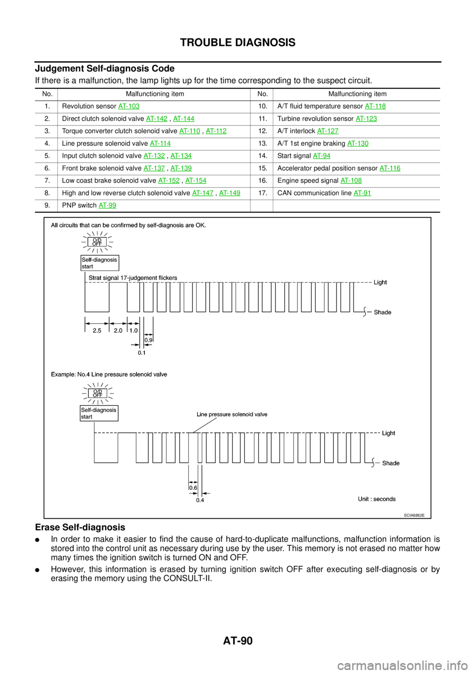
If there is a malfunction, the lamp lights up for the time corresponding to the suspect circuit.
Erase Self-diagnosis
lIn order to make it easier to find the cause of hard-to-duplicate malfunctions, malfunction information is
stored into the control unit as necessary during use by the user. This memory is not erased no matter how
many times the ignition switch is turned ON and OFF.
lHowever, this information is erased by turning ignition switch OFF after executing self-diagnosis or by
erasing the memory using the CONSULT-II.
No. Malfunctioning item No. Malfunctioning item
1. Revolution sensorAT- 1 0 3
10. A/T fluid temperature sensorAT- 11 8
2. Direct clutch solenoid valveAT- 1 4 2,AT-14411. Turbine revolution sensorAT- 1 2 3
3. Torque converter clutch solenoid valveAT- 11 0,AT- 11 212. A/T interlockAT-127
4. Line pressure solenoid valveAT- 11 413. A/T 1st engine brakingAT-130
5. Input clutch solenoid valveAT- 1 3 2,AT- 1 3 414. Start signalAT- 9 4
6. Front brake solenoid valveAT-137,AT- 1 3 915. Accelerator pedal position sensorAT- 11 6
7. Low coast brake solenoid valveAT- 1 5 2,AT- 1 5 416. Engine speed signalAT-108
8. High and low reverse clutch solenoid valveAT-147,AT- 1 4 917. CAN communication lineAT- 9 1
9. PNP switchAT- 9 9
SCIA6862E
Page 105 of 3171
DTC P0615 START SIGNAL CIRCUIT
AT-97
D
E
F
G
H
I
J
K
L
MA
B
AT
3.CHECK TERMINAL CORD ASSEMBLY
1. Remove control valve with TCM. Refer toAT- 2 1 8 , "
Control Valve With TCM and A/T Fluid Temperature
Sensor 2".
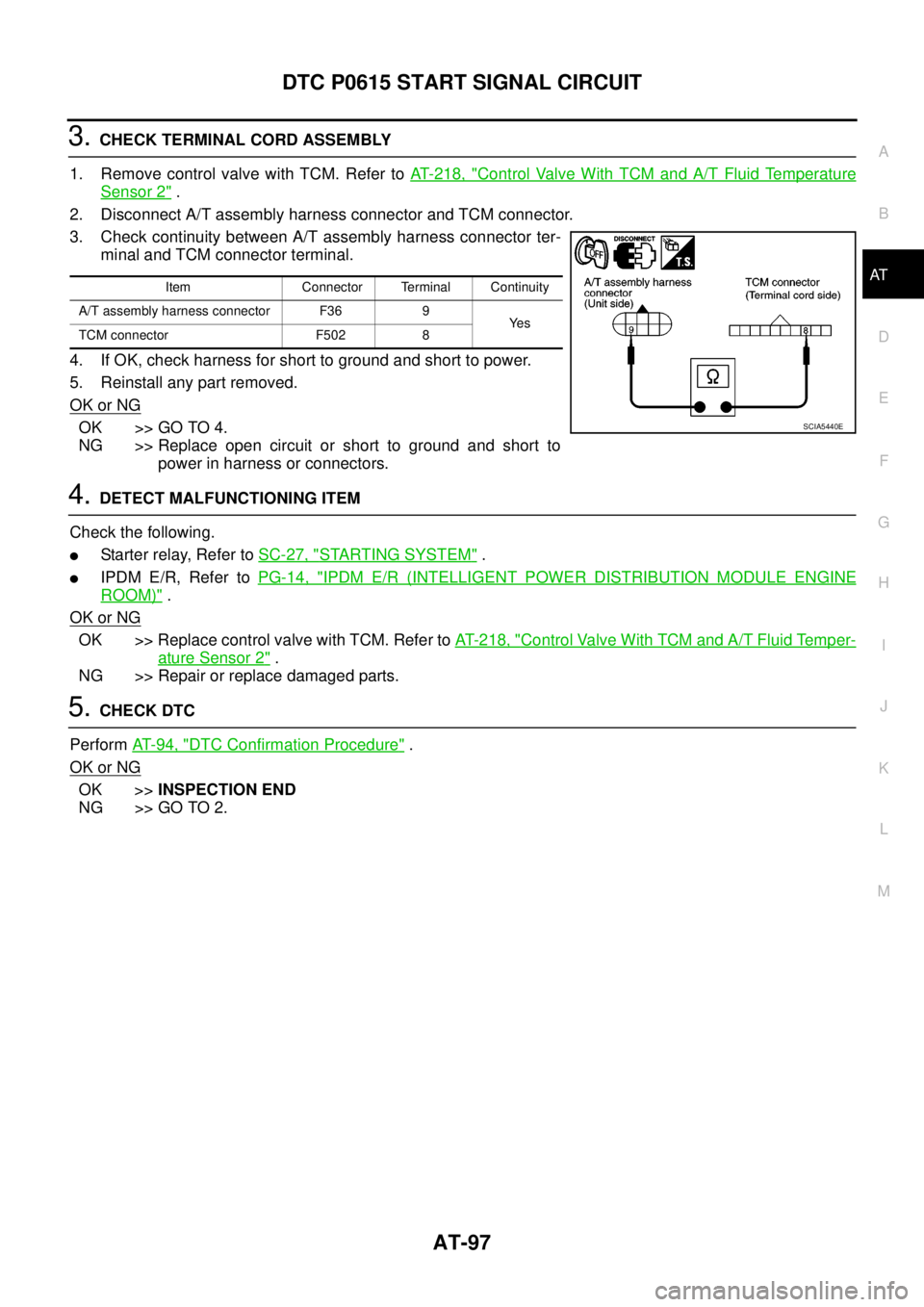
2. Disconnect A/T assembly harness connector and TCM connector.
3. Check continuity between A/T assembly harness connector ter-
minal and TCM connector terminal.
4. If OK, check harness for short to ground and short to power.
5. Reinstall any part removed.
OK or NG
OK >> GO TO 4.
NG >> Replace open circuit or short to ground and short to
power in harness or connectors.
4.DETECT MALFUNCTIONING ITEM
Check the following.
lStarter relay, Refer toSC-27, "STARTING SYSTEM".
lIPDM E/R, Refer toPG-14, "IPDM E/R (INTELLIGENT POWER DISTRIBUTION MODULE ENGINE
ROOM)".
OK or NG
OK >> Replace control valve with TCM. Refer toAT- 2 1 8 , "Control Valve With TCM and A/T Fluid Temper-
ature Sensor 2".
NG >> Repair or replace damaged parts.
5.CHECK DTC
PerformAT-94, "
DTC Confirmation Procedure".
OK or NG
OK >>INSPECTION END
NG >> GO TO 2.
Item Connector Terminal Continuity
A/T assembly harness connector F36 9
Ye s
TCM connector F502 8
SCIA5440E
Page 106 of 3171
AT-98
DTC P0700 TCM
DTC P0700 TCM
PFP:31036
DescriptionECS00FXP
TCM consists of a microcomputer and connectors for signal input and output and for power supply. TCM con-
trols A/T.
On Board Diagnosis LogicECS00FXQ
Diagnostic trouble code “P0700 TCM” with CONSULT-II is detected when TCM is malfunctioning.
Possible CauseECS00FXR
TCM
DTC Confirmation ProcedureECS00FXS
NOTE:
If “DTC Confirmation Procedure” has been previously performed, always turn ignition switch OFF and
wait at least 10 seconds before performing the next test.
After the repair, perform the following procedure to confirm the malfunction is eliminated.
WITH CONSULT-II
1. Turn ignition switch ON. (Do not start engine.)
2. Select “ECU INPUT SIGNALS” or “MAIN SIGNALS” in “DATA
MONITOR” mode for “A/T” with CONSULT-II.
3. Start engine.
4. Run engine for at least 2 consecutive seconds at idle speed.
5. If DTC is detected, go toAT-98, "
Diagnostic Procedure".
Diagnostic ProcedureECS00FXT
1.CHECK DTC
With CONSULT-II
1. Turn ignition switch ON. (Do not start engine.)
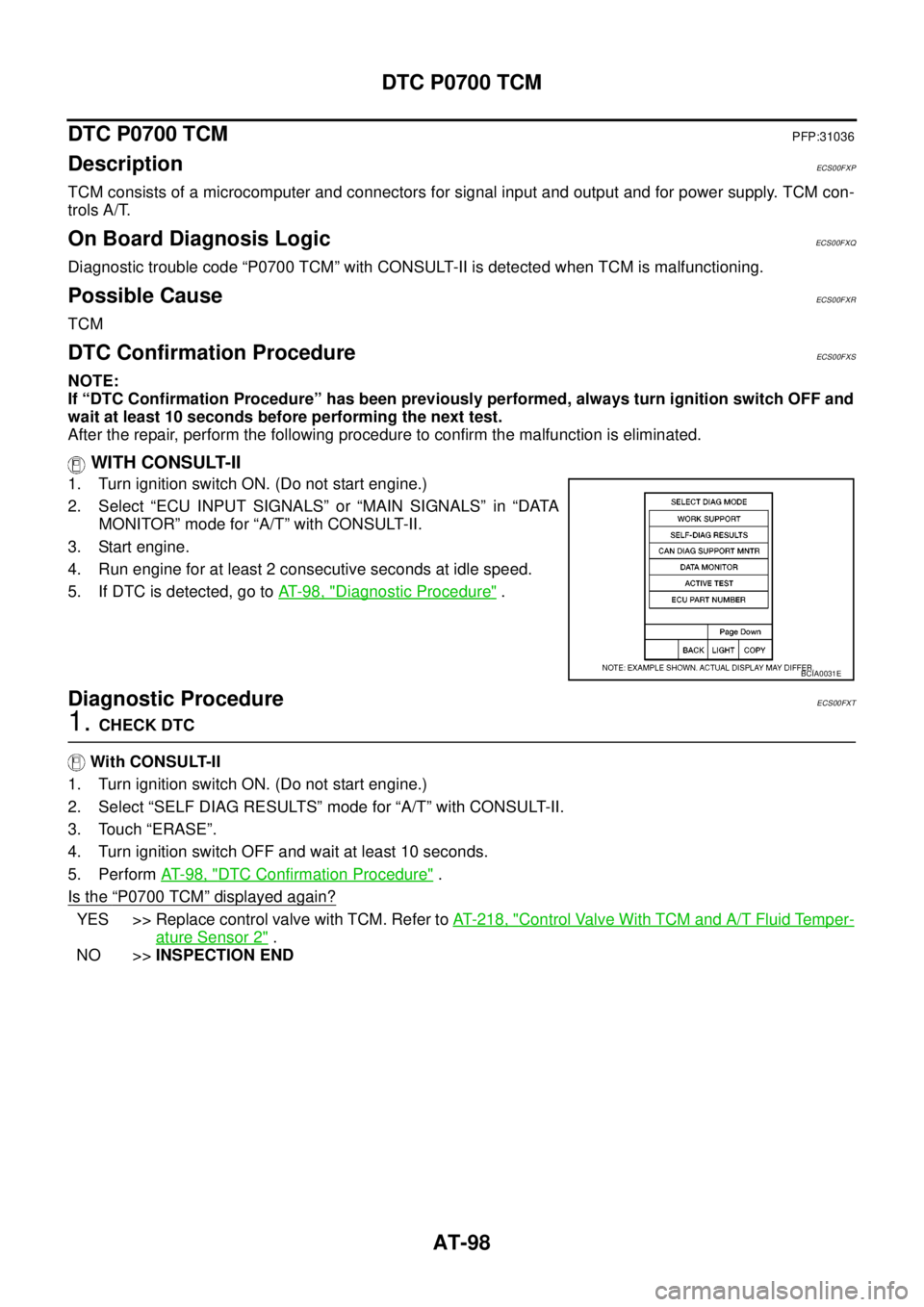
2. Select “SELF DIAG RESULTS” mode for “A/T” with CONSULT-II.
3. Touch “ERASE”.
4. Turn ignition switch OFF and wait at least 10 seconds.
5. PerformAT- 9 8 , "
DTC Confirmation Procedure".
Is the
“P0700 TCM”displayed again?
YES >> Replace control valve with TCM. Refer toAT- 2 1 8 , "Control Valve With TCM and A/T Fluid Temper-
ature Sensor 2".
NO >>INSPECTION END
BCIA0031E
Page 110 of 3171
AT-102
DTC P0705 PARK/NEUTRAL POSITION SWITCH
4.CHECK SUB-HARNESS
1. Remove control valve with TCM. Refer toAT- 2 1 8 , "
Control Valve With TCM and A/T Fluid Temperature
Sensor 2".
2. Disconnect park/neutral position switch connector and TCM connector.
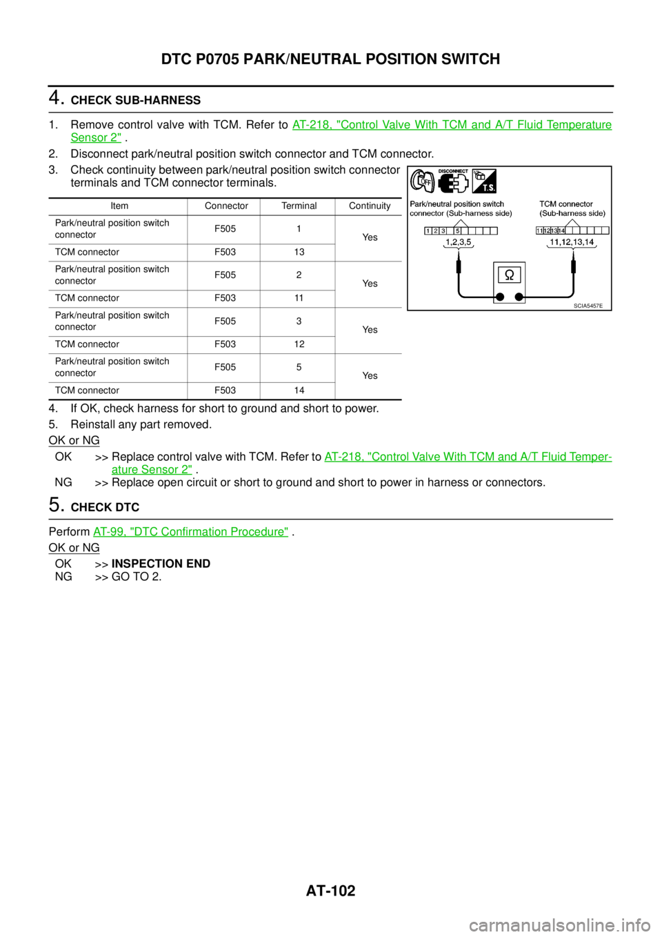
3. Check continuity between park/neutral position switch connector
terminals and TCM connector terminals.
4. If OK, check harness for short to ground and short to power.
5. Reinstall any part removed.
OK or NG
OK >> Replace control valve with TCM. Refer toAT- 2 1 8 , "Control Valve With TCM and A/T Fluid Temper-
ature Sensor 2".
NG >> Replace open circuit or short to ground and short to power in harness or connectors.
5.CHECK DTC
PerformAT-99, "
DTC Confirmation Procedure".
OK or NG
OK >>INSPECTION END
NG >> GO TO 2.
Item Connector Terminal Continuity
Park/neutral position switch
connectorF505 1
Ye s
TCM connector F503 13
Park/neutral position switch
connectorF505 2
Ye s
TCM connector F503 11
Park/neutral position switch
connectorF505 3
Ye s
TCM connector F503 12
Park/neutral position switch
connectorF505 5
Ye s
TCM connector F503 14
SCIA5457E
Page 111 of 3171
DTC P0720 VEHICLE SPEED SENSOR A/T (REVOLUTION SENSOR)
AT-103
D
E
F
G
H
I
J
K
L
MA
B
AT
DTC P0720 VEHICLE SPEED SENSOR A/T (REVOLUTION SENSOR)PFP:32702
DescriptionECS00FY1
Revolution sensor detects the revolution of the idler gear parking pawl lock gear and emits a pulse signal. The
pulse signal is sent to TCM which converts it into vehicle speed.
CONSULT-II Reference ValueECS00FY2
On Board Diagnosis LogicECS00FY3
Diagnostic trouble code “P0720 VEH SPD SEN/CIR AT” with CONSULT-II or 1st judgement flicker without
CONSULT-II is detected under the following conditions.
lWhen TCM does not receive the proper voltage signal from the sensor.
lAfter ignition switch is turned ON, irregular signal input from vehicle speed sensor MTR before the vehicle
starts moving.
Possible CauseECS00FY4
lHarness or connectors
(The sensor circuit is open or shorted.)
lRevolution sensor
lVehicle speed sensor MTR
DTC Confirmation ProcedureECS00FY5
CAUTION:
lAlways drive vehicle at a safe speed.
lBe careful not to rev engine into the red zone on the tachometer.
NOTE:
If “DTC Confirmation Procedure” has been previously performed, always turn ignition switch OFF and
wait at least 10 seconds before performing the next test.
After the repair, perform the following procedure to confirm the malfunction is eliminated.
WITH CONSULT-II
1. Turn ignition switch ON. (Do not start engine.)
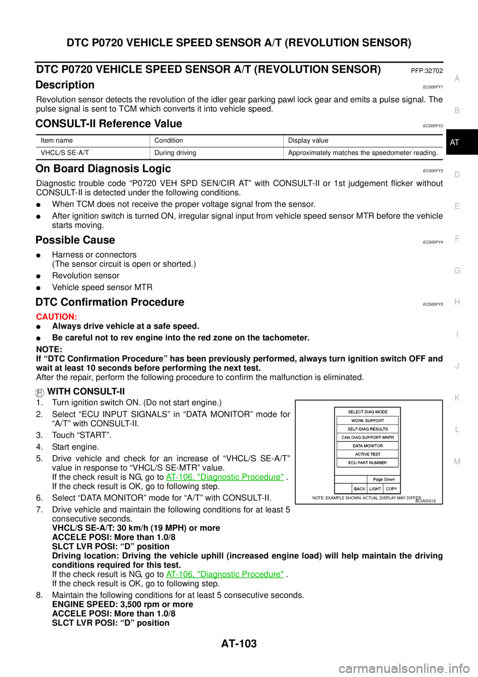
2. Select “ECU INPUT SIGNALS” in “DATA MONITOR” mode for
“A/T” with CONSULT-II.
3. Touch “START”.
4. Start engine.
5. Drive vehicle and check for an increase of “VHCL/S SE-A/T”
value in response to “VHCL/S SE-MTR” value.
If the check result is NG, go toAT- 1 0 6 , "
Diagnostic Procedure".
If the check result is OK, go to following step.
6. Select “DATA MONITOR” mode for “A/T” with CONSULT-II.
7. Drive vehicle and maintain the following conditions for at least 5
consecutive seconds.
VHCL/S SE-A/T: 30 km/h (19 MPH) or more
ACCELE POSI: More than 1.0/8
SLCT LVR POSI: “D” position
Driving location: Driving the vehicle uphill (increased engine load) will help maintain the driving
conditions required for this test.
If the check result is NG, go toAT- 1 0 6 , "
Diagnostic Procedure".
If the check result is OK, go to following step.
8. Maintain the following conditions for at least 5 consecutive seconds.
ENGINE SPEED: 3,500 rpm or more
ACCELE POSI: More than 1.0/8
SLCT LVR POSI: “D” position
Item name Condition Display value
VHCL/S SE-A/T During driving Approximately matches the speedometer reading.
BCIA0031E
Page 112 of 3171

AT-104
DTC P0720 VEHICLE SPEED SENSOR A/T (REVOLUTION SENSOR)
Driving location: Driving the vehicle uphill (increased engine load) will help maintain the driving
conditions required for this test.
If is detected, go toAT- 1 0 6 , "
Diagnostic Procedure".
WITHOUT CONSULT-II
1. Start engine.
2. Drive vehicle and maintain the following conditions for at least 5 consecutive seconds.
Vehicle speed: 30 km/h (19 MPH) or more
Accelerator opening: More than 1.0/8
Selector lever position: “D” position
Driving location: Driving the vehicle uphill (increased engine load) will help maintain the driving
conditions required for this test.
3. Perform self-diagnosis. Refer toAT-89, "
Diagnostic Procedure Without CONSULT-II".
4. If DTC is detected, go toAT- 1 0 6 , "
Diagnostic Procedure".
Page 113 of 3171
DTC P0720 VEHICLE SPEED SENSOR A/T (REVOLUTION SENSOR)
AT-105
D
E
F
G
H
I
J
K
L
MA
B
AT
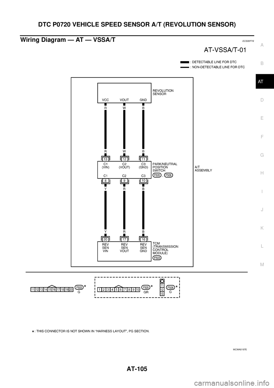
Wiring Diagram — AT — VSSA/TECS00FY6
MCWA0197E
Page 114 of 3171
AT-106
DTC P0720 VEHICLE SPEED SENSOR A/T (REVOLUTION SENSOR)
Diagnostic Procedure
ECS00FY7
1.CHECK INPUT SIGNAL
With CONSULT-II
1. Turn ignition switch ON. (Do not start engine)
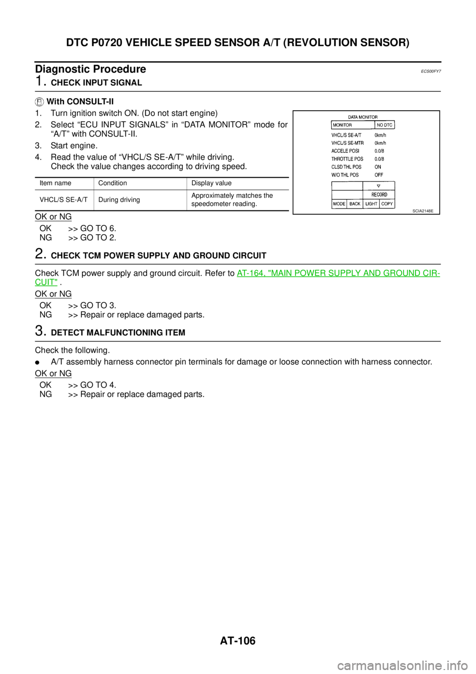
2. Select “ECU INPUT SIGNALS” in “DATA MONITOR” mode for
“A/T” with CONSULT-II.
3. Start engine.
4. Read the value of “VHCL/S SE-A/T” while driving.
Check the value changes according to driving speed.
OK or NG
OK >> GO TO 6.
NG >> GO TO 2.
2.CHECK TCM POWER SUPPLY AND GROUND CIRCUIT
Check TCM power supply and ground circuit. Refer toAT- 1 6 4 , "
MAIN POWER SUPPLY AND GROUND CIR-
CUIT".
OK or NG
OK >> GO TO 3.
NG >> Repair or replace damaged parts.
3.DETECT MALFUNCTIONING ITEM
Check the following.
lA/T assembly harness connector pin terminals for damage or loose connection with harness connector.
OK or NG
OK >> GO TO 4.
NG >> Repair or replace damaged parts.
Item name Condition Display value
VHCL/S SE-A/T During drivingApproximately matches the
speedometer reading.
SCIA2148E
Page 115 of 3171
DTC P0720 VEHICLE SPEED SENSOR A/T (REVOLUTION SENSOR)
AT-107
D
E
F
G
H
I
J
K
L
MA
B
AT
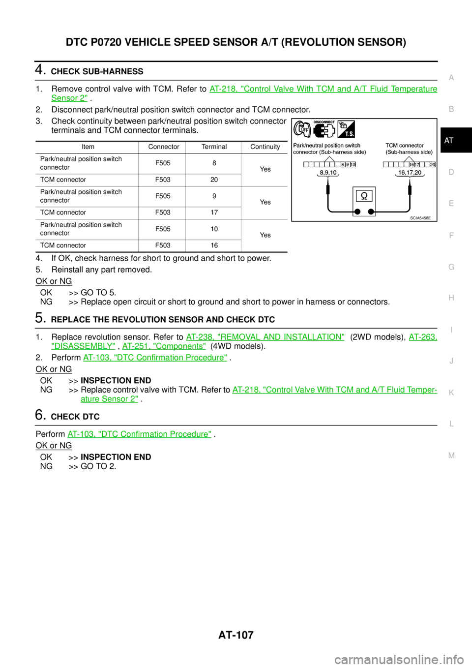
4.CHECK SUB-HARNESS
1. Remove control valve with TCM. Refer toAT- 2 1 8 , "
Control Valve With TCM and A/T Fluid Temperature
Sensor 2".
2. Disconnect park/neutral position switch connector and TCM connector.
3. Check continuity between park/neutral position switch connector
terminals and TCM connector terminals.
4. If OK, check harness for short to ground and short to power.
5. Reinstall any part removed.
OK or NG
OK >> GO TO 5.
NG >> Replace open circuit or short to ground and short to power in harness or connectors.
5.REPLACE THE REVOLUTION SENSOR AND CHECK DTC
1. Replace revolution sensor. Refer toAT- 2 3 8 , "
REMOVAL AND INSTALLATION"(2WD models),AT- 2 6 3 ,
"DISASSEMBLY",AT- 2 5 1 , "Components"(4WD models).
2. PerformAT- 1 0 3 , "
DTC Confirmation Procedure".
OK or NG
OK >>INSPECTION END
NG >> Replace control valve with TCM. Refer toAT- 2 1 8 , "
Control Valve With TCM and A/T Fluid Temper-
ature Sensor 2".
6.CHECK DTC
PerformAT- 1 0 3 , "
DTC Confirmation Procedure".
OK or NG
OK >>INSPECTION END
NG >> GO TO 2.
Item Connector Terminal Continuity
Park/neutral position switch
connectorF505 8
Ye s
TCM connector F503 20
Park/neutral position switch
connectorF505 9
Ye s
TCM connector F503 17
Park/neutral position switch
connectorF505 10
Ye s
TCM connector F503 16
SCIA5458E