NISSAN NAVARA 2005 Repair Workshop Manual
Manufacturer: NISSAN, Model Year: 2005, Model line: NAVARA, Model: NISSAN NAVARA 2005Pages: 3171, PDF Size: 49.59 MB
Page 701 of 3171
DOOR
BL-117
C
D
E
F
G
H
J
K
L
MA
B
BL
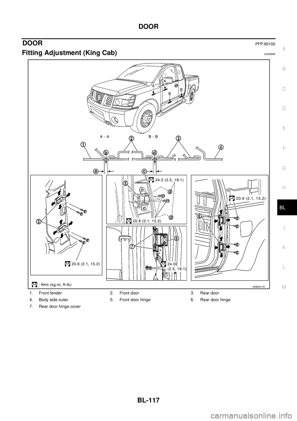
DOORPFP:80100
Fitting Adjustment (King Cab)EIS00B69
1. Front fender 2. Front door 3. Rear door
4. Body side outer 5. Front door hinge 6. Rear door hinge
7. Rear door hinge cover
MIIB0917E
Page 702 of 3171
BL-118
DOOR
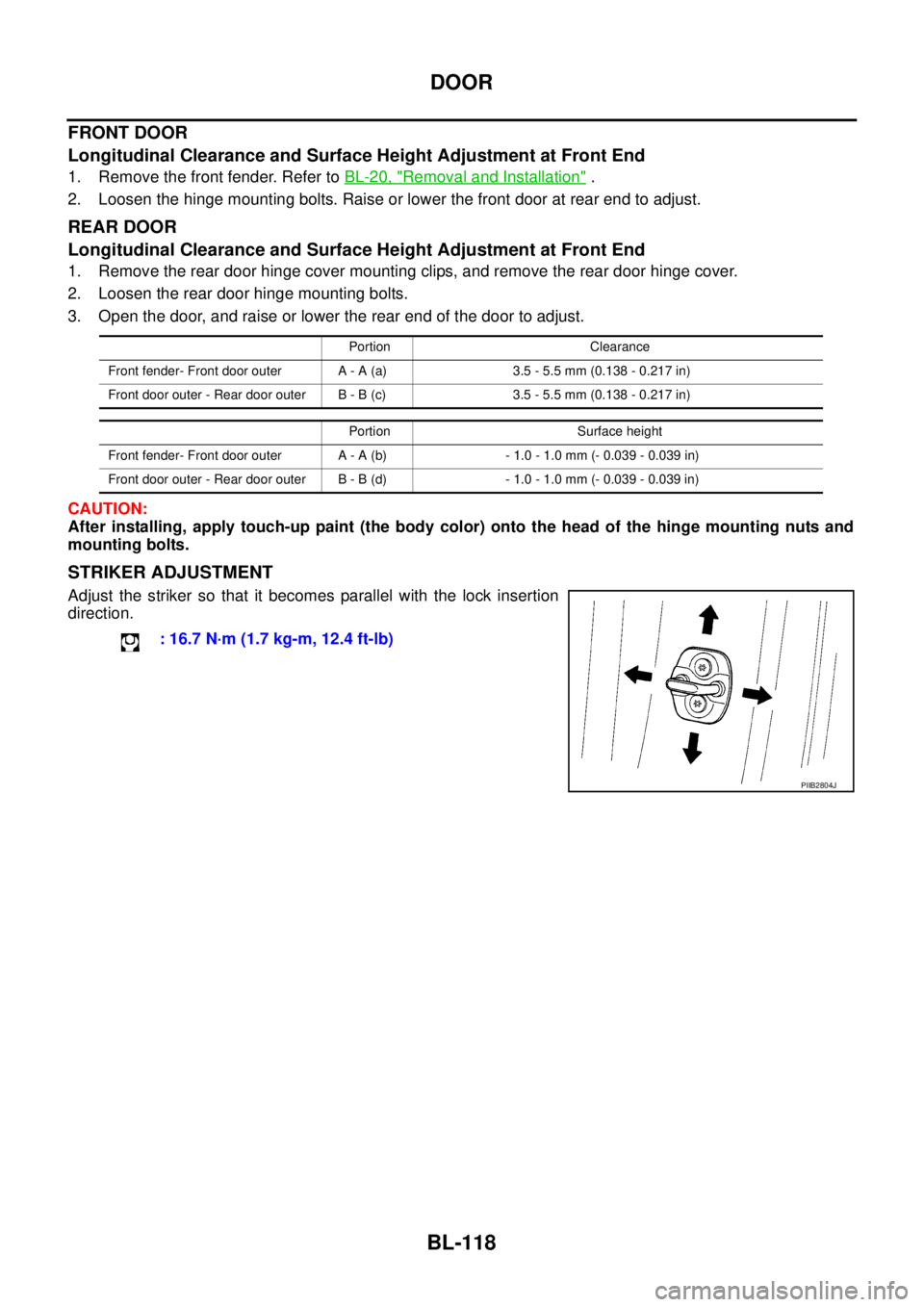
FRONT DOOR
Longitudinal Clearance and Surface Height Adjustment at Front End
1. Remove the front fender. Refer toBL-20, "Removal and Installation".
2. Loosen the hinge mounting bolts. Raise or lower the front door at rear end to adjust.
REAR DOOR
Longitudinal Clearance and Surface Height Adjustment at Front End
1. Remove the rear door hinge cover mounting clips, and remove the rear door hinge cover.
2. Loosen the rear door hinge mounting bolts.
3. Open the door, and raise or lower the rear end of the door to adjust.
CAUTION:
After installing, apply touch-up paint (the body color) onto the head of the hinge mounting nuts and
mounting bolts.
STRIKER ADJUSTMENT
Adjust the striker so that it becomes parallel with the lock insertion
direction.
Portion Clearance
Front fender- Front door outer A - A (a) 3.5 - 5.5 mm (0.138 - 0.217 in)
Front door outer - Rear door outer B - B (c) 3.5 - 5.5 mm (0.138 - 0.217 in)
Portion Surface height
Front fender- Front door outer A - A (b) - 1.0 - 1.0 mm (- 0.039 - 0.039 in)
Front door outer - Rear door outer B - B (d) - 1.0 - 1.0 mm (- 0.039 - 0.039 in)
: 16.7 N·m (1.7 kg-m, 12.4 ft-lb)
PIIB2804J
Page 703 of 3171
DOOR
BL-119
C
D
E
F
G
H
J
K
L
MA
B
BL
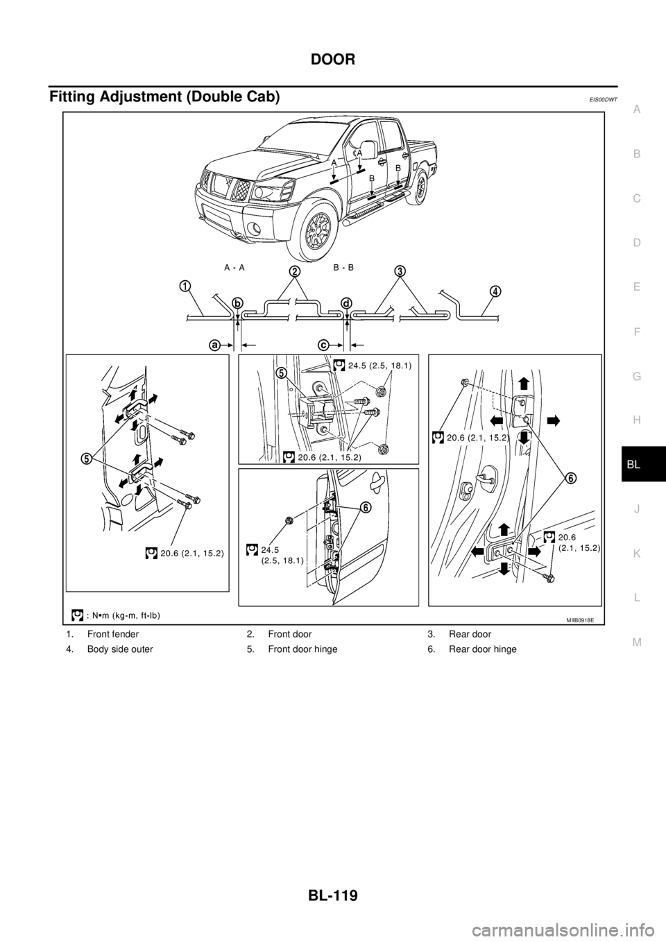
Fitting Adjustment (Double Cab)EIS00DWT
1. Front fender 2. Front door 3. Rear door
4. Body side outer 5. Front door hinge 6. Rear door hinge
MIIB0918E
Page 704 of 3171
BL-120
DOOR
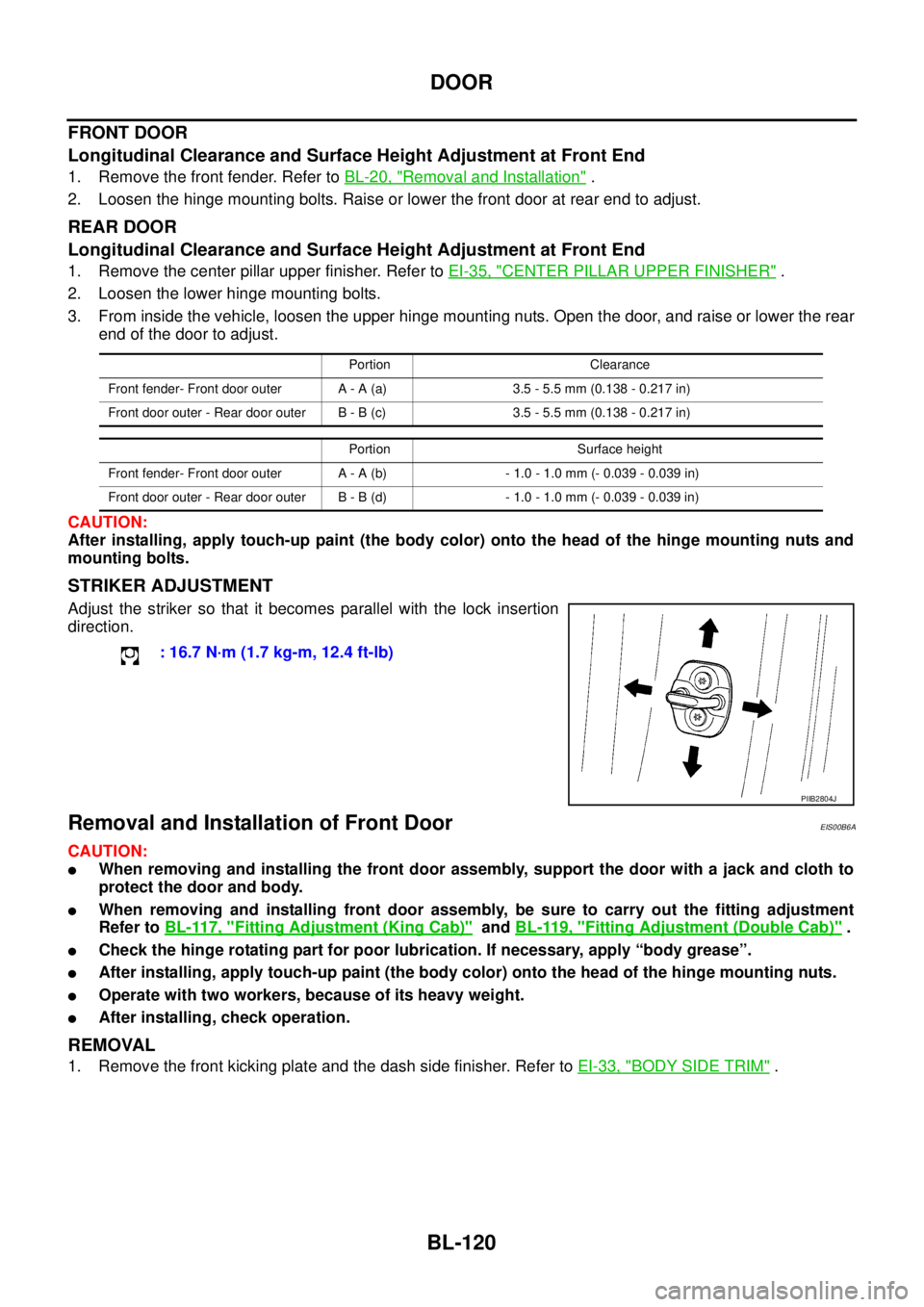
FRONT DOOR
Longitudinal Clearance and Surface Height Adjustment at Front End
1. Remove the front fender. Refer toBL-20, "Removal and Installation".
2. Loosen the hinge mounting bolts. Raise or lower the front door at rear end to adjust.
REAR DOOR
Longitudinal Clearance and Surface Height Adjustment at Front End
1. Remove the center pillar upper finisher. Refer toEI-35, "CENTER PILLAR UPPER FINISHER".
2. Loosen the lower hinge mounting bolts.
3. From inside the vehicle, loosen the upper hinge mounting nuts. Open the door, and raise or lower the rear
end of the door to adjust.
CAUTION:
After installing, apply touch-up paint (the body color) onto the head of the hinge mounting nuts and
mounting bolts.
STRIKER ADJUSTMENT
Adjust the striker so that it becomes parallel with the lock insertion
direction.
Removal and Installation of Front DoorEIS00B6A
CAUTION:
lWhen removing and installing the front door assembly, support the door with a jack and cloth to
protect the door and body.
lWhen removing and installing front door assembly, be sure to carry out the fitting adjustment
Refer toBL-117, "
Fitting Adjustment (King Cab)"andBL-119, "Fitting Adjustment (Double Cab)".
lCheck the hinge rotating part for poor lubrication. If necessary, apply “body grease”.
lAfter installing, apply touch-up paint (the body color) onto the head of the hinge mounting nuts.
lOperate with two workers, because of its heavy weight.
lAfter installing, check operation.
REMOVAL
1. Remove the front kicking plate and the dash side finisher. Refer toEI-33, "BODY SIDE TRIM".
Portion Clearance
Front fender- Front door outer A - A (a) 3.5 - 5.5 mm (0.138 - 0.217 in)
Front door outer - Rear door outer B - B (c) 3.5 - 5.5 mm (0.138 - 0.217 in)
Portion Surface height
Front fender- Front door outer A - A (b) - 1.0 - 1.0 mm (- 0.039 - 0.039 in)
Front door outer - Rear door outer B - B (d) - 1.0 - 1.0 mm (- 0.039 - 0.039 in)
: 16.7 N·m (1.7 kg-m, 12.4 ft-lb)
PIIB2804J
Page 705 of 3171
DOOR
BL-121
C
D
E
F
G
H
J
K
L
MA
B
BL
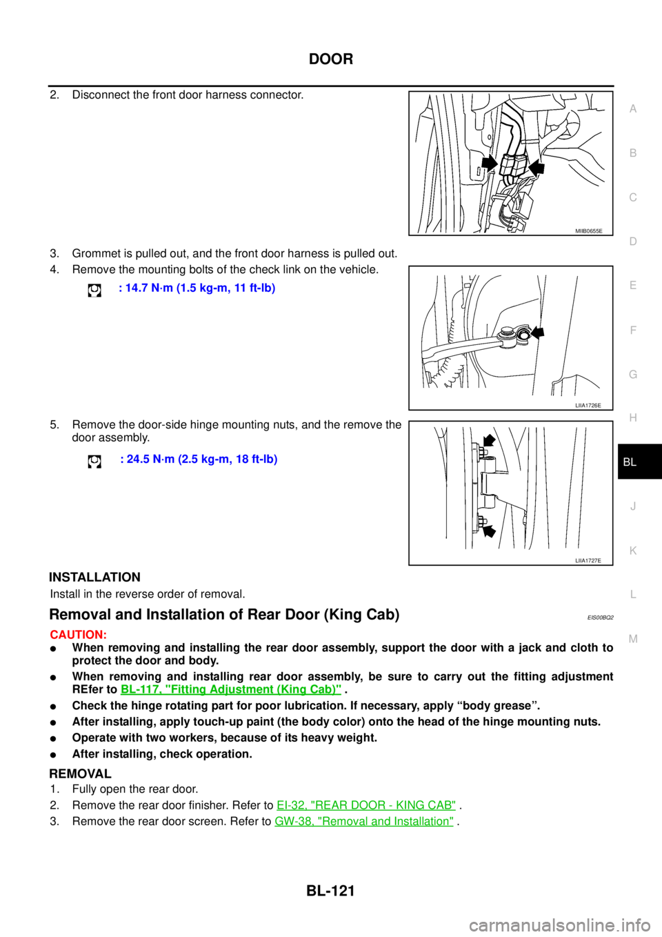
2. Disconnect the front door harness connector.
3. Grommet is pulled out, and the front door harness is pulled out.
4. Remove the mounting bolts of the check link on the vehicle.
5. Remove the door-side hinge mounting nuts, and the remove the
door assembly.
INSTALLATION
Install in the reverse order of removal.
Removal and Installation of Rear Door (King Cab)EIS00BQ2
CAUTION:
lWhen removing and installing the rear door assembly, support the door with a jack and cloth to
protect the door and body.
lWhen removing and installing rear door assembly, be sure to carry out the fitting adjustment
REfer toBL-117, "
Fitting Adjustment (King Cab)".
lCheck the hinge rotating part for poor lubrication. If necessary, apply “body grease”.
lAfter installing, apply touch-up paint (the body color) onto the head of the hinge mounting nuts.
lOperate with two workers, because of its heavy weight.
lAfter installing, check operation.
REMOVAL
1. Fully open the rear door.
2. Remove the rear door finisher. Refer toEI-32, "
REAR DOOR - KING CAB".
3. Remove the rear door screen. Refer toGW-38, "
Removal and Installation".
MIIB0655E
: 14.7 N·m (1.5 kg-m, 11 ft-lb)
LIIA1726E
: 24.5 N·m (2.5 kg-m, 18 ft-lb)
LIIA1727E
Page 706 of 3171
BL-122
DOOR
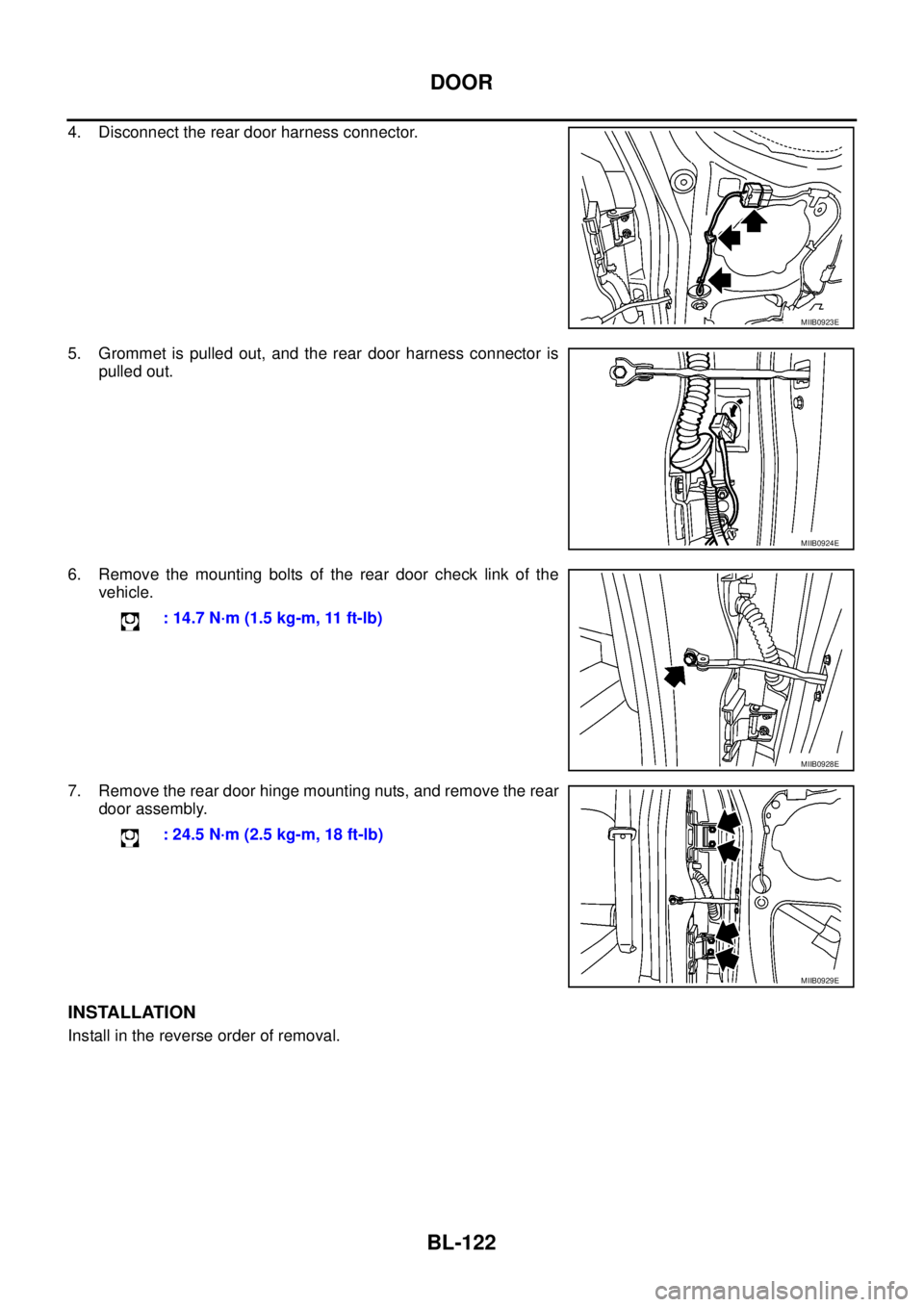
4. Disconnect the rear door harness connector.
5. Grommet is pulled out, and the rear door harness connector is
pulled out.
6. Remove the mounting bolts of the rear door check link of the
vehicle.
7. Remove the rear door hinge mounting nuts, and remove the rear
door assembly.
INSTALLATION
Install in the reverse order of removal.
MIIB0923E
MIIB0924E
: 14.7 N·m (1.5 kg-m, 11 ft-lb)
MIIB0928E
: 24.5 N·m (2.5 kg-m, 18 ft-lb)
MIIB0929E
Page 707 of 3171
DOOR
BL-123
C
D
E
F
G
H
J
K
L
MA
B
BL
Removal and Installation of Rear Door (Double Cab)EIS00DUN
CAUTION:
lWhen removing and installing the rear door assembly, support the door with a jack and cloth to
protect the door and body.
lWhen removing and installing rear door assembly, be sure to carry out the fitting adjustment
REfer toBL-119, "
Fitting Adjustment (Double Cab)".
lCheck the hinge rotating part for poor lubrication. If necessary, apply “body grease”.
lAfter installing, apply touch-up paint (the body color) onto the head of the hinge mounting nuts.
lOperate with two workers, because of its heavy weight.
lAfter installing, check operation.
REMOVAL
1. Remove the center pillar lower finisher. Refer toEI-33, "BODY SIDE TRIM".
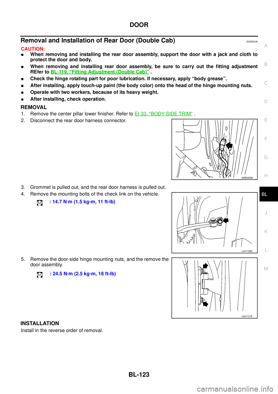
2. Disconnect the rear door harness connector.
3. Grommet is pulled out, and the rear door harness is pulled out.
4. Remove the mounting bolts of the check link on the vehicle.
5. Remove the door-side hinge mounting nuts, and the remove the
door assembly.
INSTALLATION
Install in the reverse order of removal.
MIIB0656E
: 14.7 N·m (1.5 kg-m, 11 ft-lb)
LIIA1726E
: 24.5 N·m (2.5 kg-m, 18 ft-lb)
LIIA1727E
Page 708 of 3171

BL-124
DOOR
Removal and Installation of Door Weather-strip (King Cab)
EIS00BQ6
REMOVAL
CAUTION:
After removal, do not pull strongly on the weather-strip.
Remove the weather-strip clips, and remove weather strip.
INSTALLATION
Install in the reverse order of removal.
1. Front door outer 2. Front door weather-strip 3. Rear door outer
4. Rear door weather-strip 5. Sill outer 6. Body side outer
MIIB0921E
Page 709 of 3171
DOOR
BL-125
C
D
E
F
G
H
J
K
L
MA
B
BL
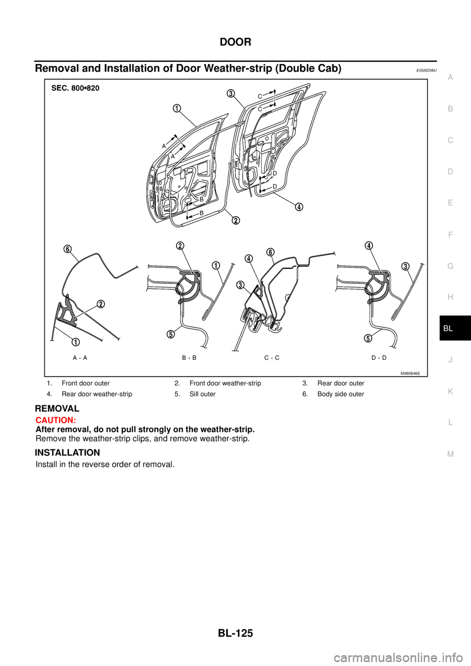
Removal and Installation of Door Weather-strip (Double Cab)EIS00DWU
REMOVAL
CAUTION:
After removal, do not pull strongly on the weather-strip.
Remove the weather-strip clips, and remove weather-strip.
INSTALLATION
Install in the reverse order of removal.
1. Front door outer 2. Front door weather-strip 3. Rear door outer
4. Rear door weather-strip 5. Sill outer 6. Body side outer
MIIB0646E
Page 710 of 3171
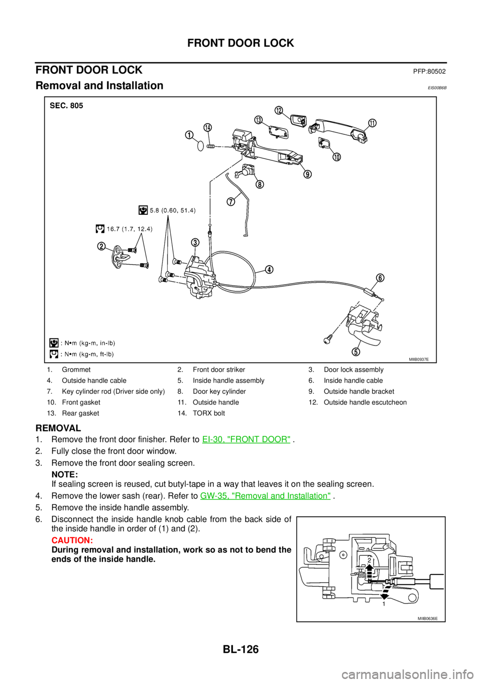
BL-126
FRONT DOOR LOCK
FRONT DOOR LOCK
PFP:80502
Removal and InstallationEIS00B6B
REMOVAL
1. Remove the front door finisher. Refer toEI-30, "FRONT DOOR".
2. Fully close the front door window.
3. Remove the front door sealing screen.
NOTE:
If sealing screen is reused, cut butyl-tape in a way that leaves it on the sealing screen.
4. Remove the lower sash (rear). Refer toGW-35, "
Removal and Installation".
5. Remove the inside handle assembly.
6. Disconnect the inside handle knob cable from the back side of
the inside handle in order of (1) and (2).
CAUTION:
During removal and installation, work so as not to bend the
ends of the inside handle.
1. Grommet 2. Front door striker 3. Door lock assembly
4. Outside handle cable 5. Inside handle assembly 6. Inside handle cable
7. Key cylinder rod (Driver side only) 8. Door key cylinder 9. Outside handle bracket
10. Front gasket 11. Outside handle 12. Outside handle escutcheon
13. Rear gasket 14. TORX bolt
MIIB0937E
MIIB0636E