NISSAN NAVARA 2005 Repair Workshop Manual
Manufacturer: NISSAN, Model Year: 2005, Model line: NAVARA, Model: NISSAN NAVARA 2005Pages: 3171, PDF Size: 49.59 MB
Page 691 of 3171
MULTI-REMOTE CONTROL SYSTEM
BL-107
C
D
E
F
G
H
J
K
L
MA
B
BL
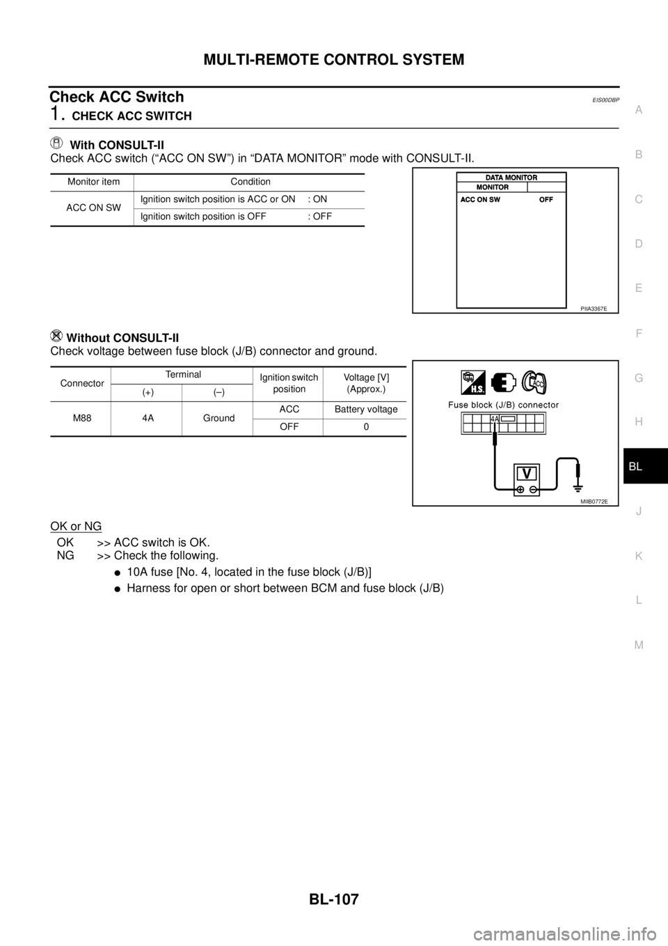
Check ACC SwitchEIS00DBP
1.CHECK ACC SWITCH
With CONSULT-II
Check ACC switch (“ACC ON SW”) in “DATA MONITOR” mode with CONSULT-II.
Without CONSULT-II
Check voltage between fuse block (J/B) connector and ground.
OK or NG
OK >> ACC switch is OK.
NG >> Check the following.
l10A fuse [No. 4, located in the fuse block (J/B)]
lHarness for open or short between BCM and fuse block (J/B)
Monitor item Condition
ACC ON SWIgnition switch position is ACC or ON : ON
Ignition switch position is OFF : OFF
PIIA3367E
ConnectorTerminal
Ignition switch
positionVoltage [V]
(Approx.)
(+) (–)
M88 4A GroundACC Battery voltage
OFF 0
MIIB0772E
Page 692 of 3171
BL-108
MULTI-REMOTE CONTROL SYSTEM
Check Door Switch
EIS00DBQ
CHECK DOOR SWITCH (DOUBLE CAB)
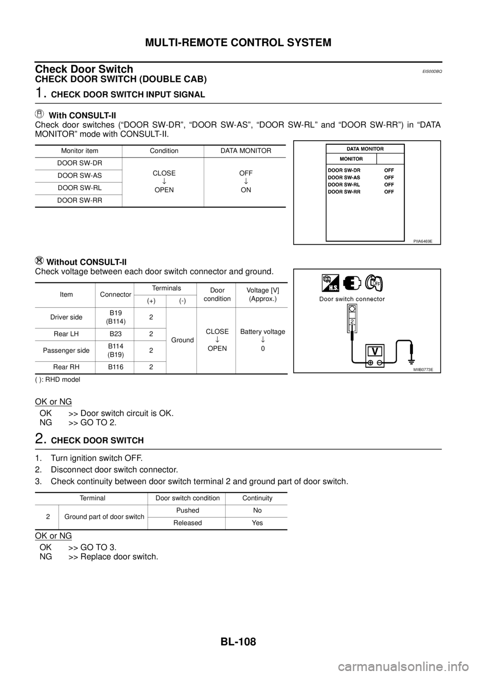
1.CHECK DOOR SWITCH INPUT SIGNAL
With CONSULT-II
Check door switches (“DOOR SW-DR”, “DOOR SW-AS”, “DOOR SW-RL” and “DOOR SW-RR”) in “DATA
MONITOR” mode with CONSULT-II.
Without CONSULT-II
Check voltage between each door switch connector and ground.
( ): RHD model
OK or NG
OK >> Door switch circuit is OK.
NG >> GO TO 2.
2.CHECK DOOR SWITCH
1. Turn ignition switch OFF.
2. Disconnect door switch connector.
3. Check continuity between door switch terminal 2 and ground part of door switch.
OK or NG
OK >> GO TO 3.
NG >> Replace door switch.
Monitor item Condition DATA MONITOR
DOOR SW-DR
CLOSE
ÂŻ
OPENOFF
ÂŻ
ON DOOR SW-AS
DOOR SW-RL
DOOR SW-RR
PIIA6469E
Item ConnectorTerminals
Door
conditionVoltage [V]
(Approx.)
(+) (-)
Driver sideB19
(B114)2
GroundCLOSE
ÂŻ
OPENBattery voltage
ÂŻ
0 Rear LH B23 2
Passenger sideB114
(B19)2
Rear RH B116 2
MIIB0773E
Terminal Door switch condition Continuity
2 Ground part of door switchPushed No
Released Yes
Page 693 of 3171
MULTI-REMOTE CONTROL SYSTEM
BL-109
C
D
E
F
G
H
J
K
L
MA
B
BL
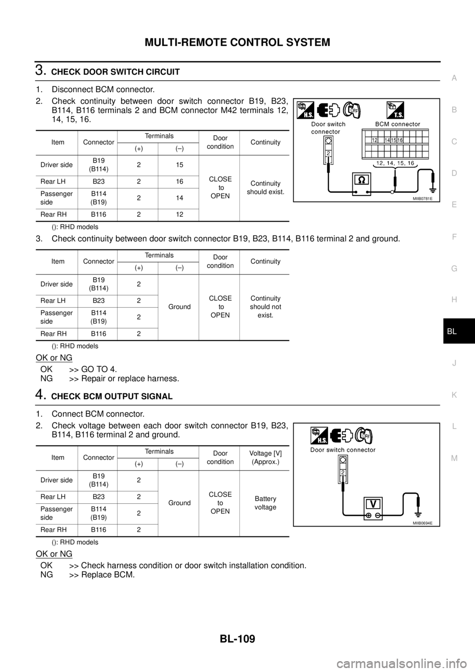
3.CHECK DOOR SWITCH CIRCUIT
1. Disconnect BCM connector.
2. Check continuity between door switch connector B19, B23,
B114, B116 terminals 2 and BCM connector M42 terminals 12,
14, 15, 16.
(): RHD models
3. Check continuity between door switch connector B19, B23, B114, B116 terminal 2 and ground.
(): RHD models
OK or NG
OK >> GO TO 4.
NG >> Repair or replace harness.
4.CHECK BCM OUTPUT SIGNAL
1. Connect BCM connector.
2. Check voltage between each door switch connector B19, B23,
B114, B116 terminal 2 and ground.
(): RHD models
OK or NG
OK >> Check harness condition or door switch installation condition.
NG >> Replace BCM.
Item ConnectorTerminals
Door
conditionContinuity
(+) (–)
Driver sideB19
(B114)215
CLOSE
to
OPENContinuity
should exist. Rear LH B23 2 16
Passenger
sideB114
(B19)214
Rear RH B116 2 12
Item ConnectorTerminals
Door
conditionContinuity
(+) (–)
Driver sideB19
(B114)2
GroundCLOSE
to
OPENContinuity
should not
exist. Rear LH B23 2
Passenger
sideB114
(B19)2
Rear RH B116 2
MIIB0781E
Item ConnectorTerminals
Door
conditionVoltag e [V]
(Approx.)
(+) (–)
Driver sideB19
(B114)2
GroundCLOSE
to
OPENBattery
voltage Rear LH B23 2
Passenger
sideB114
(B19)2
Rear RH B116 2
MIIB0694E
Page 694 of 3171
BL-110
MULTI-REMOTE CONTROL SYSTEM
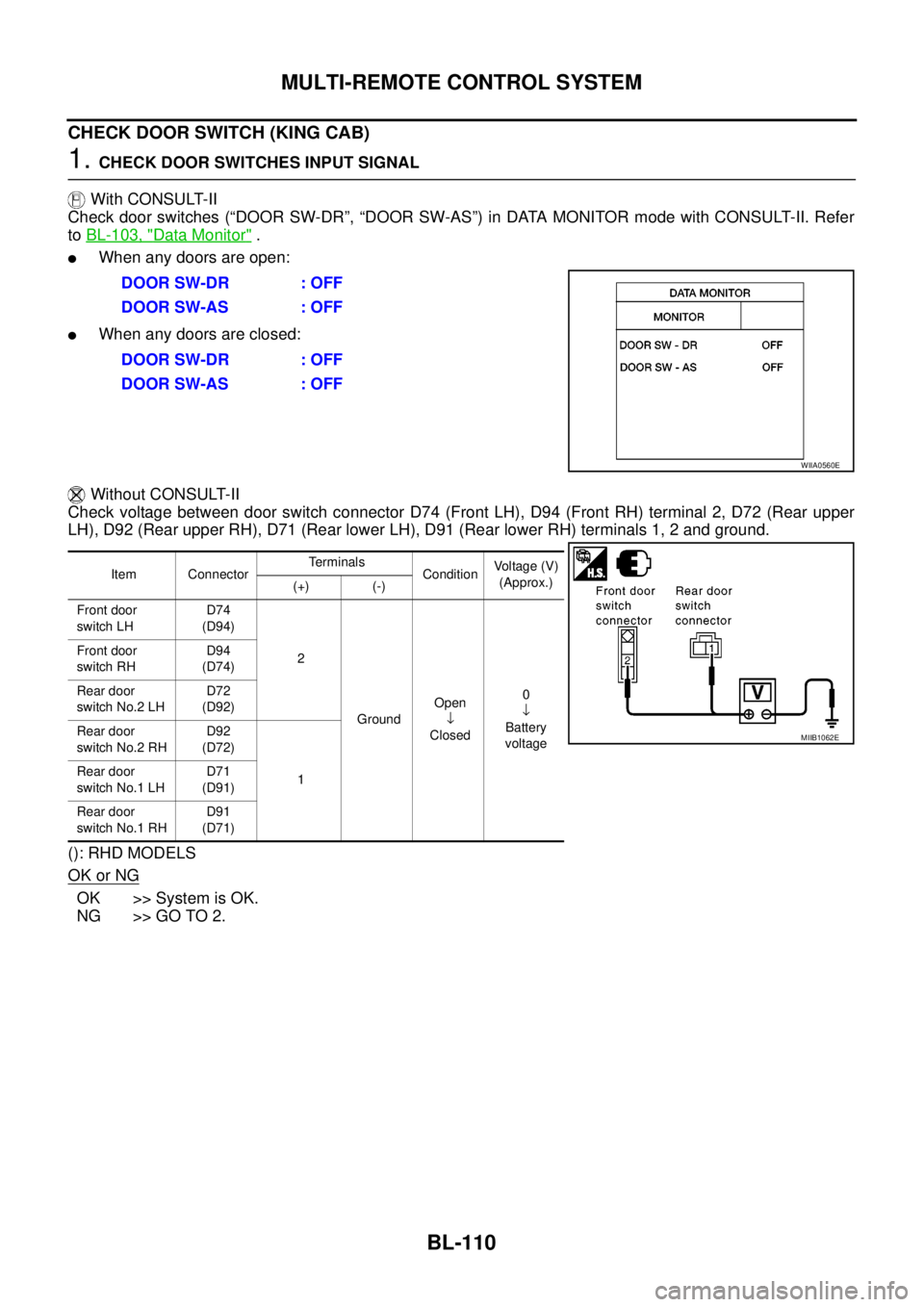
CHECK DOOR SWITCH (KING CAB)
1.CHECK DOOR SWITCHES INPUT SIGNAL
With CONSULT-II
Check door switches (“DOOR SW-DR”, “DOOR SW-AS”) in DATA MONITOR mode with CONSULT-II. Refer
toBL-103, "
Data Monitor".
lWhen any doors are open:
lWhen any doors are closed:
Without CONSULT-II
Check voltage between door switch connector D74 (Front LH), D94 (Front RH) terminal 2, D72 (Rear upper
LH), D92 (Rear upper RH), D71 (Rear lower LH), D91 (Rear lower RH) terminals 1, 2 and ground.
(): RHD MODELS
OK or NG
OK >> System is OK.
NG >> GO TO 2.DOOR SW-DR : OFF
DOOR SW-AS : OFF
DOOR SW-DR : OFF
DOOR SW-AS : OFF
WIIA0560E
Item ConnectorTerminals
ConditionVoltage (V)
(Approx.)
(+) (-)
Front door
switch LHD74
(D94)
2
GroundOpen
ÂŻ
Closed0
ÂŻ
Battery
voltage Front door
switch RHD94
(D74)
Rear door
switch No.2 LHD72
(D92)
Rear door
switch No.2 RHD92
(D72)
1 Rear door
switch No.1 LHD71
(D91)
Rear door
switch No.1 RHD91
(D71)
MIIB1062E
Page 695 of 3171

MULTI-REMOTE CONTROL SYSTEM
BL-111
C
D
E
F
G
H
J
K
L
MA
B
BL
2.CHECK DOOR SWITCH CIRCUIT
1. Turn ignition switch OFF.
2. Disconnect door switch and BCM.
3. Check continuity between door switch connector D74 (Front LH), D94 (Front RH) terminal 2, D72 (Rear
upper LH), D92 (Rear upper RH), D71 (Rear lower LH), D91 (Rear lower RH) terminal 1 and BCM con-
nector M42 terminals 14, and 15.
(): RHD MODELS
OK or NG
OK >> GO TO 3.
NG >> Repair or replace harness.
3.CHECK DOOR SWITCHES
Check continuity between door switch terminals.
OK or NG
OK >> GO TO 4.
NG >> Replace door switch.
Connector Terminals Item Connector Terminals Condition
M4215Front door
switch LHD74
(D94)2
Continuity
should exist 14Front door
switch RHD94
(D74)2
15Rear door
switch No. 2 LHD72
(D92)1
14Rear door
switch No. 2 RHD92
(D72)1
15Rear door
switch No. 1 LHD71
(D91)1
14Rear door
switch No. 1 RHD91
(D71)1
MIIB1063E
Item Terminals Condition Continuity
Door switches
(front)2-3Open Yes
Closed No
Door switches
(rear upper and lower)1-2Open Yes
Closed No
MIIB1064E
Page 696 of 3171
BL-112
MULTI-REMOTE CONTROL SYSTEM
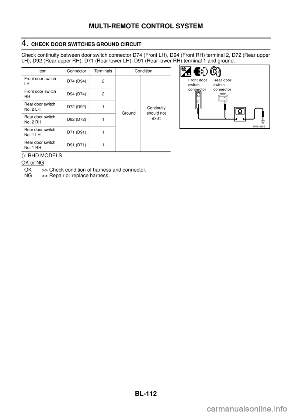
4.CHECK DOOR SWITCHES GROUND CIRCUIT
Check continuity between door switch connector D74 (Front LH), D94 (Front RH) terminal 2, D72 (Rear upper
LH), D92 (Rear upper RH), D71 (Rear lower LH), D91 (Rear lower RH) terminal 1 and ground.
(): RHD MODELS
OK or NG
OK >> Check condition of harness and connector.
NG >> Repair or replace harness.
Item Connector Terminals Condition
Front door switch
LHD74 (D94) 2
GroundContinuity
should not
exist Front door switch
RHD94 (D74) 2
Rear door switch
No. 2 LHD72 (D92) 1
Rear door switch
No. 2 RHD92 (D72) 1
Rear door switch
No. 1 LHD71 (D91) 1
Rear door switch
No. 1 RHD91 (D71) 1
MIIB1065E
Page 697 of 3171
MULTI-REMOTE CONTROL SYSTEM
BL-113
C
D
E
F
G
H
J
K
L
MA
B
BL
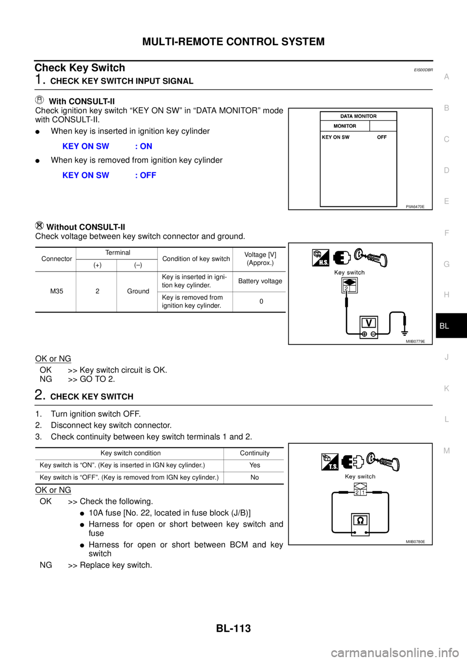
Check Key SwitchEIS00DBR
1.CHECK KEY SWITCH INPUT SIGNAL
With CONSULT-II
Check ignition key switch “KEY ON SW” in “DATA MONITOR” mode
with CONSULT-II.
lWhen key is inserted in ignition key cylinder
lWhen key is removed from ignition key cylinder
Without CONSULT-II
Check voltage between key switch connector and ground.
OK or NG
OK >> Key switch circuit is OK.
NG >> GO TO 2.
2.CHECK KEY SWITCH
1. Turn ignition switch OFF.
2. Disconnect key switch connector.
3. Check continuity between key switch terminals 1 and 2.
OK or NG
OK >> Check the following.
l10Afuse[No.22,locatedinfuseblock(J/B)]
lHarness for open or short between key switch and
fuse
lHarness for open or short between BCM and key
switch
NG >> Replace key switch.KEY ON SW : ON
KEY ON SW : OFF
PIIA6470E
ConnectorTerminal
Condition of key switchVo l ta g e [V ]
(Approx.)
(+) (–)
M35 2 GroundKey is inserted in igni-
tion key cylinder.Battery voltage
Key is removed from
ignition key cylinder.0
MIIB0779E
Key switch condition Continuity
Key switch is “ON”. (Key is inserted in IGN key cylinder.) Yes
Key switch is “OFF”. (Key is removed from IGN key cylinder.) No
MIIB0780E
Page 698 of 3171

BL-114
MULTI-REMOTE CONTROL SYSTEM
Check Hazard Function
EIS00DBS
1.CHECK HAZARD WARNING LAMP
Doeshazardwarninglampflashwhilehazardswitchispressed?
YESorNO
YES >> Hazard warning lamp circuit is OK.
NO >> Check hazard circuit. Refer toLT-97, "
TURN SIGNAL AND HAZARD WARNING LAMPS".
Check Map Lamp and Ignition Keyhole Illumination FunctionEIS00DBT
1.CHECK MAP LAMP AND IGNITION KEYHOLE ILLUMINATION FUNCTION
When map lamp switch is in “DOOR” position, open the front door (LH or RH).
OK or NG
OK >> Map lamp and ignition switch key hole illumination circuit is OK.
NG >> Check ignition illumination circuit. Refer toLT- 1 4 5 , "
INTERIOR ROOM LAMP". Map lamp and ignition keyhole illumination should illuminate.
Page 699 of 3171

MULTI-REMOTE CONTROL SYSTEM
BL-115
C
D
E
F
G
H
J
K
L
MA
B
BL
ID Code Entry ProcedureEIS00DBU
KEYFOB ID SET UP
NOTE:
Keyfob ID setup procedure is same as ignition key registration (NATS initialization) procedure.
When the registration of the ignition key (NATS initialization) is performed with a NATS program card,
the registration of keyfob ID is done at the same time.
Regarding the procedures of NATS initialization and ignition key ID registration, refer to CONSULT-II
operation manual, NATS.
If additional key or key replacement is demanded, request all registed key fobs to be brought to the
dealer.
During the NATS initialization process, all registered key IDs will be deleted, thus, it is necessary to re-
register all keys.
CONSULT-II INSPECTION PROCEDURE
1. Turn ignition switch OFF.
2. Insert NATS program card into CONSULT-II.
3. Connect CONSULT-II and CONSULT-II CONVERTER to data
link connector.
4. Turn ignition switch ON.
5. Touch “START”.
6. Touch “OTHER”.Program card : NATS (AEN04A-1)
BBIA0538E
PBR455D
PIIB0900E
Page 700 of 3171
BL-116
MULTI-REMOTE CONTROL SYSTEM
7. Select “NATS V.5.0”.
If “NATS V5.0” is not indicated, go toGI-50, "
CONSULT-II Data
Link Connector (DLC) Circuit".
8. Perform each diagnostic test mode according to each service
procedure.
For further information, see the CONSULT-II Operation Manual
NATS.
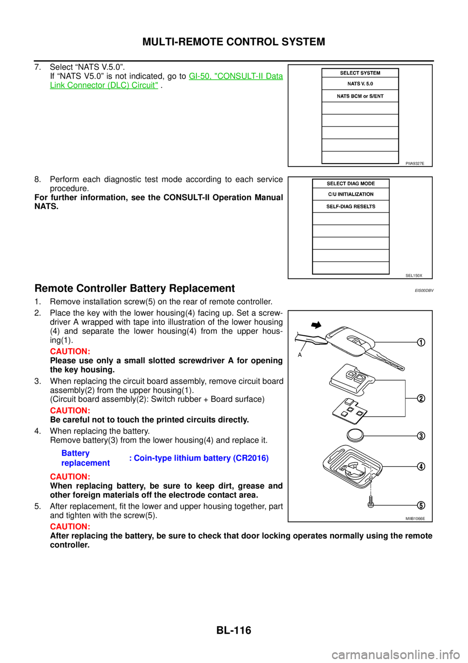
Remote Controller Battery ReplacementEIS00DBV
1. Remove installation screw(5) on the rear of remote controller.
2. Place the key with the lower housing(4) facing up. Set a screw-
driver A wrapped with tape into illustration of the lower housing
(4) and separate the lower housing(4) from the upper hous-
ing(1).
CAUTION:
Please use only a small slotted screwdriver A for opening
the key housing.
3. When replacing the circuit board assembly, remove circuit board
assembly(2) from the upper housing(1).
(Circuit board assembly(2): Switch rubber + Board surface)
CAUTION:
Be careful not to touch the printed circuits directly.
4. When replacing the battery.
Remove battery(3) from the lower housing(4) and replace it.
CAUTION:
When replacing battery, be sure to keep dirt, grease and
other foreign materials off the electrode contact area.
5. After replacement, fit the lower and upper housing together, part
and tighten with the screw(5).
CAUTION:
After replacing the battery, be sure to check that door locking operates normally using the remote
controller.
PIIA9327E
SEL150X
Battery
replacement: Coin-type lithium battery (CR2016)
MIIB1066E