NISSAN NOTE 2016 Service Repair Manual
Manufacturer: NISSAN, Model Year: 2016,
Model line: NOTE,
Model: NISSAN NOTE 2016
Pages: 3641, PDF Size: 28.72 MB
NISSAN NOTE 2016 Service Repair Manual
NOTE 2016
NISSAN
NISSAN
https://www.carmanualsonline.info/img/5/57363/w960_57363-0.png
NISSAN NOTE 2016 Service Repair Manual
Trending: roof, washer fluid, alternator, park assist, tire pressure, fuse diagram, key battery
Page 1801 of 3641
EXT-34
< REMOVAL AND INSTALLATION >
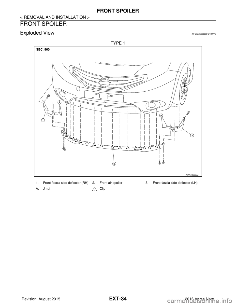
FRONT SPOILER
FRONT SPOILER
Exploded ViewINFOID:0000000012432173
TYPE 1
AWKIA2566ZZ
1. Front fascia side deflector (RH) 2. Front air spoiler3. Front fascia side deflector (LH)
A. J nut Clip
Revision: August 2015 2016 Versa Note
cardiagn.com
Page 1802 of 3641
FRONT SPOILEREXT-35
< REMOVAL AND INSTALLATION >
C
DE
F
G H
I
J
L
M A
B
EXT
N
O P
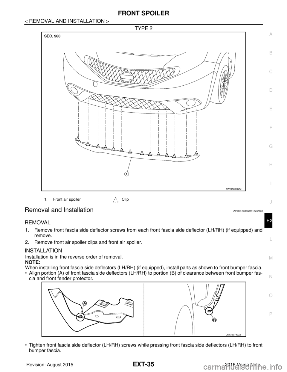
TYPE 2
Removal and InstallationINFOID:0000000012432174
REMOVAL
1. Remove front fascia side deflector screws from each front fascia side deflector (LH/RH) (if equipped) and
remove.
2. Remove front air spoiler clips and front air spoiler.
INSTALLATION
Installation is in the reverse order of removal.
NOTE:
When installing front fascia side deflectors (LH/RH) (if equipped), install parts as shown to front bumper fascia.
• Align portion (A) of front fascia side deflectors (LH/RH) to portion (B) of clearance between front bumper fas-
cia and front fender protector.
• Tighten front fascia side deflector (LH/RH) screws while pressing front fascia side deflectors (LH/RH) to front bumper fascia.
AWKIA3168ZZ
1. Front air spoiler Clip
JMKIB0740ZZ
Revision: August 2015 2016 Versa Note
cardiagn.com
Page 1803 of 3641
EXT-36
< REMOVAL AND INSTALLATION >
COWL TOP
COWL TOP
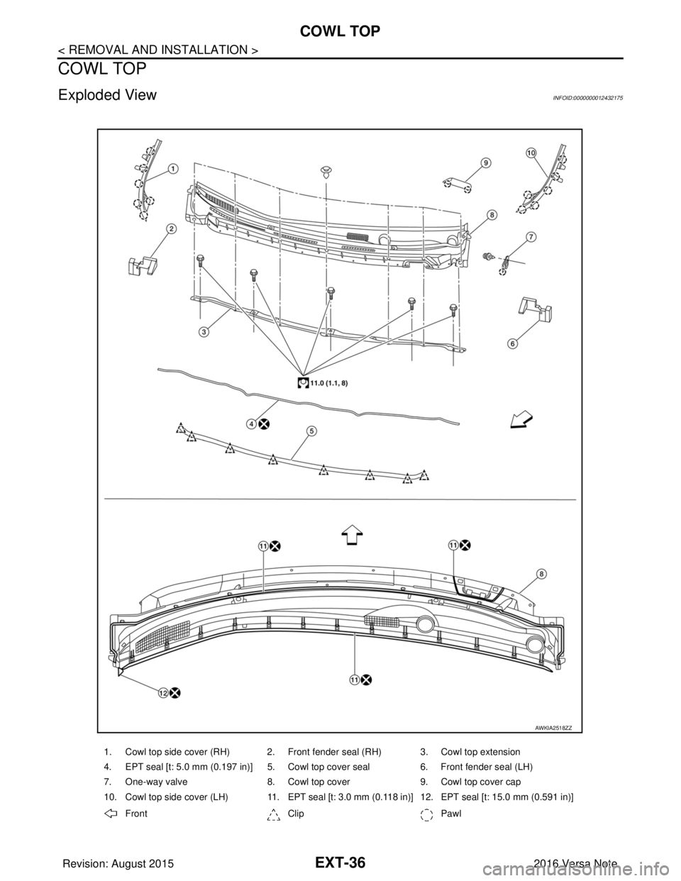
Exploded ViewINFOID:0000000012432175
1. Cowl top side cover (RH) 2. Front fender seal (RH) 3. Cowl top extension
4. EPT seal [t: 5.0 mm (0.197 in)] 5. Cowl top cover seal 6. Front fender seal (LH)
7. One-way valve 8. Cowl top cover 9. Cowl top cover cap
10. Cowl top side cover (LH) 11. EPT seal [t: 3.0 mm (0.118 in)] 12. EPT seal [t: 15.0 mm (0.591 in)]
Front ClipPawl
AWKIA2518ZZ
Revision: August 2015 2016 Versa Note
cardiagn.com
Page 1804 of 3641
COWL TOPEXT-37
< REMOVAL AND INSTALLATION >
C
DE
F
G H
I
J
L
M A
B
EXT
N
O P
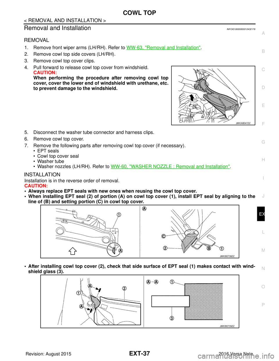
Removal and InstallationINFOID:0000000012432176
REMOVAL
1. Remove front wiper arms (LH/RH). Refer to WW-63, "Removal and Installation".
2. Remove cowl top side covers (LH/RH).
3. Remove cowl top cover clips.
4. Pull forward to release cowl top cover from windshield. CAUTION:
When performing the procedur e after removing cowl top
cover, cover the lower end of windshield with urethane, etc.
to prevent damage to the windshield.
5. Disconnect the washer tube connector and harness clips.
6. Remove cowl top cover.
7. Remove the following parts after removing cowl top cover (if necessary). • EPT seals
• Cowl top cover seal
• Washer tube
• Washer nozzles (LH/RH). Refer to WW-60, "
WASHER NOZZLE : Removal and Installation".
INSTALLATION
Installation is in the reverse order of removal.
CAUTION:
• Always replace EPT seals with new ones when reusing the cowl top cover.
• When installing EPT seal (2) of po rtion (A) on cowl top cover (1), install EPT seal by aligning to the
line of (B) and setting portion (C) in cowl top cover.
• After installing cowl top cover (2), check that side surface of EPT seal (1) makes contact with wind- shield glass (3).
JMKIA8047ZZ
JMKIB0738ZZ
JMKIB0739ZZ
Revision: August 2015 2016 Versa Note
cardiagn.com
Page 1805 of 3641
EXT-38
< REMOVAL AND INSTALLATION >
FENDER PROTECTOR
FENDER PROTECTOR
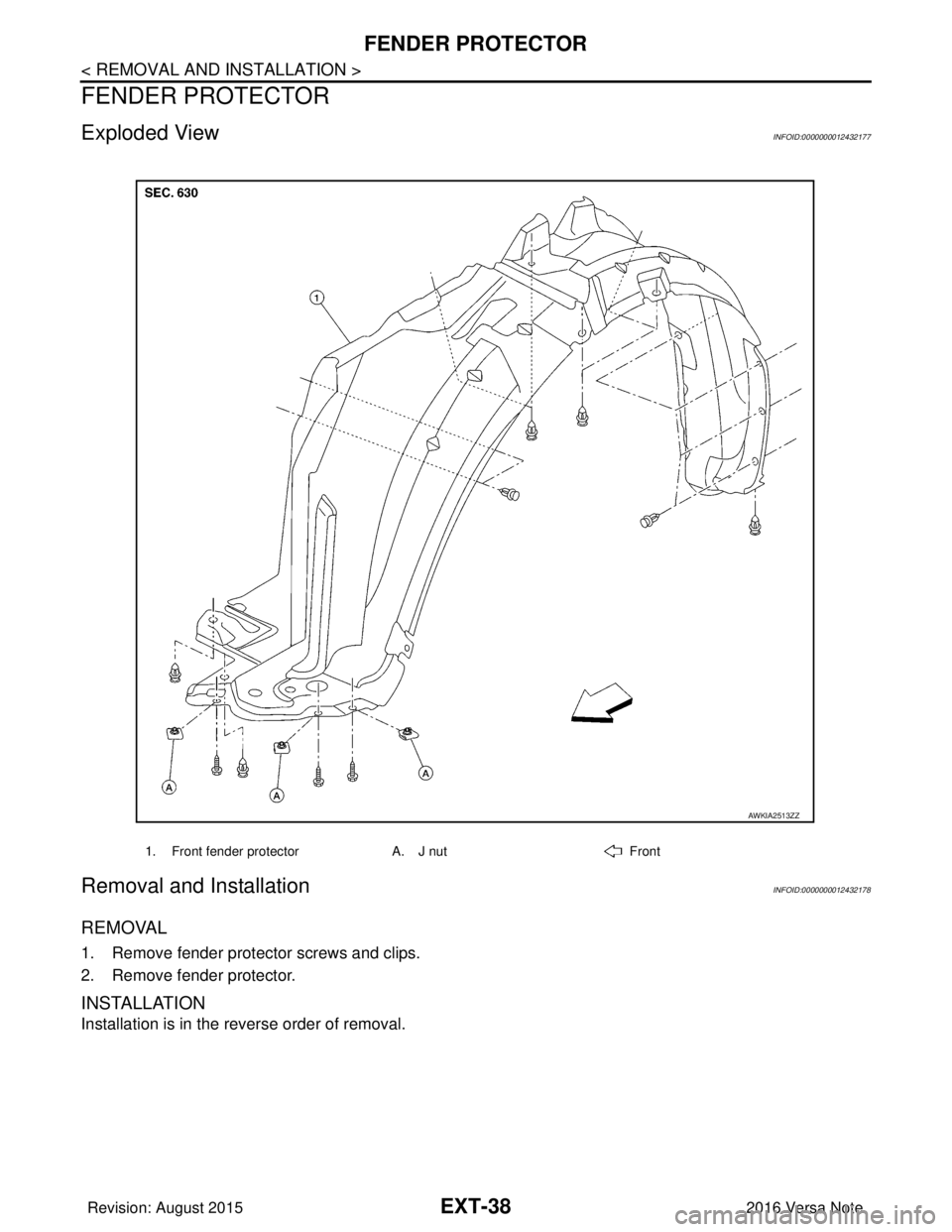
Exploded ViewINFOID:0000000012432177
Removal and InstallationINFOID:0000000012432178
REMOVAL
1. Remove fender protector screws and clips.
2. Remove fender protector.
INSTALLATION
Installation is in the reverse order of removal.
1. Front fender protectorA. J nutFront
AWKIA2513ZZ
Revision: August 2015 2016 Versa Note
cardiagn.com
Page 1806 of 3641
UNDER COVEREXT-39
< REMOVAL AND INSTALLATION >
C
DE
F
G H
I
J
L
M A
B
EXT
N
O P
UNDER COVER
FRONT UNDER COVER
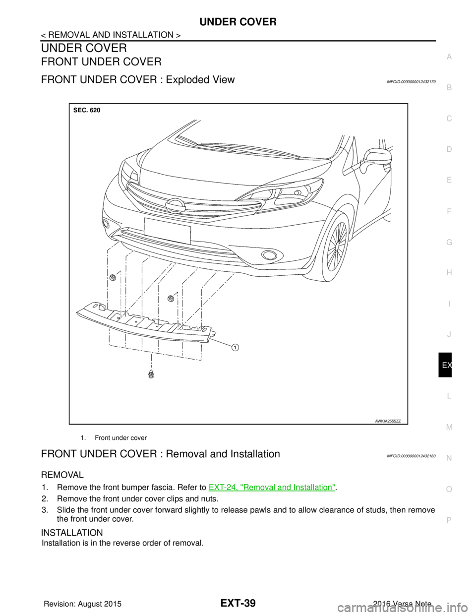
FRONT UNDER COVER : Exploded ViewINFOID:0000000012432179
FRONT UNDER COVER : Removal and InstallationINFOID:0000000012432180
REMOVAL
1. Remove the front bumper fascia. Refer to EXT-24, "Removal and Installation".
2. Remove the front under cover clips and nuts.
3. Slide the front under cover forward slightly to release pawls and to allow clearance of studs, then remove the front under cover.
INSTALLATION
Installation is in the reverse order of removal.
1. Front under cover
AWKIA2555ZZ
Revision: August 2015 2016 Versa Note
cardiagn.com
Page 1807 of 3641
EXT-40
< REMOVAL AND INSTALLATION >
UNDER COVER
Exploded View
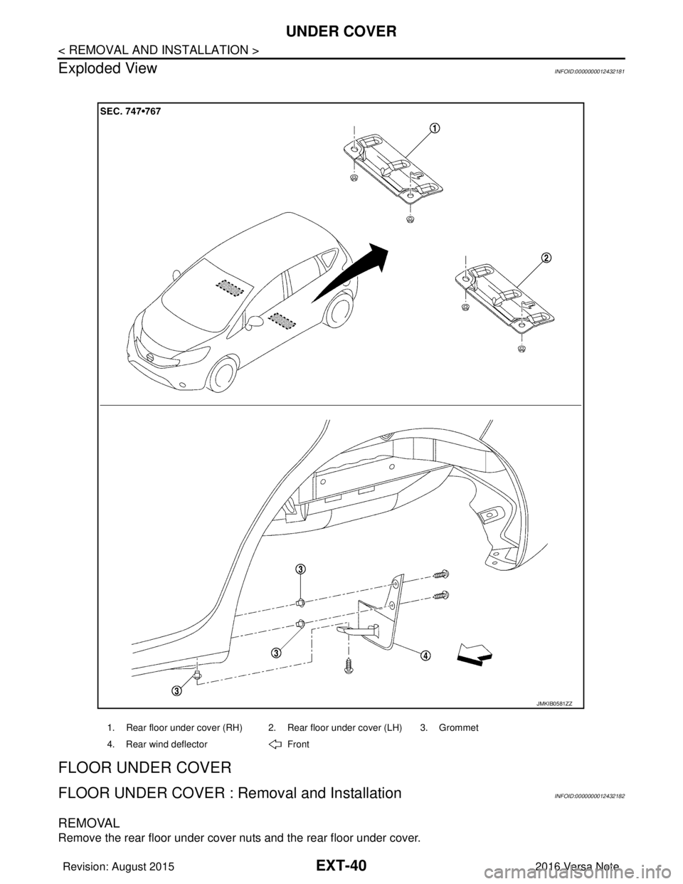
INFOID:0000000012432181
FLOOR UNDER COVER
FLOOR UNDER COVER : Removal and InstallationINFOID:0000000012432182
REMOVAL
Remove the rear floor under cover nuts and the rear floor under cover.
1. Rear floor under cover (RH) 2. Rear floor under cover (LH) 3. Grommet
4. Rear wind deflector Front
JMKIB0581ZZ
Revision: August 2015 2016 Versa Note
cardiagn.com
Page 1808 of 3641
UNDER COVEREXT-41
< REMOVAL AND INSTALLATION >
C
DE
F
G H
I
J
L
M A
B
EXT
N
O P
INSTALLATION
Installation is in the reverse order of removal.
REAR WIND DEFLECTOR
REAR WIND DEFLECTOR : Removal and InstallationINFOID:0000000012432183
REMOVAL
Remove the rear wind deflector screws and the rear wind deflector.
INSTALLATION
Installation is in the reverse order of removal.
Revision: August 2015 2016 Versa Note
cardiagn.com
Page 1809 of 3641
EXT-42
< REMOVAL AND INSTALLATION >
ROOF SIDE MOLDING
ROOF SIDE MOLDING
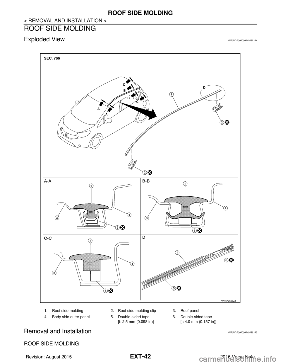
Exploded ViewINFOID:0000000012432184
Removal and InstallationINFOID:0000000012432185
ROOF SIDE MOLDING
1. Roof side molding2. Roof side molding clip 3. Roof panel
4. Body side outer panel 5. Double-sided tape
[t: 2.5 mm (0.098 in)] 6. Double-sided tape
[t: 4.0 mm (0.157 in)]
AWKIA2556ZZ
Revision: August 2015 2016 Versa Note
cardiagn.com
Page 1810 of 3641
ROOF SIDE MOLDINGEXT-43
< REMOVAL AND INSTALLATION >
C
DE
F
G H
I
J
L
M A
B
EXT
N
O P
Removal
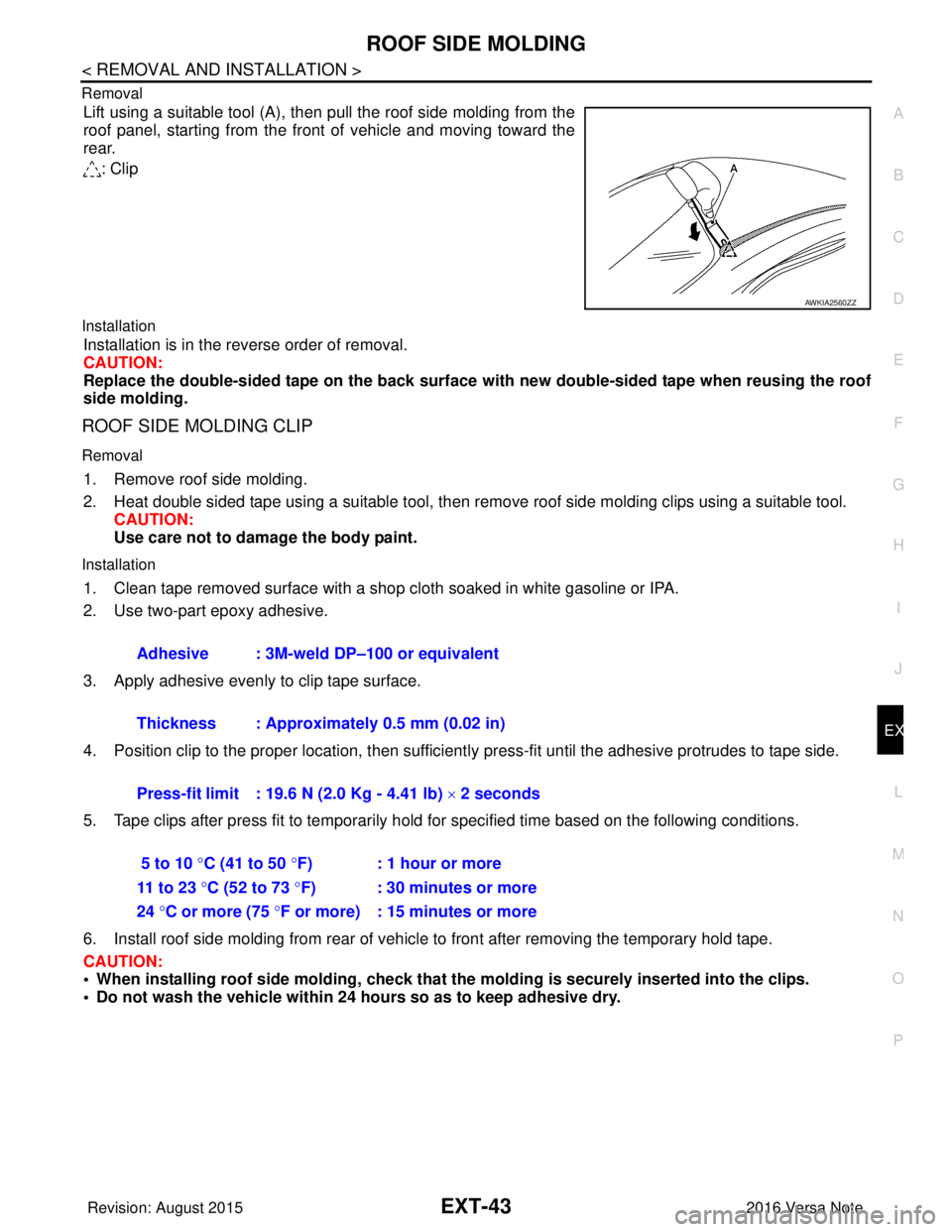
Lift using a suitable tool (A), then pull the roof side molding from the
roof panel, starting from the front of vehicle and moving toward the
rear.
: Clip
Installation
Installation is in the reverse order of removal.
CAUTION:
Replace the double-sided tape on the back surface with new double-sided tape when reusing the roof
side molding.
ROOF SIDE MOLDING CLIP
Removal
1. Remove roof side molding.
2. Heat double sided tape using a suitable tool, then remove roof side molding clips using a suitable tool.
CAUTION:
Use care not to damage the body paint.
Installation
1. Clean tape removed surface with a shop cloth soaked in white gasoline or IPA.
2. Use two-part epoxy adhesive.
3. Apply adhesive evenly to clip tape surface.
4. Position clip to the proper location, then sufficient ly press-fit until the adhesive protrudes to tape side.
5. Tape clips after press fit to temporarily hold for specified time based on the following conditions.
6. Install roof side molding from rear of vehicle to front after removing the temporary hold tape.
CAUTION:
• When installing roof side moldin g, check that the molding is securely inserted into the clips.
• Do not wash the vehicle within 24 hours so as to keep adhesive dry.
AWKIA2560ZZ
Adhesive : 3M-weld DP–100 or equivalent
Thickness : Approximately 0.5 mm (0.02 in)
Press-fit limit : 19.6 N (2.0 Kg - 4.41 lb) × 2 seconds
5 to 10 °C (41 to 50 °F) : 1 hour or more
11 to 23 °C (52 to 73 °F) : 30 minutes or more
24 °C or more (75 °F or more) : 15 minutes or more
Revision: August 2015 2016 Versa Note
cardiagn.com
Trending: clock setting, tire pressure, ign relay, suspension, battery location, wiring diagram, timing belt
