NISSAN NOTE 2016 Service Repair Manual
Manufacturer: NISSAN, Model Year: 2016, Model line: NOTE, Model: NISSAN NOTE 2016Pages: 3641, PDF Size: 28.72 MB
Page 3151 of 3641

FRONT SEAT BELT BUCKLE SWITCHSR-35
< REMOVAL AND INSTALLATION >
C
DE
F
G
I
J
K L
M A
B
SR
N
O P
FRONT SEAT BELT BUCKLE SWITCH
Removal and InstallationINFOID:0000000012430585
The front seat belt buckle switch is part of the front seat belt buckle. Refer to SB-8, "FRONT SEAT BELT
BUCKLE : Removal and Installation".
Revision: August 2015 2016 Versa Note
cardiagn.com
Page 3152 of 3641
SR-36
< REMOVAL AND INSTALLATION >
FRONT PASSENGER AIR BAG OFF INDICATOR
FRONT PASSENGER AIR BAG OFF INDICATOR
Removal and InstallationINFOID:0000000012430586
Removal
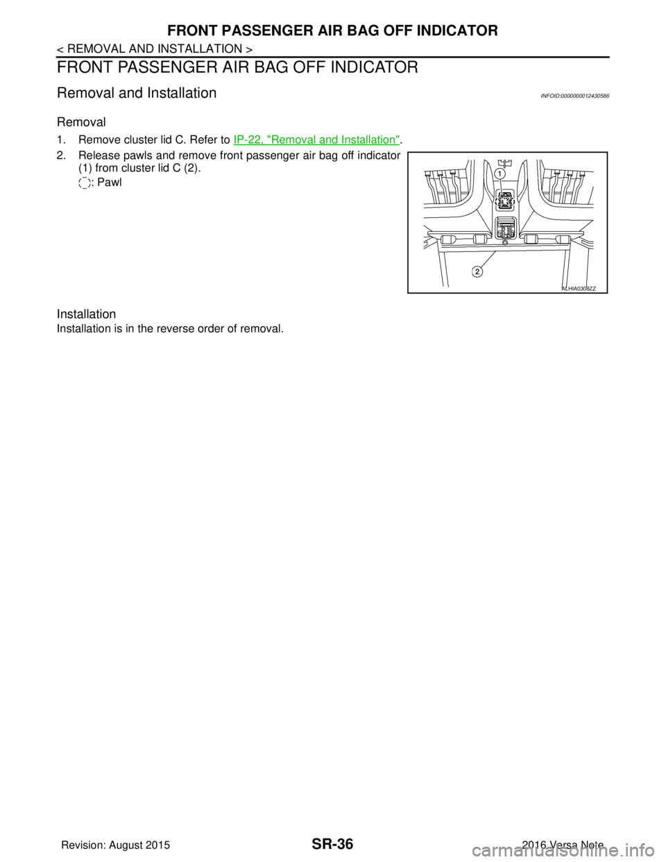
1. Remove cluster lid C. Refer to IP-22, "Removal and Installation".
2. Release pawls and remove front passenger air bag off indicator (1) from cluster lid C (2).
: Pawl
Installation
Installation is in the reverse order of removal.
ALHIA0308ZZ
Revision: August 2015 2016 Versa Note
cardiagn.com
Page 3153 of 3641

STR-1
ENGINE
C
DE
F
G H
I
J
K L
M
SECTION STR
A
STR
N
O P
CONTENTS
STARTING SYSTEM
PRECAUTION ....... ........................................2
PRECAUTIONS .............................................. .....2
Precaution for Supplemental Restraint System
(SRS) "AIR BAG" and "SEAT BELT PRE-TEN-
SIONER" ............................................................. ......
2
PREPARATION ............................................3
PREPARATION .............................................. .....3
Special Service Tool ........................................... ......3
Commercial Service Tools ........................................3
SYSTEM DESCRIPTION ..............................4
COMPONENT PARTS ................................... .....4
STARTING SYSTEM (WITHOUT INTELLIGENT
KEY) ....................................................................... ......
4
STARTING SYSTEM (WITHOUT INTELLIGENT
KEY) : Component Parts Location ...................... ......
4
STARTING SYSTEM (WITHOUT INTELLIGENT
KEY) : Component Description .......................... ......
5
STARTING SYSTEM (WITH INTELLIGENT KEY) ......5
STARTING SYSTEM (WITH INTELLIGENT KEY)
: Component Parts Location ......................................
6
STARTING SYSTEM (WITH INTELLIGENT KEY)
: Component Description ..........................................
6
SYSTEM ..............................................................8
STARTING SYSTEM (WITHOUT INTELLIGENT
KEY) ....................................................................... ......
8
STARTING SYSTEM (WITHOUT INTELLIGENT
KEY) : System Diagram ...................................... ......
8
STARTING SYSTEM (WITHOUT INTELLIGENT
KEY) : System Description .................................. ......
8
STARTING SYSTEM (WITH INTELLIGENT KEY) ......8
STARTING SYSTEM (WITH INTELLIGENT KEY)
: System Diagram ......................................................
9
STARTING SYSTEM (WITH INTELLIGENT KEY)
: System Description ............................................ .....
9
WIRING DIAGRAM ......................................10
STARTING SYSTEM .........................................10
Wiring Diagram - With Intelligent Key System ..... ....10
Wiring Diagram - Without Intelligent Key System ....16
BASIC INSPECTION ....... ............................21
DIAGNOSIS AND REPAIR WORKFLOW ........21
Work Flow (With GR8-1200 NI) ........................... ....21
Work Flow (Without GR8-1200 NI) ..........................25
DTC/CIRCUIT DIAGNOSIS .........................27
B TERMINAL CIRCUIT .....................................27
Description ........................................................... ....27
Diagnosis Procedure ...............................................27
S CONNECTOR CIRCUIT .................................29
Description ...............................................................29
Diagnosis Procedure ...............................................29
SYMPTOM DIAGNOSIS ..............................30
STARTING SYSTEM .........................................30
Symptom Table ................................................... ....30
REMOVAL AND INSTALLATION ...............31
STARTER MOTOR ...........................................31
Exploded View ..................................................... ....31
Removal and Installation .........................................31
SERVICE DATA AND SPECIFICATIONS
(SDS) ............... .......................................... ...
32
SERVICE DATA AND SPECIFICATIONS
(SDS) .................................................................
32
Starter Motor ........................................................ ....32
Revision: August 2015 2016 Versa Note
cardiagn.com
Page 3154 of 3641

STR-2
< PRECAUTION >
PRECAUTIONS
PRECAUTION
PRECAUTIONS
Precaution for Supplemental Restraint System (SRS) "AIR BAG" and "SEAT BELT
PRE-TENSIONER"
INFOID:0000000012432057
The Supplemental Restraint System such as “A IR BAG” and “SEAT BELT PRE-TENSIONER”, used along
with a front seat belt, helps to reduce the risk or severity of injury to the driver and front passenger for certain
types of collision. Information necessary to service the system safely is included in the SR and SB section of
this Service Manual.
WARNING:
• To avoid rendering the SRS inopera tive, which could increase the risk of personal injury or death in
the event of a collision which would result in air bag inflation, all maintenance must be performed by
an authorized NISSAN/INFINITI dealer.
• Improper maintenance, including in correct removal and installation of the SRS, can lead to personal
injury caused by unintent ional activation of the system. For re moval of Spiral Cable and Air Bag
Module, see the SR section.
• Do not use electrical test equipmen t on any circuit related to the SRS unless instructed to in this
Service Manual. SRS wiring harn esses can be identified by yellow and/or orange harnesses or har-
ness connectors.
PRECAUTIONS WHEN USING POWER TOOLS (AIR OR ELECTRIC) AND HAMMERS
WARNING:
• When working near the Airbag Diagnosis Sensor Unit or other Airbag System sensors with the Igni-
tion ON or engine running, DO NOT use air or electri c power tools or strike near the sensor(s) with a
hammer. Heavy vibration could activate the sensor( s) and deploy the air bag(s), possibly causing
serious injury.
• When using air or electric power tools or hammers , always switch the Ignition OFF, disconnect the
battery and wait at least three minutes before performing any service.
Revision: August 2015 2016 Versa Note
cardiagn.com
Page 3155 of 3641
PREPARATIONSTR-3
< PREPARATION >
C
DE
F
G H
I
J
K L
M A
STR
NP
O
PREPARATION
PREPARATION
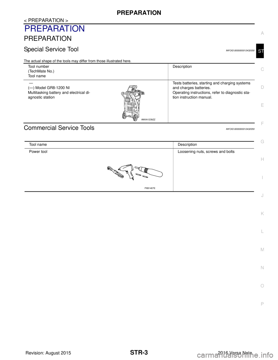
Special Service ToolINFOID:0000000012432058
The actual shape of the tools may di
ffer from those illustrated here.
Commercial Service ToolsINFOID:0000000012432059
Tool number
(TechMate No.)
Tool name Description
—
(—) Model GR8-1200 NI
Multitasking battery and electrical di-
agnostic station Tests batteries, starting and charging systems
and charges batteries.
Operating instructions, refer to diagnostic sta-
tion instruction manual.
AWIIA1239ZZ
Tool name
Description
Power tool Loosening nuts, screws and bolts
PIIB1407E
Revision: August 2015 2016 Versa Note
cardiagn.com
Page 3156 of 3641
STR-4
< SYSTEM DESCRIPTION >
COMPONENT PARTS
SYSTEM DESCRIPTION
COMPONENT PARTS
STARTING SYSTEM (WITHOUT INTELLIGENT KEY)
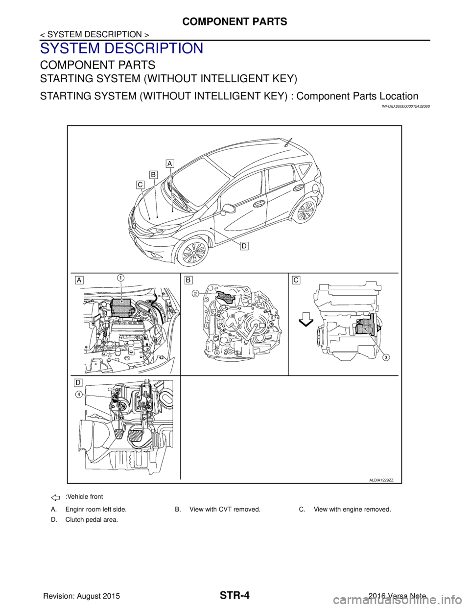
STARTING SYSTEM (WITHOUT INTELLIGENT KEY) : Component Parts Location
INFOID:0000000012432060
:Vehicle front
A. Enginr room left side. B. View with CVT removed. C. View with engine removed.
D. Clutch pedal area.
ALBIA1229ZZ
Revision: August 2015 2016 Versa Note
cardiagn.com
Page 3157 of 3641

COMPONENT PARTSSTR-5
< SYSTEM DESCRIPTION >
C
DE
F
G H
I
J
K L
M A
STR
NP
O
STARTING SYSTEM (WITHOUT INTELL
IGENT KEY) : Component Description
INFOID:0000000012432061
STARTING SYSTEM (WITH INTELLIGENT KEY)
No.Component part Description
1. IPDM E/R CPU inside IPDM E/R operates the starter control relay when
the ignition switch is in the start position.
2. Transmission range switch (CVT Models) Supplies power to the starter co
ntrol relay (inside IPDM E/R)
when the selector lever is shifted into the P or N position.
3. Starter motor The starter motor plunger closes and the motor is supplied
with battery power, which in turn cranks the engine, when the
S terminal is supplied with electric power.
4. Clutch interlock switch (M/T Models) Clutch interlock switch supplies power to the coil side of the
starter control relay when the clutch pedal is depressed to
crank the engine.
Revision: August 2015
2016 Versa Note
cardiagn.com
Page 3158 of 3641
STR-6
< SYSTEM DESCRIPTION >
COMPONENT PARTS
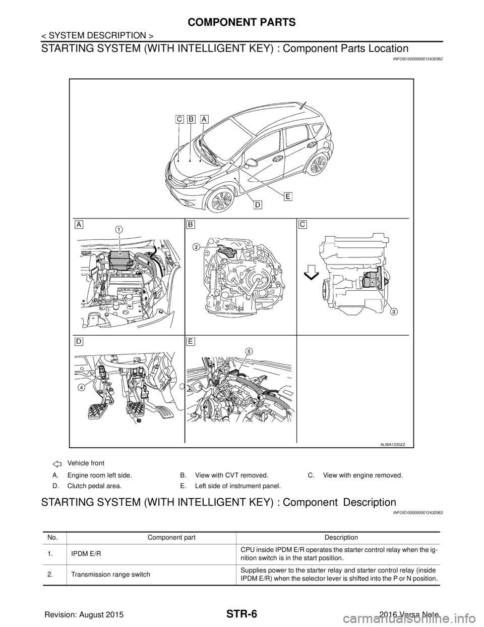
STARTING SYSTEM (WITH INTELLIGEN T KEY) : Component Parts Location
INFOID:0000000012432062
STARTING SYSTEM (WITH INTELLIGENT KEY) : Component Description
INFOID:0000000012432063
Vehicle front
A. Engine room left side. B. View with CVT removed. C. View with engine removed.
D. Clutch pedal area. E. Left side of instrument panel.
ALBIA1230ZZ
No. Component part Description
1. IPDM E/R CPU inside IPDM E/R operates the starter control relay when the ig-
nition switch is in the start position.
2. Transmission range switch Supplies power to the starter relay
and starter control relay (inside
IPDM E/R) when the selector lever is shifted into the P or N position.
Revision: August 2015 2016 Versa Note
cardiagn.com
Page 3159 of 3641

COMPONENT PARTSSTR-7
< SYSTEM DESCRIPTION >
C
DE
F
G H
I
J
K L
M A
STR
NP
O
3. Starter motor
The starter motor plunger closes and the motor is supplied with bat-
tery power, which in turn cranks the engine, when the S terminal is
supplied with electric power.
4. Clutch interlock switch (M/T) Clutch interlock switch supplies power to the coil side of the starter
relay and starter control relay (inside IPDM E/R) when the clutch
pedal is depressed to crank the engine.
5. BCM BCM controls the starter relay.
Revision: August 2015 2016 Versa Note
cardiagn.com
Page 3160 of 3641
STR-8
< SYSTEM DESCRIPTION >
SYSTEM
SYSTEM
STARTING SYSTEM (WITHOUT INTELLIGENT KEY)
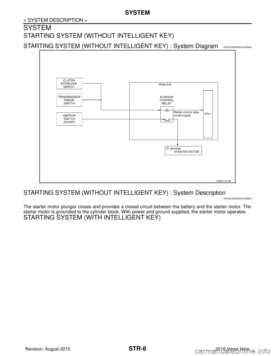
STARTING SYSTEM (WITHOUT INTELLIGENT KEY) : System DiagramINFOID:0000000012432064
STARTING SYSTEM (WITHOUT INTELLI GENT KEY) : System Description
INFOID:0000000012432065
The starter motor plunger closes and provides a closed circuit between the battery and the starter motor. The
starter motor is grounded to the cylinder block. With power and ground supplied, the starter motor operates.
STARTING SYSTEM (WITH INTELLIGENT KEY)
ALBIA1161GB
Revision: August 2015 2016 Versa Note
cardiagn.com