NISSAN NOTE 2016 Service Repair Manual
Manufacturer: NISSAN, Model Year: 2016, Model line: NOTE, Model: NISSAN NOTE 2016Pages: 3641, PDF Size: 28.72 MB
Page 3131 of 3641
DRIVER AIR BAG MODULESR-15
< REMOVAL AND INSTALLATION >
C
DE
F
G
I
J
K L
M A
B
SR
N
O P
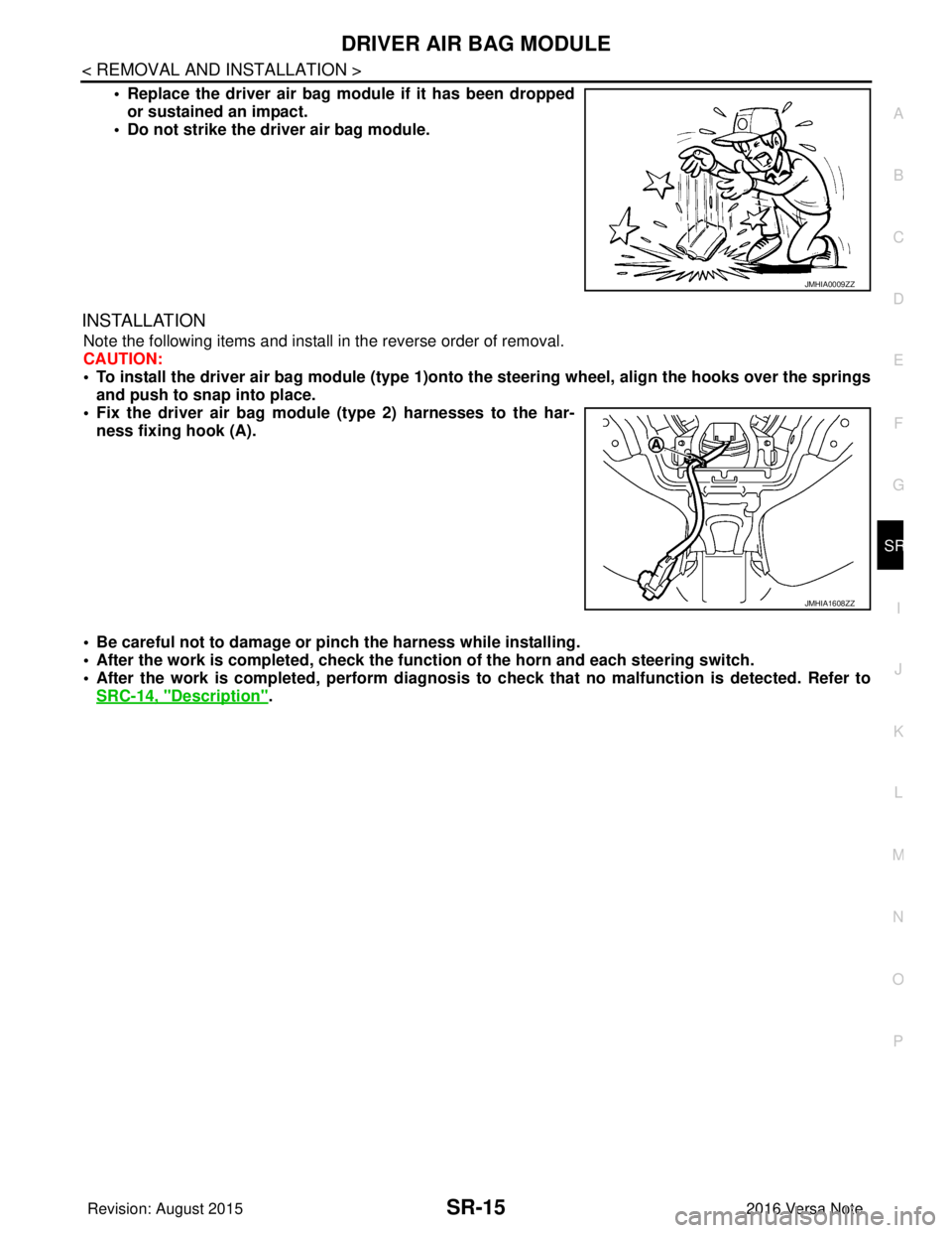
• Replace the driver air bag module if it has been dropped or sustained an impact.
• Do not strike the driver air bag module.
INSTALLATION
Note the following items and install in the reverse order of removal.
CAUTION:
• To install the driver air bag module (type 1)onto the steering wheel, align the hooks over the springs
and push to snap into place.
• Fix the driver air bag module (type 2) harnesses to the har- ness fixing hook (A).
• Be careful not to damage or pinch the harness while installing.
• After the work is completed, check the function of the horn and each steering switch.
• After the work is completed, perform diagnosis to check that no malfunction is detected. Refer to
SRC-14, "
Description".
JMHIA0009ZZ
JMHIA1608ZZ
Revision: August 2015 2016 Versa Note
cardiagn.com
Page 3132 of 3641
SR-16
< REMOVAL AND INSTALLATION >
SPIRAL CABLE
SPIRAL CABLE
Exploded ViewINFOID:0000000012430568
Removal and InstallationINFOID:0000000012430569
WARNING:
• Before servicing the SRS, turn ignition switch OFF, disconnect bot h battery terminals then wait at
least three minutes.
• Do not disassemble the spiral cable.
• Do not use air tools or el ectric tools for servicing.
CAUTION:
• Do not allow oil, grease, detergent or water to come in contact with the spiral cable.
REMOVAL
1. Disconnect negative and positive battery terminals, then wait at least three minutes. Refer to PG-70,
"Removal and Installation (Battery)".
2. Remove steering wheel. Refer to ST-8, "
Removal and Installation".
3. Remove steering column covers. Refer to IP-17, "
Removal and Installation".
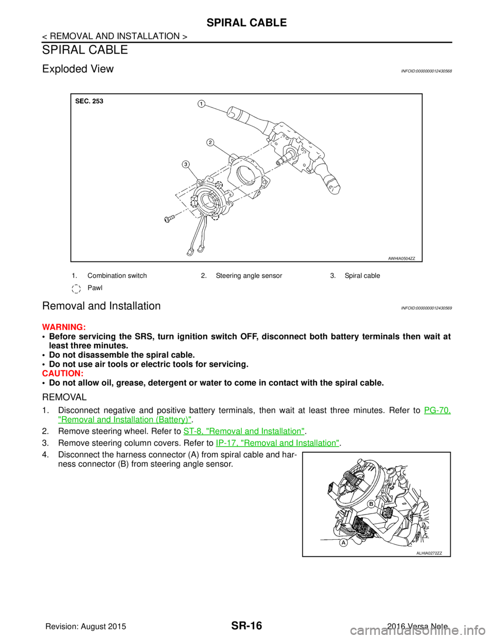
4. Disconnect the harness connector (A) from spiral cable and har- ness connector (B) from steering angle sensor.
1. Combination switch 2. Steering angle sensor3. Spiral cable
Pawl
AWHIA0504ZZ
ALHIA0272ZZ
Revision: August 2015 2016 Versa Note
cardiagn.com
Page 3133 of 3641
SPIRAL CABLESR-17
< REMOVAL AND INSTALLATION >
C
DE
F
G
I
J
K L
M A
B
SR
N
O P
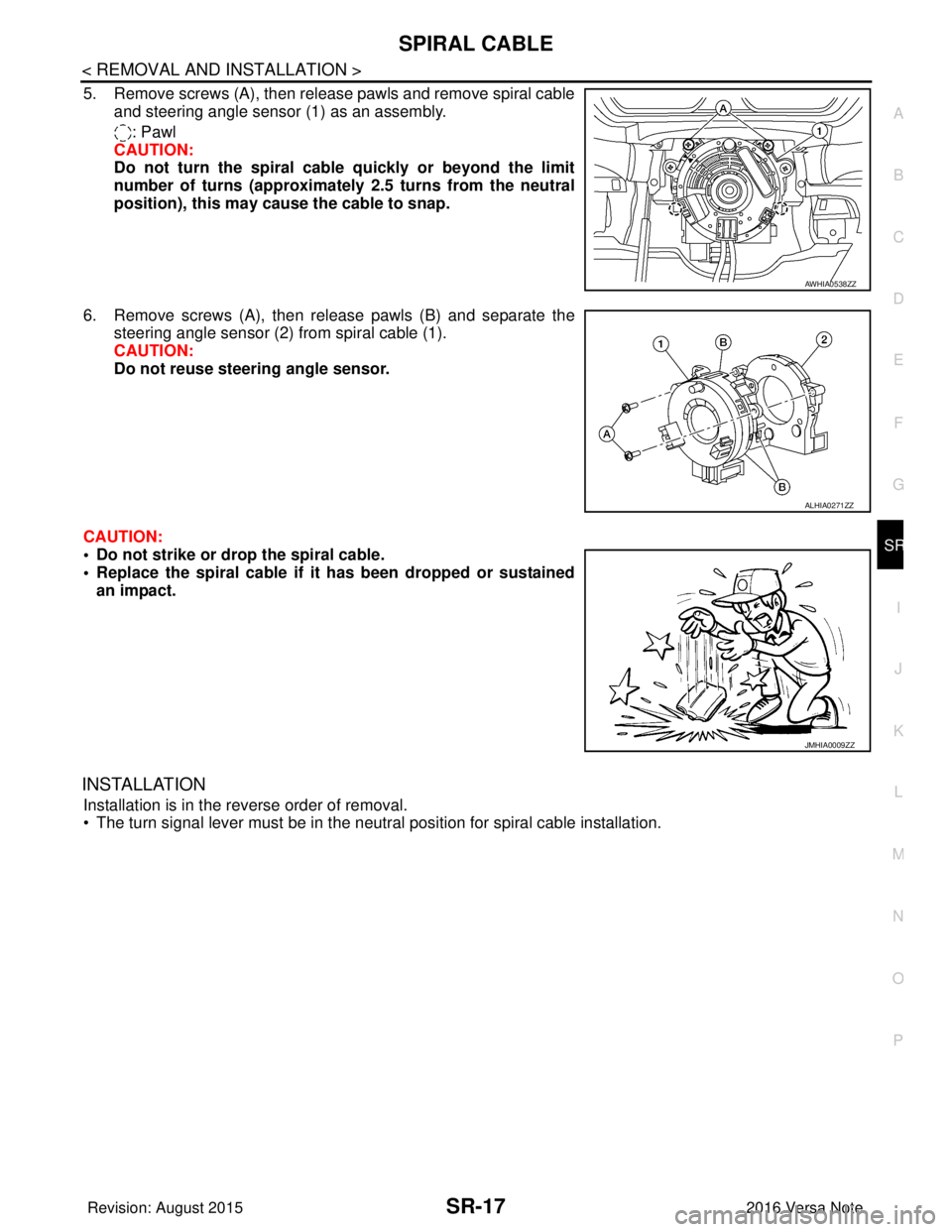
5. Remove screws (A), then release pawls and remove spiral cable and steering angle sensor (1) as an assembly.
: Pawl
CAUTION:
Do not turn the spiral cable quickly or beyond the limit
number of turns (approximately 2.5 turns from the neutral
position), this may cause the cable to snap.
6. Remove screws (A), then release pawls (B) and separate the steering angle sensor (2) from spiral cable (1).
CAUTION:
Do not reuse steering angle sensor.
CAUTION:
• Do not strike or drop the spiral cable.
• Replace the spiral cable if it has been dropped or sustained
an impact.
INSTALLATION
Installation is in the reverse order of removal.
• The turn signal lever must be in the neutral position for spiral cable installation.
AWHIA0538ZZ
ALHIA0271ZZ
JMHIA0009ZZ
Revision: August 2015 2016 Versa Note
cardiagn.com
Page 3134 of 3641
SR-18
< REMOVAL AND INSTALLATION >
SPIRAL CABLE
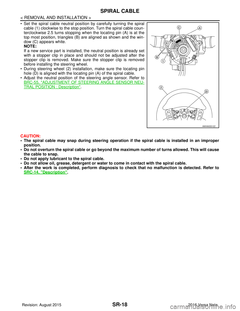
• Set the spiral cable neutral position by carefully turning the spiralcable (1) clockwise to the stop position. Turn the spiral cable coun-
terclockwise 2.5 turns stopping when the locating pin (A) is at the
top most position, triangles (B) are aligned as shown and the win-
dow (C) appears white.
NOTE:
If a new service part is installed, the neutral position is already set
with a stopper clip in place and should not be adjusted after the
stopper clip is removed. Make sure the stopper clip is removed
before installing the steering wheel.
• During steering wheel (2) installation, make sure the locating pin hole (D) is aligned with the locating pin (A) of the spiral cable.
• Adjust the neutral position of the steering angle sensor. Refer to
BRC-55, "
ADJUSTMENT OF STEERI NG ANGLE SENSOR NEU-
TRAL POSITION : Description".
CAUTION:
• The spiral cable may snap during steering operation if the spiral cable is installed in an improper
position.
• Do not overturn the spiral cable or go beyond the maximum number of turns allowed. This will cause
the cable to snap.
• Do not apply lubricant to the spiral cable.
• Do not allow oil, grease, detergent or water to come in contact with the spiral cable.
• After the work is completed, perform diagnosis to check that no malfunction is detected. Refer to
SRC-14, "
Description".
AWHIA0531ZZ
Revision: August 2015 2016 Versa Note
cardiagn.com
Page 3135 of 3641
FRONT PASSENGER AIR BAG MODULESR-19
< REMOVAL AND INSTALLATION >
C
DE
F
G
I
J
K L
M A
B
SR
N
O P
FRONT PASSENGER AIR BAG MODULE
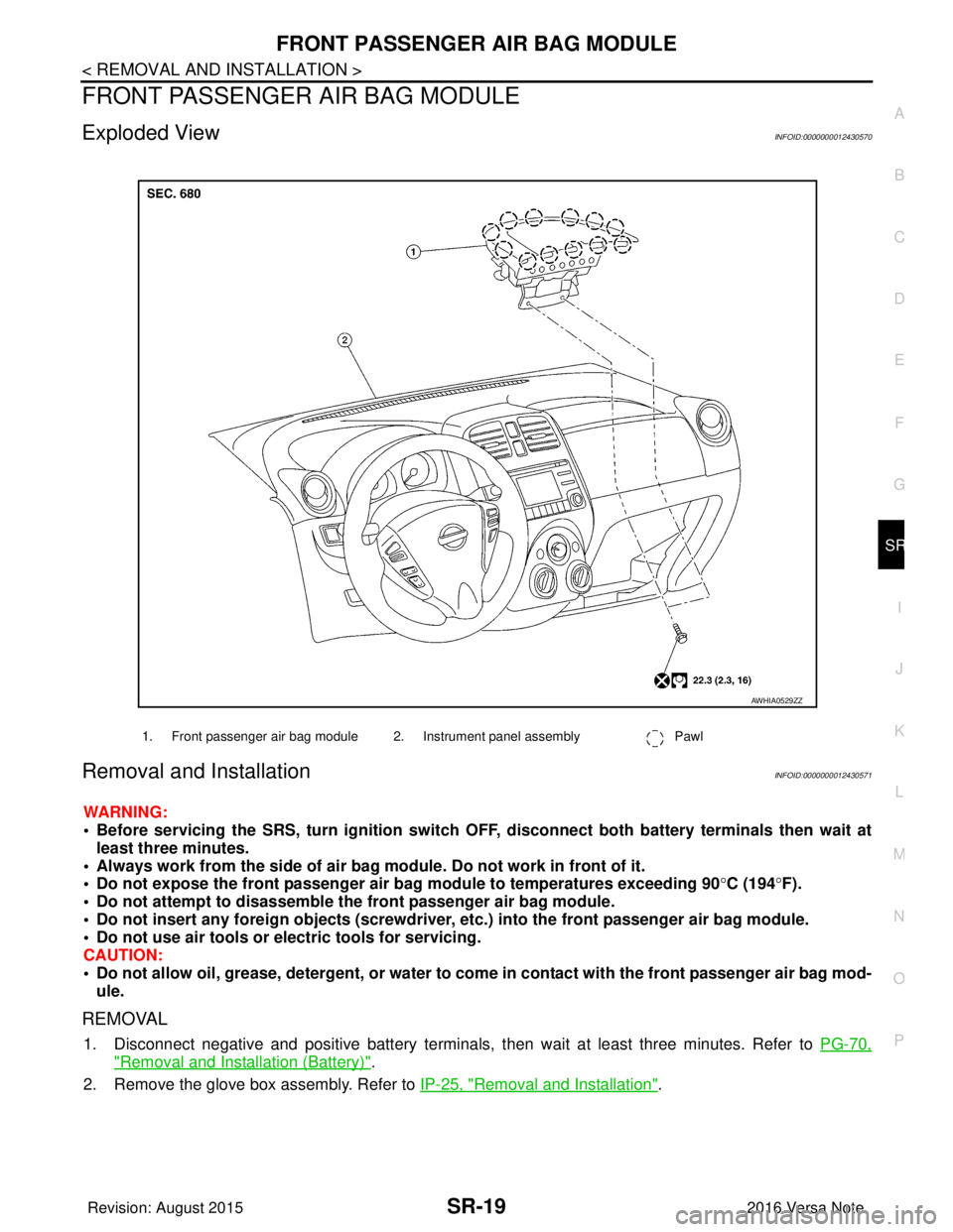
Exploded ViewINFOID:0000000012430570
Removal and InstallationINFOID:0000000012430571
WARNING:
• Before servicing the SRS, turn ig nition switch OFF, disconnect both battery terminals then wait at
least three minutes.
• Always work from the side of air bag module. Do not work in front of it.
• Do not expose the front passenger air bag module to temperatures exceeding 90 °C (194° F).
• Do not attempt to disassemble the front passenger air bag module.
• Do not insert any foreign objects (screwdriver, etc.) into the front passenger air bag module.
• Do not use air tools or electric tools for servicing.
CAUTION:
• Do not allow oil, grease, detergent, or water to co me in contact with the front passenger air bag mod-
ule.
REMOVAL
1. Disconnect negative and positive battery terminals, then wait at least three minutes. Refer to PG-70,
"Removal and Installation (Battery)".
2. Remove the glove box assembly. Refer to IP-25, "
Removal and Installation".
1. Front passenger air bag module 2. Instrument panel assembly Pawl
AWHIA0529ZZ
Revision: August 2015 2016 Versa Note
cardiagn.com
Page 3136 of 3641
SR-20
< REMOVAL AND INSTALLATION >
FRONT PASSENGER AIR BAG MODULE
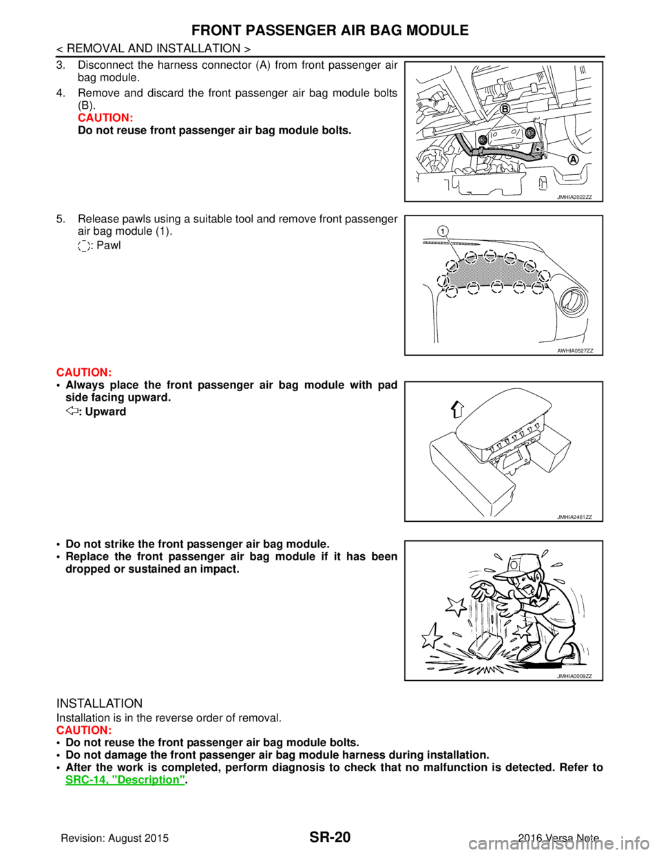
3. Disconnect the harness connector (A) from front passenger airbag module.
4. Remove and discard the front passenger air bag module bolts (B).
CAUTION:
Do not reuse front passenger air bag module bolts.
5. Release pawls using a suitable tool and remove front passenger air bag module (1).
: Pawl
CAUTION:
• Always place the front passenger air bag module with pad side facing upward.
: Upward
• Do not strike the front passenger air bag module.
• Replace the front passenger air bag module if it has been dropped or sustained an impact.
INSTALLATION
Installation is in the reverse order of removal.
CAUTION:
• Do not reuse the front passenger air bag module bolts.
• Do not damage the front passenger air bag module harness during installation.
• After the work is completed, perform diagnosis to check that no malfunction is detected. Refer to
SRC-14, "
Description".
JMHIA2022ZZ
AWHIA0527ZZ
JMHIA2461ZZ
JMHIA0009ZZ
Revision: August 2015 2016 Versa Note
cardiagn.com
Page 3137 of 3641
SIDE CURTAIN AIR BAG MODULESR-21
< REMOVAL AND INSTALLATION >
C
DE
F
G
I
J
K L
M A
B
SR
N
O P
SIDE CURTAIN AIR BAG MODULE
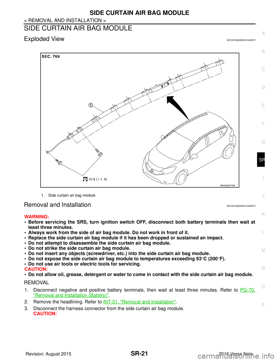
Exploded ViewINFOID:0000000012430572
Removal and InstallationINFOID:0000000012430573
WARNING:
• Before servicing the SRS, turn ig nition switch OFF, disconnect both battery terminals then wait at
least three minutes.
• Always work from the side of air bag module. Do not work in front of it.
• Replace the side curtain air bag module if it has been dropped or sustained an impact.
• Do not attempt to disassemble the side curtain air bag module.
• Do not strike the side curtain air bag module.
• Do not insert any objects (screwdriver, etc. ) into the side curtain air bag module.
• Do not expose the side curtain air bag module to temperatures exceeding 93 °C (200 °F).
• Do not use air tools or electric tools for servicing.
CAUTION:
• Do not allow oil, grease, detergent or water to come in contact with the side curtain air bag module.
REMOVAL
1. Disconnect negative and positive battery terminals, then wait at least three minutes. Refer to PG-70,
"Removal and Installation (Battery)".
2. Remove the headlining. Refer to INT-31, "
Removal and Installation".
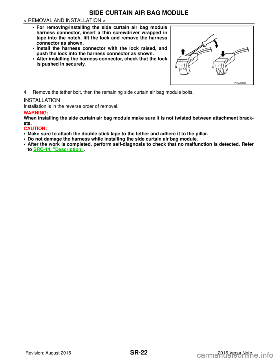
3. Disconnect the harness connector from the side curtain air bag module. CAUTION:
1. Side curtain air bag module
JMHIA2457GB
Revision: August 2015 2016 Versa Note
cardiagn.com
Page 3138 of 3641
SR-22
< REMOVAL AND INSTALLATION >
SIDE CURTAIN AIR BAG MODULE
• For removing/installing the side curtain air bag moduleharness connector, insert a thin screwdriver wrapped in
tape into the notch, lift the lock and remove the harness
connector as shown.
• Install the harness connector with the lock raised, and push the lock into the harness connector as shown.
• After installing the harness connector, check that the lock
is pushed in securely.
4. Remove the tether bolt, then the remaining side curtain air bag module bolts.
INSTALLATION
Installation is in the reverse order of removal.
WARNING:
When installing the side curtain air bag module make sure it is not twisted between attachment brack-
ets.
CAUTION:
• Make sure to attach the double stick tape to the tether and adhere it to the pillar.
• Do not damage the harness while installi ng the side curtain air bag module.
• After the work is completed, perform self-diagnos is to check that no malfunction is detected. Refer
to SRC-14, "
Description".
PHIA0953J
Revision: August 2015 2016 Versa Note
cardiagn.com
Page 3139 of 3641

SIDE AIR BAG MODULESR-23
< REMOVAL AND INSTALLATION >
C
DE
F
G
I
J
K L
M A
B
SR
N
O P
SIDE AIR BAG MODULE
Removal and InstallationINFOID:0000000012430574
The side air bag module is part of the front seatback. Refer to SE-20, "DRIVER SIDE : Removal and Installa-
tion" (DRIVER SIDE) or SE-22, "PASSENGER SIDE : Removal and Installation" (PASSENGER SIDE).
Revision: August 2015 2016 Versa Note
cardiagn.com
Page 3140 of 3641
SR-24
< REMOVAL AND INSTALLATION >
CRASH ZONE SENSOR
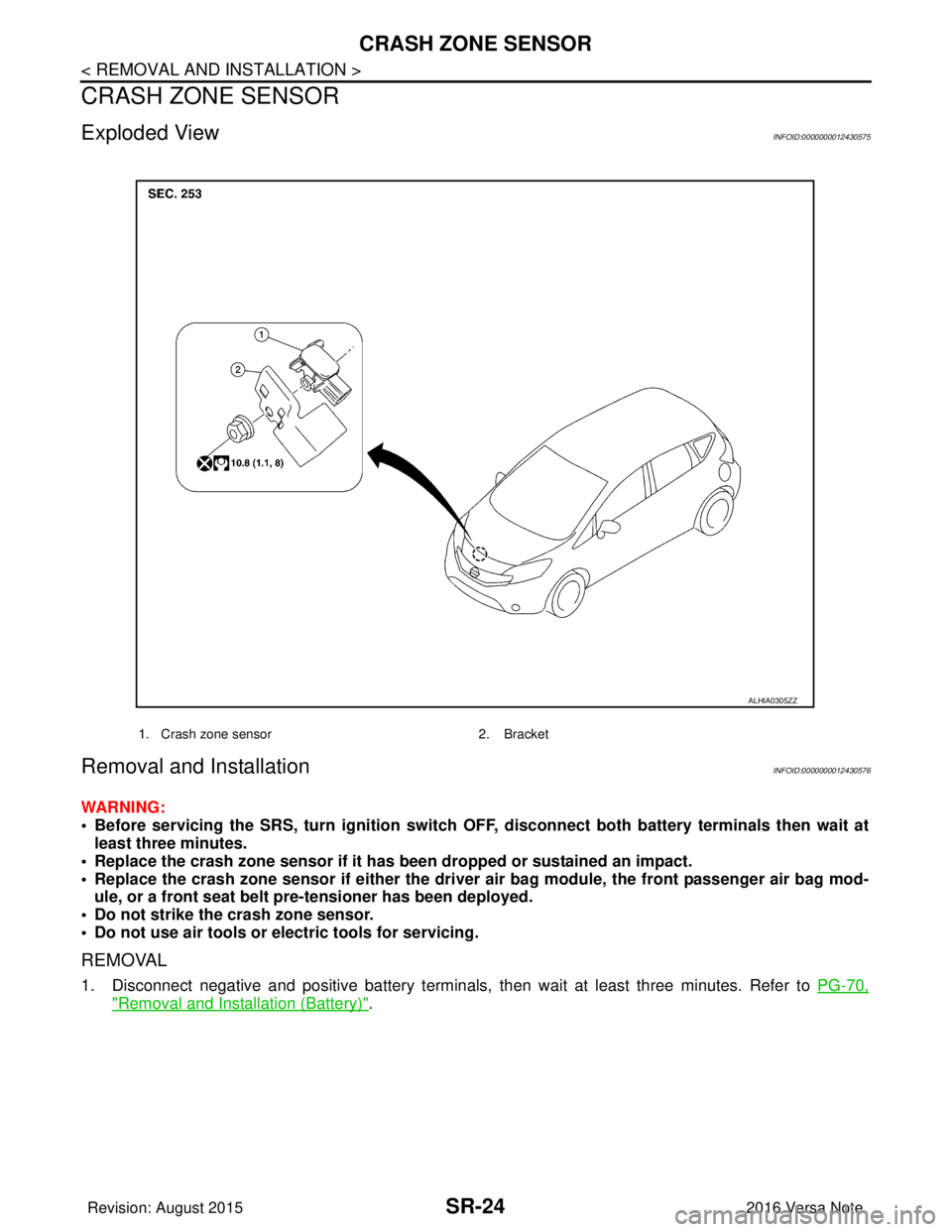
CRASH ZONE SENSOR
Exploded ViewINFOID:0000000012430575
Removal and InstallationINFOID:0000000012430576
WARNING:
• Before servicing the SRS, turn ignition switch OFF, disconnect bot h battery terminals then wait at
least three minutes.
• Replace the crash zone sensor if it has been dropped or sustained an impact.
• Replace the crash zone sensor if either the driver air bag module, the front passenger air bag mod- ule, or a front seat belt pre-tensioner has been deployed.
• Do not strike the crash zone sensor.
• Do not use air tools or el ectric tools for servicing.
REMOVAL
1. Disconnect negative and positive battery terminals, then wait at least three minutes. Refer to PG-70,
"Removal and Installation (Battery)".
1. Crash zone sensor 2. Bracket
ALHIA0305ZZ
Revision: August 2015 2016 Versa Note
cardiagn.com