charging NISSAN NOTE 2016 Service Repair Manual
[x] Cancel search | Manufacturer: NISSAN, Model Year: 2016, Model line: NOTE, Model: NISSAN NOTE 2016Pages: 3641, PDF Size: 28.72 MB
Page 217 of 3641
![NISSAN NOTE 2016 Service Repair Manual AV-212
< DTC/CIRCUIT DIAGNOSIS >[NAVIGATION]
U12B0 POWER SUPPLY VOLTAGE
U12B0 POWER SUPPLY VOLTAGE
DTC LogicINFOID:0000000012433076
DTC DETECTION LOGIC
Diagnosis ProcedureINFOID:0000000012433077
1.CHE NISSAN NOTE 2016 Service Repair Manual AV-212
< DTC/CIRCUIT DIAGNOSIS >[NAVIGATION]
U12B0 POWER SUPPLY VOLTAGE
U12B0 POWER SUPPLY VOLTAGE
DTC LogicINFOID:0000000012433076
DTC DETECTION LOGIC
Diagnosis ProcedureINFOID:0000000012433077
1.CHE](/img/5/57363/w960_57363-216.png)
AV-212
< DTC/CIRCUIT DIAGNOSIS >[NAVIGATION]
U12B0 POWER SUPPLY VOLTAGE
U12B0 POWER SUPPLY VOLTAGE
DTC LogicINFOID:0000000012433076
DTC DETECTION LOGIC
Diagnosis ProcedureINFOID:0000000012433077
1.CHECK CHARGING SYSTEM
Check the vehicle charging system. Refer to CHG-14, "
Work Flow (With EXP-800 NI or GR8-1200 NI)" or
CHG-17, "
Work Flow (Without EXP-800 NI or GR8-1200 NI)".
Is the inspection result normal?
YES >> GO TO 2.
NO >> Repair or replace the malfunctioning components.
2.CHECK AV CONTROL UNIT POWE R SUPPLY AND GROUND CIRCUITS
Perform the AV control unit power supply and ground circuit diagnosis procedure. Refer to AV-216, "
AV CON-
TROL UNIT : Diagnosis Procedure".
Is the inspection result normal?
YES >> Replace the AV control unit. Refer to AV- 2 4 1 , "Removal and Installation".
NO >> Repair or replace harness or connectors.
CONSULT Display DTC Detection Condition Possible Cause
Supply Voltage Goes below 9V
> 20s
[U12B0] AV control unit supply voltage exceeds lower lim-
its.
• Charging system malfunction.
• AV control unit power supply or ground circuits.
Revision: August 2015
2016 Versa Note
cardiagn.com
Page 218 of 3641
![NISSAN NOTE 2016 Service Repair Manual AV
U12B1 POWER SUPPLY VOLTAGEAV-213
< DTC/CIRCUIT DIAGNOSIS > [NAVIGATION]
C
D
E
F
G H
I
J
K L
M B A
O P
U12B1 POWER SUPPLY VOLTAGE
DTC LogicINFOID:0000000012433078
DTC DETECTION LOGIC
Diagnosis Proce NISSAN NOTE 2016 Service Repair Manual AV
U12B1 POWER SUPPLY VOLTAGEAV-213
< DTC/CIRCUIT DIAGNOSIS > [NAVIGATION]
C
D
E
F
G H
I
J
K L
M B A
O P
U12B1 POWER SUPPLY VOLTAGE
DTC LogicINFOID:0000000012433078
DTC DETECTION LOGIC
Diagnosis Proce](/img/5/57363/w960_57363-217.png)
AV
U12B1 POWER SUPPLY VOLTAGEAV-213
< DTC/CIRCUIT DIAGNOSIS > [NAVIGATION]
C
D
E
F
G H
I
J
K L
M B A
O P
U12B1 POWER SUPPLY VOLTAGE
DTC LogicINFOID:0000000012433078
DTC DETECTION LOGIC
Diagnosis ProcedureINFOID:0000000012433079
1.CHECK CHARGING SYSTEM
Check the vehicle charging system. Refer to CHG-14, "
Work Flow (With EXP-800 NI or GR8-1200 NI)" or
CHG-17, "
Work Flow (Without EXP-800 NI or GR8-1200 NI)".
Is the inspection result normal?
YES >> Replace the AV control unit. Refer to AV-241, "Removal and Installation".
NO >> Repair or replace the malfunctioning components.
CONSULT Display DTC Detection Condition Possible Cause
Supply Voltage Goes High >
16V for 20s
[U12B1] AV control unit supply voltage exceeds upper lim-
its.
Charging system malfunction.
Revision: August 2015
2016 Versa Note
cardiagn.com
Page 596 of 3641

CHG
CHG-1
ELECTRICAL & POWER CONTROL
C
DE
F
G H
I
J
K L
B
SECTION CHG
A
O P
N
CONTENTS
CHARGING SYSTEM
PRECAUTION .......
........................................3
PRECAUTIONS .............................................. .....3
Precaution for Supplemental Restraint System
(SRS) "AIR BAG" and "SEAT BELT PRE-TEN-
SIONER" ............................................................. ......
3
Precaution for Power Generation Voltage Variable
Control System ..........................................................
3
PREPARATION ............................................4
PREPARATION .............................................. .....4
Special Service Tool ........................................... ......4
Commercial Service Tool ..........................................4
SYSTEM DESCRIPTION ..............................5
COMPONENT PARTS ................................... .....5
Component Parts Location .................................. ......5
Component Description .............................................6
SYSTEM ..............................................................7
CHARGING SYSTEM ..................................................7
CHARGING SYSTEM : System Diagram ........... ......7
CHARGING SYSTEM : System Description .............7
CHARGING SYSTEM : Component Description ......7
POWER GENERATION VOLTAGE VARI-
ABLE CONTROL SYSTEM .................................
8
System Diagram .................................................. ......8
System Description ...................................................8
WIRING DIAGRAM .......................................9
CHARGING SYSTEM ..................................... .....9
Wiring Diagram ................................................... ......9
BASIC INSPECTION ...................................14
DIAGNOSIS AND REPAIR WORKFLOW ..... ....14
Work Flow (With EXP-800 NI or GR8-1200 NI) ......14
Work Flow (Without EXP-800 NI or GR8-1200 NI) ....17
DTC/CIRCUIT DIAGNOSIS .........................20
CHARGING SYSTEM PRELIMINARY IN-
SPECTION ....... .................................................
20
Diagnosis Procedure ........................................... ....20
POWER GENERATION VOLTAGE VARI-
ABLE CONTROL SYSTEM OPERATION IN-
SPECTION ........................................................
21
Diagnosis Procedure ........................................... ....21
B TERMINAL CIRCUIT .....................................23
Description ...............................................................23
Diagnosis Procedure ...............................................23
L TERMINAL CIRCUIT (OPEN) ........................24
Description ...............................................................24
Diagnosis Procedure ...............................................24
L TERMINAL CIRCUIT (SHORT) .....................26
Description ...............................................................26
Diagnosis Procedure ...............................................26
S TERMINAL CIRCUIT .....................................27
Description ...............................................................27
Diagnosis Procedure ...............................................27
SYMPTOM DIAGNOSIS ..............................28
CHARGING SYSTEM .......................................28
Symptom Table ................................................... ....28
REMOVAL AND INSTALLATION ...............29
GENERATOR ....................................................29
Exploded View ..................................................... ....29
Removal and Installation .........................................29
SERVICE DATA AND SPECIFICATIONS
(SDS) ............... .......................................... ...
31
Revision: August 2015 2016 Versa Note
cardiagn.com
Page 598 of 3641
CHG
PRECAUTIONSCHG-3
< PRECAUTION >
C
DE
F
G H
I
J
K L
B A
O P
N
PRECAUTION
PRECAUTIONS
Precaution for Supplemental
Restraint System (SRS) "AIR BAG" and "SEAT BELT
PRE-TENSIONER"
INFOID:0000000012431235
The Supplemental Restraint System such as “AIR BAG” and “SEAT BELT PRE-TENSIONER”, used along
with a front seat belt, helps to reduce the risk or severi ty of injury to the driver and front passenger for certain
types of collision. Information necessary to service the system safely is included in the SR and SB section of
this Service Manual.
WARNING:
• To avoid rendering the SRS inoper ative, which could increase the risk of personal injury or death in
the event of a collision which would result in air bag inflation, all maintenance must be performed by
an authorized NISSAN/INFINITI dealer.
• Improper maintenance, including in correct removal and installation of the SRS, can lead to personal
injury caused by unintentional act ivation of the system. For removal of Spiral Cable and Air Bag
Module, see the SR section.
• Do not use electrical test equipm ent on any circuit related to the SRS unless instructed to in this
Service Manual. SRS wiring harnesses can be identi fied by yellow and/or orange harnesses or har-
ness connectors.
PRECAUTIONS WHEN USING POWER TOOLS (AIR OR ELECTRIC) AND HAMMERS
WARNING:
• When working near the Airbag Diagnosis Sensor Un it or other Airbag System sensors with the Igni-
tion ON or engine running, DO NOT use air or el ectric power tools or strike near the sensor(s) with a
hammer. Heavy vibration could activate the sensor( s) and deploy the air bag(s), possibly causing
serious injury.
• When using air or electric power tools or hammers, always switch the Ignition OFF, disconnect the
battery and wait at least three mi nutes before performing any service.
Precaution for Power Generation Voltage Variable Control SystemINFOID:0000000012431236
CAUTION:
For model with power generation voltage variable control system, the battery current sensor that is
installed to the battery cable at the negative te rminal measures the charging/discharging current of
the battery, and performs various controls. If the electrical component or the ground wire is connected
directly to the battery terminal, the current othe r than that being measured with the battery current
sensor is charging to or discharging from the battery. This cond ition causes the malfunction of the
control, and then the battery discharge may occur. Do not connect the electrical component or the
ground wire directly to the battery terminal.
Revision: August 2015 2016 Versa Note
cardiagn.com
Page 599 of 3641
CHG-4
< PREPARATION >
PREPARATION
PREPARATION
PREPARATION
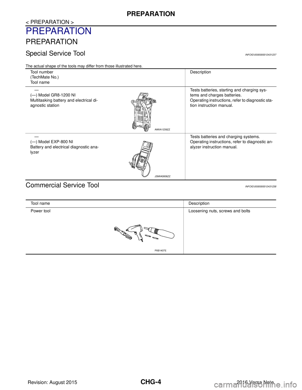
Special Service ToolINFOID:0000000012431237
The actual shape of the tools may differ from those illustrated here.
Commercial Service ToolINFOID:0000000012431238
Tool number
(TechMate No.)
Tool nameDescription
—
(—) Model GR8-1200 NI
Multitasking battery and electrical di-
agnostic station Tests batteries, starting and charging sys-
tems and charges batteries.
Operating instructions, refer to diagnostic sta-
tion instruction manual.
—
(—) Model EXP-800 NI
Battery and electrical diagnostic ana-
lyzer Tests batteries and charging systems.
Operating instructions, refer to diagnostic an-
alyzer instruction manual.
AWIIA1239ZZ
JSMIA0806ZZ
Tool name
Description
Power tool Loosening nuts, screws and bolts
PIIB1407E
Revision: August 2015 2016 Versa Note
cardiagn.com
Page 601 of 3641

CHG-6
< SYSTEM DESCRIPTION >
COMPONENT PARTS
Component Description
INFOID:0000000012431240
No. Component part Description
1 IPDM E/R The IPDM E/R converts the received power generation com-
mand value into a pulse width modulated (PWM) command sig-
nal and sends it to the IC regulator.
2ECM The battery current sensor detects the charging/discharging
current of the battery. The ECM judges the battery condition
based on this signal.
The ECM judges whether to request more output via the power
generation voltage variable control according to the battery
condition.
When performing the power generation voltage variable con-
trol, the ECM calculates the target power generation voltage
according to the battery condition and sends the calculated val-
ue as the power generation command value to the IPDM E/R.
3 Battery current sensor The battery current sensor is located on the negative battery
cable terminal. The battery current sensor detects the charg-
ing/discharging current of the battery and sends a voltage sig-
nal to the ECM according to the current value detected.
4 Generator (IC regulator) The IC regulator controls the power generation voltage by the
target power generation voltage based on the received PWM
command signal.
When there is no PWM command signal, the generator per-
forms the normal power generation according to the character-
istic of the IC regulator.
5 Combination meter (charge warning lamp) The IC regulator warning function activates to illuminate the
charge warning lamp if any of the following symptoms occur
while generator is operating:
• Excessive voltage is produced.
• No voltage is produced.
Revision: August 2015
2016 Versa Note
cardiagn.com
Page 602 of 3641
CHG
SYSTEMCHG-7
< SYSTEM DESCRIPTION >
C
DE
F
G H
I
J
K L
B A
O P
N
SYSTEM
CHARGING SYSTEM
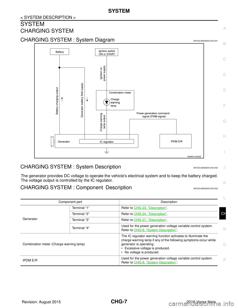
CHARGING SYSTEM : System DiagramINFOID:0000000012431241
CHARGING SYSTEM : System DescriptionINFOID:0000000012431242
The generator provides DC voltage to operate the vehicl
e's electrical system and to keep the battery charged.
The voltage output is controlled by the IC regulator.
CHARGING SYSTEM : Component DescriptionINFOID:0000000012431243
AWMIA1334GB
Component part Description
Generator Terminal “1”
Refer to CHG-23, "
Description".
Terminal “2” Refer to CHG-24, "
Description".
Terminal “3” Refer to CHG-27, "
Description".
Terminal “4” Used for the power generation voltage variable control system.
Refer to CHG-8, "
System Description".
Combination meter (C harge warning lamp) The IC regulator warning function activates to illuminate the
charge warning lamp if any of the following symptoms occur while
generator is operating:
• Excessive voltage is produced.
• No voltage is produced.
IPDM E/R Used for the power generation voltage variable control system.
Refer to CHG-8, "
System Description".
Revision: August 2015
2016 Versa Note
cardiagn.com
Page 604 of 3641
CHG
CHARGING SYSTEMCHG-9
< WIRING DIAGRAM >
C
DE
F
G H
I
J
K L
B A
O P
N
WIRING DIAGRAM
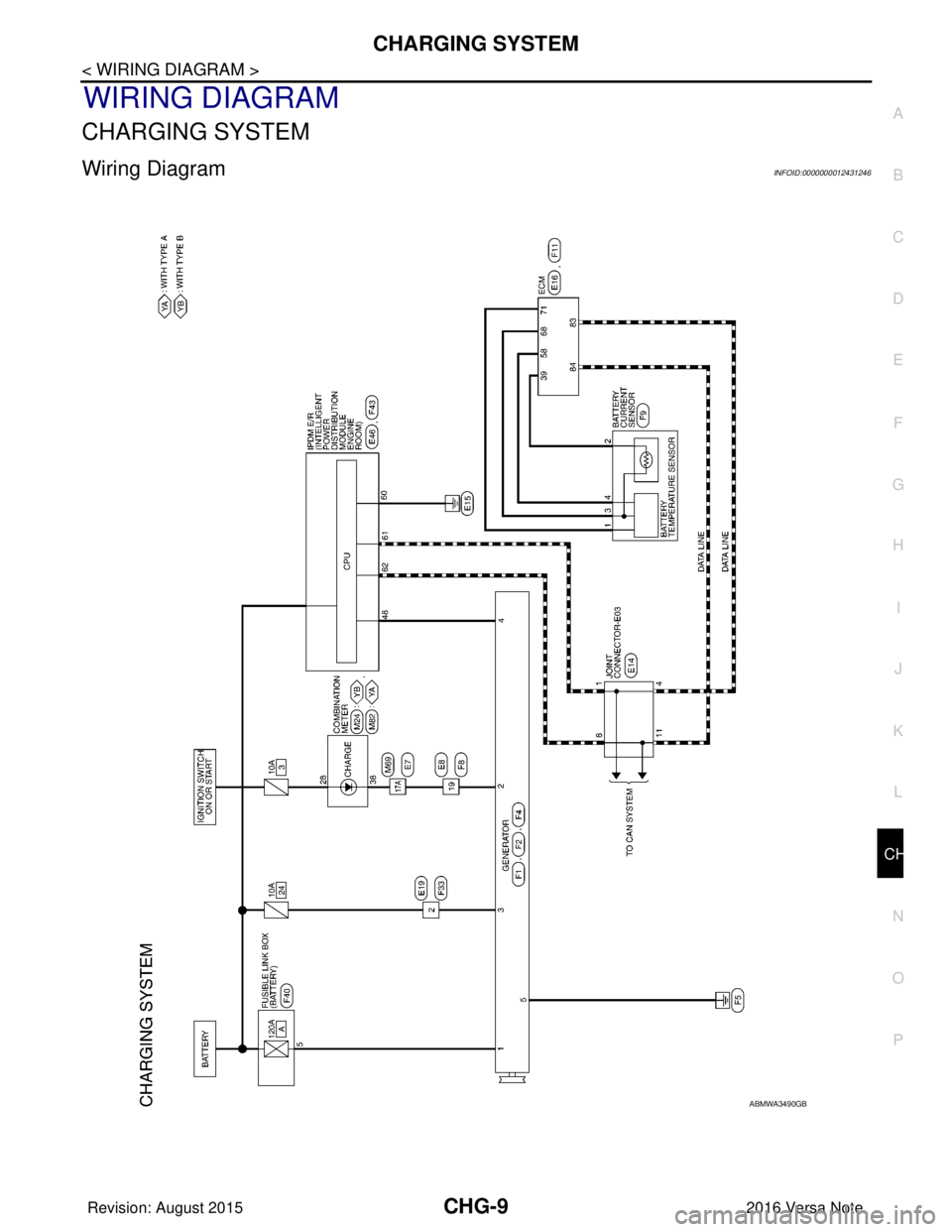
CHARGING SYSTEM
Wiring DiagramINFOID:0000000012431246
ABMWA3490GB
Revision: August 2015
2016 Versa Note
cardiagn.com
Page 605 of 3641
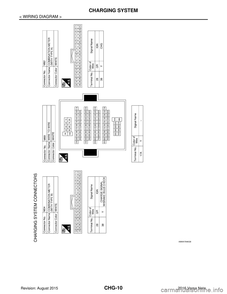
CHG-10
< WIRING DIAGRAM >
CHARGING SYSTEM
ABMIA7846GB
Revision: August 20152016 Versa Note
cardiagn.com
Page 606 of 3641
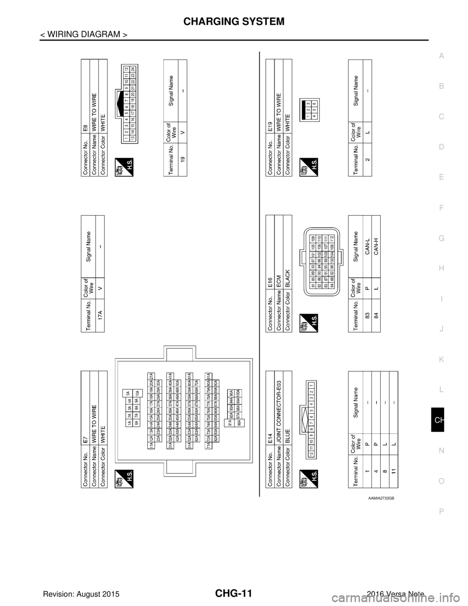
CHG
CHARGING SYSTEMCHG-11
< WIRING DIAGRAM >
C
DE
F
G H
I
J
K L
B A
O P
N
AAMIA2732GB
Revision: August 2015
2016 Versa Note
cardiagn.com