Fuse block NISSAN PATROL 1998 Y61 / 5.G Electrical System User Guide
[x] Cancel search | Manufacturer: NISSAN, Model Year: 1998, Model line: PATROL, Model: NISSAN PATROL 1998 Y61 / 5.GPages: 326, PDF Size: 11.36 MB
Page 200 of 326
![NISSAN PATROL 1998 Y61 / 5.G Electrical System User Guide System Description
With ignition switch in ON or START position, power is supplied
+through 7.5A fuse [No.
8, located in the fuse block (J/B)]
+to power window relay terminalj
1.
The power window rela NISSAN PATROL 1998 Y61 / 5.G Electrical System User Guide System Description
With ignition switch in ON or START position, power is supplied
+through 7.5A fuse [No.
8, located in the fuse block (J/B)]
+to power window relay terminalj
1.
The power window rela](/img/5/616/w960_616-199.png)
System Description
With ignition switch in ON or START position, power is supplied
+through 7.5A fuse [No.
8, located in the fuse block (J/B)]
+to power window relay terminalj
1.
The power window relay is energized and power is supplied
+through power window relay terminalj
5
+to power window main switch terminalj1,
+to power window sub switch terminalj
5.
MANUAL OPERATION
NOTE:
Numbers in parentheses are terminal numbers, when power window switch is pressed in the UP and DOWN
positions respectively.
Driver side
When the driver side switch in the power window main switch is pressed in the up position, power is supplied
+to driver side power window regulator terminal (j
2,j1)
+through power window main switch terminal (j
9,j8).
Ground is supplied
+to driver side power window regulator terminal (j
1,j2)
+through power window main switch terminal (j
8,j9).
Then, the motor raises or lowers the window until the switch is released.
Passenger side
MAIN SWITCH OPERATION
Power is supplied
+through power window main switch (j
5,j6)
+to front power window sub-switch (j
3,j4).
The subsequent operation is the same as the sub-switch operation.
SUB-SWITCH OPERATION
Power is supplied
+through front power window sub-switch (j
1,j2)
+to passenger side power window regulator (j
2,j1).
Ground is supplied
+to passenger side power window regulator (j
1,j2)
+through front power window sub-switch (j
2,j1)
+to front power window sub-switch (j
4,j3)
+through power window main switch (j
6,j5).
Then, the motor raises or lowers the window until the switch is released.
Rear door
Rear door windows will raise and lower in the same manner as passenger side door window.
AUTO OPERATION
The power window AUTO feature enables the driver to open or close the driver's window without holding the
window switch in the respective position.
When the AUTO switch in the main switch is pressed and released, the driver's window will travel to the fully
open or closed position.
POWER WINDOW LOCK
The power window lock is designed to lock operation of all windows except for driver's door window.
When the lock switch is pressed to lock position, ground of the sub-switches in the power window main switch
is disconnected. This prevents the power window motors from operating.
POWER WINDOW
EL-196
Page 207 of 326
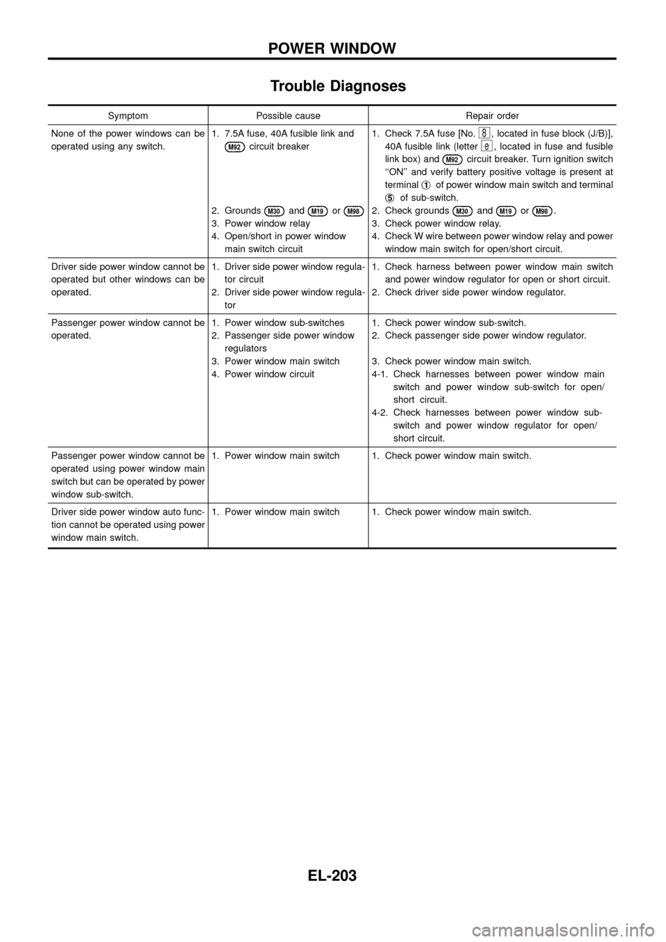
Trouble Diagnoses
Symptom Possible cause Repair order
None of the power windows can be
operated using any switch.1. 7.5A fuse, 40A fusible link and
M92circuit breaker
2. Grounds
M30andM19orM98
3. Power window relay
4. Open/short in power window
main switch circuit1. Check 7.5A fuse [No.
8, located in fuse block (J/B)],
40A fusible link (letter
e, located in fuse and fusible
link box) and
M92circuit breaker. Turn ignition switch
``ON'' and verify battery positive voltage is present at
terminalj
1of power window main switch and terminal
j
5of sub-switch.
2. Check grounds
M30andM19orM98.
3. Check power window relay.
4. Check W wire between power window relay and power
window main switch for open/short circuit.
Driver side power window cannot be
operated but other windows can be
operated.1. Driver side power window regula-
tor circuit
2. Driver side power window regula-
tor1. Check harness between power window main switch
and power window regulator for open or short circuit.
2. Check driver side power window regulator.
Passenger power window cannot be
operated.1. Power window sub-switches
2. Passenger side power window
regulators
3. Power window main switch
4. Power window circuit1. Check power window sub-switch.
2. Check passenger side power window regulator.
3. Check power window main switch.
4-1. Check harnesses between power window main
switch and power window sub-switch for open/
short circuit.
4-2. Check harnesses between power window sub-
switch and power window regulator for open/
short circuit.
Passenger power window cannot be
operated using power window main
switch but can be operated by power
window sub-switch.1. Power window main switch 1. Check power window main switch.
Driver side power window auto func-
tion cannot be operated using power
window main switch.1. Power window main switch 1. Check power window main switch.
POWER WINDOW
EL-203
Page 236 of 326
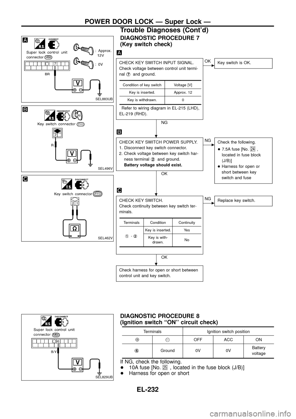
DIAGNOSTIC PROCEDURE 7
(Key switch check)
CHECK KEY SWITCH INPUT SIGNAL.
Check voltage between control unit termi-
nalj
7and ground.
Refer to wiring diagram in EL-215 (LHD),
EL-219 (RHD).
NG
cOK
Key switch is OK.
CHECK KEY SWITCH POWER SUPPLY.
1. Disconnect key switch connector.
2. Check voltage between key switch har-
ness terminalj
2and ground.
Battery voltage should exist.
OK
cNG
Check the following.
+7.5A fuse [No.
24,
located in fuse block
(J/B)]
+Harness for open or
short between key
switch and fuse
CHECK KEY SWITCH.
Check continuity between key switch ter-
minals.
OK
cNG
Replace key switch.
Check harness for open or short between
control unit and key switch.
Condition of key switch Voltage [V]
Key is inserted. Approx. 12
Key is withdrawn. 0
Terminals Condition Continuity
j
1-j2
Key is inserted. Yes
Key is with-
drawn.No
DIAGNOSTIC PROCEDURE 8
(Ignition switch ``ON'' circuit check)
Terminals Ignition switch position
Å@OFF ACC ON
j
6Ground 0V 0VBattery
voltage
If NG, check the following.
+10A fuse [No.
25, located in the fuse block (J/B)]
+Harness for open or short
SEL883UB
SEL496V
SEL462V
SEL829UB
.
.
.
POWER DOOR LOCK Ð Super Lock Ð
Trouble Diagnoses (Cont'd)
EL-232
Page 251 of 326
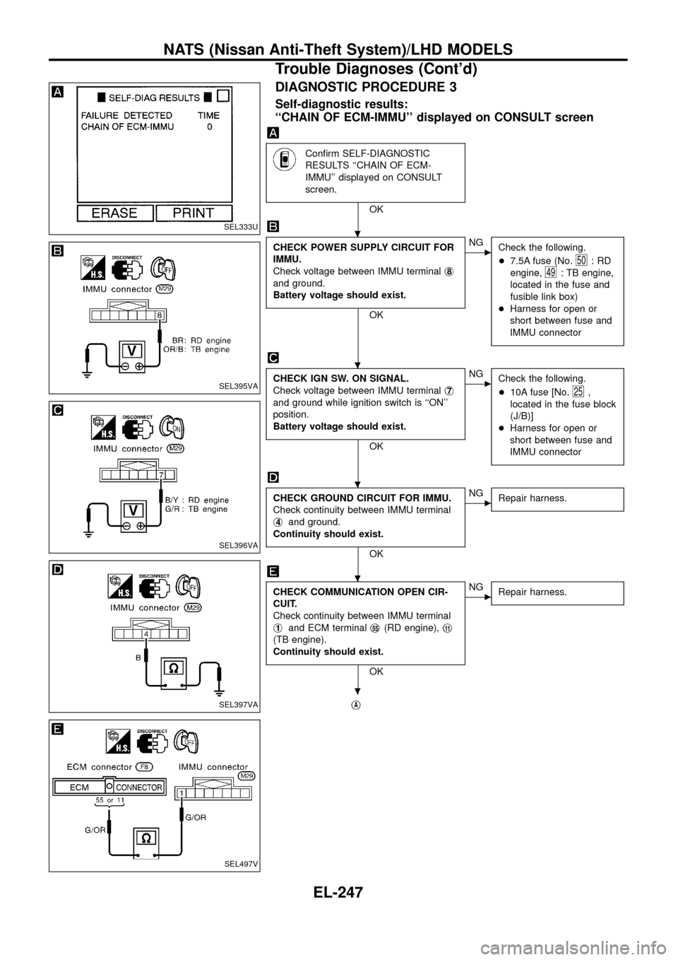
DIAGNOSTIC PROCEDURE 3
Self-diagnostic results:
``CHAIN OF ECM-IMMU'' displayed on CONSULT screen
Con®rm SELF-DIAGNOSTIC
RESULTS ``CHAIN OF ECM-
IMMU'' displayed on CONSULT
screen.
OK
CHECK POWER SUPPLY CIRCUIT FOR
IMMU.
Check voltage between IMMU terminalj
8
and ground.
Battery voltage should exist.
OK
cNG
Check the following.
+7.5A fuse (No.
50:RD
engine,
49: TB engine,
located in the fuse and
fusible link box)
+Harness for open or
short between fuse and
IMMU connector
CHECK IGN SW. ON SIGNAL.
Check voltage between IMMU terminalj
7
and ground while ignition switch is ``ON''
position.
Battery voltage should exist.
OK
cNG
Check the following.
+10A fuse [No.
25,
located in the fuse block
(J/B)]
+Harness for open or
short between fuse and
IMMU connector
CHECK GROUND CIRCUIT FOR IMMU.
Check continuity between IMMU terminal
j
4and ground.
Continuity should exist.
OK
cNG
Repair harness.
CHECK COMMUNICATION OPEN CIR-
CUIT.
Check continuity between IMMU terminal
j
1and ECM terminalj55(RD engine),j11
(TB engine).
Continuity should exist.
OK
cNG
Repair harness.
jA
SEL333U
SEL395VA
SEL396VA
SEL397VA
SEL497V
.
.
.
.
.
NATS (Nissan Anti-Theft System)/LHD MODELS
Trouble Diagnoses (Cont'd)
EL-247
Page 257 of 326
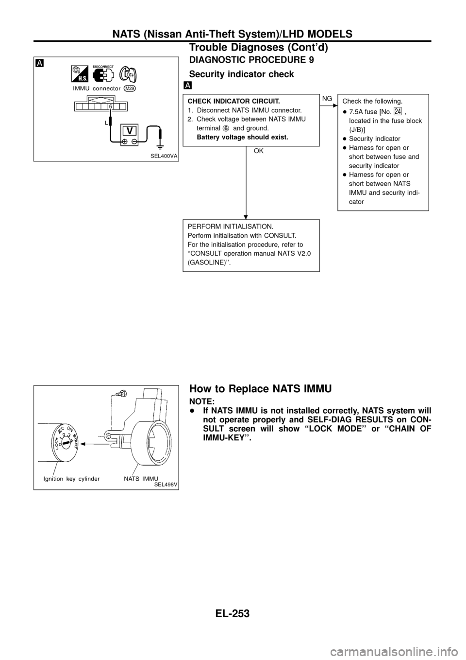
DIAGNOSTIC PROCEDURE 9
Security indicator check
CHECK INDICATOR CIRCUIT.
1. Disconnect NATS IMMU connector.
2. Check voltage between NATS IMMU
terminalj
6and ground.
Battery voltage should exist.
OK
cNG
Check the following.
+7.5A fuse [No.
24,
located in the fuse block
(J/B)]
+Security indicator
+Harness for open or
short between fuse and
security indicator
+Harness for open or
short between NATS
IMMU and security indi-
cator
PERFORM INITIALISATION.
Perform initialisation with CONSULT.
For the initialisation procedure, refer to
``CONSULT operation manual NATS V2.0
(GASOLINE)''.
How to Replace NATS IMMU
NOTE:
+If NATS IMMU is not installed correctly, NATS system will
not operate properly and SELF-DIAG RESULTS on CON-
SULT screen will show ``LOCK MODE'' or ``CHAIN OF
IMMU-KEY''.
SEL400VA
SEL498V
.
NATS (Nissan Anti-Theft System)/LHD MODELS
Trouble Diagnoses (Cont'd)
EL-253
Page 266 of 326
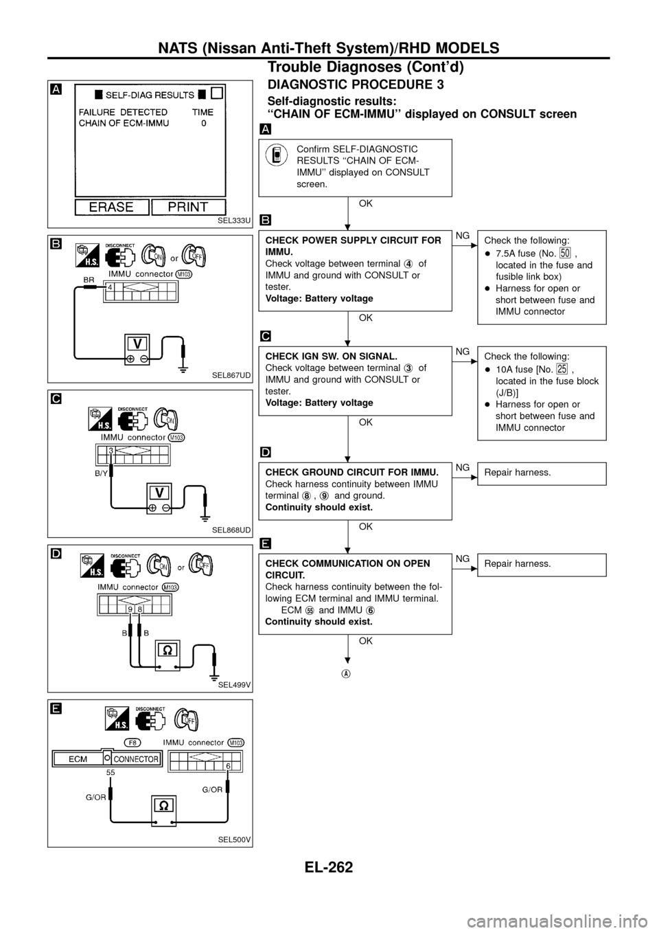
DIAGNOSTIC PROCEDURE 3
Self-diagnostic results:
``CHAIN OF ECM-IMMU'' displayed on CONSULT screen
Con®rm SELF-DIAGNOSTIC
RESULTS ``CHAIN OF ECM-
IMMU'' displayed on CONSULT
screen.
OK
CHECK POWER SUPPLY CIRCUIT FOR
IMMU.
Check voltage between terminalj
4of
IMMU and ground with CONSULT or
tester.
Voltage: Battery voltage
OK
cNG
Check the following:
+7.5A fuse (No.
50,
located in the fuse and
fusible link box)
+Harness for open or
short between fuse and
IMMU connector
CHECK IGN SW. ON SIGNAL.
Check voltage between terminalj
3of
IMMU and ground with CONSULT or
tester.
Voltage: Battery voltage
OK
cNG
Check the following:
+10A fuse [No.
25,
located in the fuse block
(J/B)]
+Harness for open or
short between fuse and
IMMU connector
CHECK GROUND CIRCUIT FOR IMMU.
Check harness continuity between IMMU
terminalj
8,j9and ground.
Continuity should exist.
OK
cNG
Repair harness.
CHECK COMMUNICATION ON OPEN
CIRCUIT.
Check harness continuity between the fol-
lowing ECM terminal and IMMU terminal.
ECMj
55and IMMUj6
Continuity should exist.
OK
cNG
Repair harness.
jA
SEL333U
SEL867UD
SEL868UD
SEL499V
SEL500V
.
.
.
.
.
NATS (Nissan Anti-Theft System)/RHD MODELS
Trouble Diagnoses (Cont'd)
EL-262
Page 271 of 326
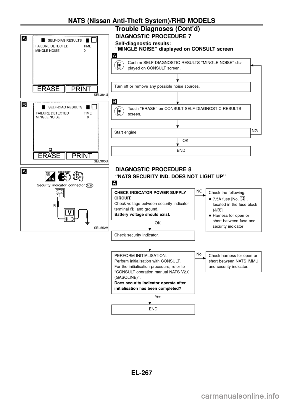
DIAGNOSTIC PROCEDURE 7
Self-diagnostic results:
``MINGLE NOISE'' displayed on CONSULT screen
Con®rm SELF-DIAGNOSTIC RESULTS ``MINGLE NOISE'' dis-
played on CONSULT screen.b
Turn off or remove any possible noise sources.
Touch ``ERASE'' on CONSULT SELF-DIAGNOSTIC RESULTS
screen.
Start engine.
OKNG
END
DIAGNOSTIC PROCEDURE 8
``NATS SECURITY IND. DOES NOT LIGHT UP''
CHECK INDICATOR POWER SUPPLY
CIRCUIT.
Check voltage between security indicator
terminalj
1and ground.
Battery voltage should exist.
OK
cNG
Check the following.
+7.5A fuse [No.
24,
located in the fuse block
(J/B)]
+Harness for open or
short between fuse and
security indicator
Check security indicator.
PERFORM INITIALISATION.
Perform initialisation with CONSULT.
For the initialisation procedure, refer to
``CONSULT operation manual NATS V2.0
(GASOLINE)''.
Does security indicator operate after
initialisation has been completed?
Ye s
cNo
Check harness for open or
short between NATS IMMU
and security indicator.
END
SEL384U
SEL385U
SEL552V
.
.
.
.
.
.
.
NATS (Nissan Anti-Theft System)/RHD MODELS
Trouble Diagnoses (Cont'd)
EL-267
Page 323 of 326
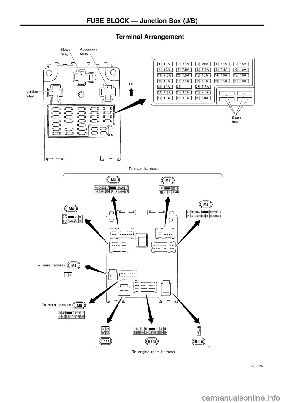
Terminal Arrangement
CEL775
FUSE BLOCK Ð Junction Box (J/B)