Check NISSAN PATROL 1998 Y61 / 5.G Electrical System Service Manual
[x] Cancel search | Manufacturer: NISSAN, Model Year: 1998, Model line: PATROL, Model: NISSAN PATROL 1998 Y61 / 5.GPages: 326, PDF Size: 11.36 MB
Page 168 of 326
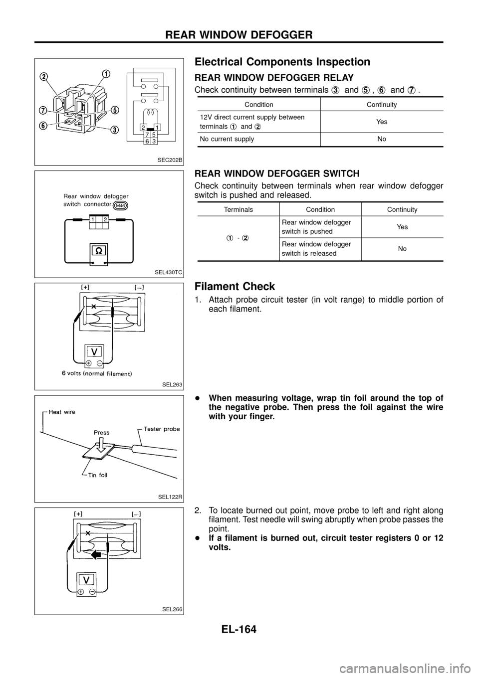
Electrical Components Inspection
REAR WINDOW DEFOGGER RELAY
Check continuity between terminalsj3andj5,j6andj7.
Condition Continuity
12V direct current supply between
terminalsj
1andj2Ye s
No current supply No
REAR WINDOW DEFOGGER SWITCH
Check continuity between terminals when rear window defogger
switch is pushed and released.
Terminals Condition Continuity
j
1-j2
Rear window defogger
switch is pushedYe s
Rear window defogger
switch is releasedNo
Filament Check
1. Attach probe circuit tester (in volt range) to middle portion of
each ®lament.
+When measuring voltage, wrap tin foil around the top of
the negative probe. Then press the foil against the wire
with your ®nger.
2. To locate burned out point, move probe to left and right along
®lament. Test needle will swing abruptly when probe passes the
point.
+If a ®lament is burned out, circuit tester registers 0 or 12
volts.
SEC202B
SEL430TC
SEL263
SEL122R
SEL266
REAR WINDOW DEFOGGER
EL-164
Page 169 of 326
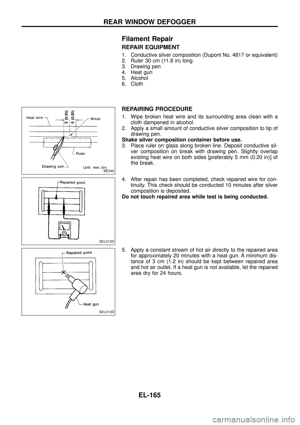
Filament Repair
REPAIR EQUIPMENT
1. Conductive silver composition (Dupont No. 4817 or equivalent)
2. Ruler 30 cm (11.8 in) long
3. Drawing pen
4. Heat gun
5. Alcohol
6. Cloth
REPAIRING PROCEDURE
1. Wipe broken heat wire and its surrounding area clean with a
cloth dampened in alcohol.
2. Apply a small amount of conductive silver composition to tip of
drawing pen.
Shake silver composition container before use.
3. Place ruler on glass along broken line. Deposit conductive sil-
ver composition on break with drawing pen. Slightly overlap
existing heat wire on both sides [preferably 5 mm (0.20 in)] of
the break.
4. After repair has been completed, check repaired wire for con-
tinuity. This check should be conducted 10 minutes after silver
composition is deposited.
Do not touch repaired area while test is being conducted.
5. Apply a constant stream of hot air directly to the repaired area
for approximately 20 minutes with a heat gun. A minimum dis-
tance of 3 cm (1.2 in) should be kept between repaired area
and hot air outlet. If a heat gun is not available, let the repaired
area dry for 24 hours.
BE540
SEL012D
SEL013D
REAR WINDOW DEFOGGER
EL-165
Page 176 of 326
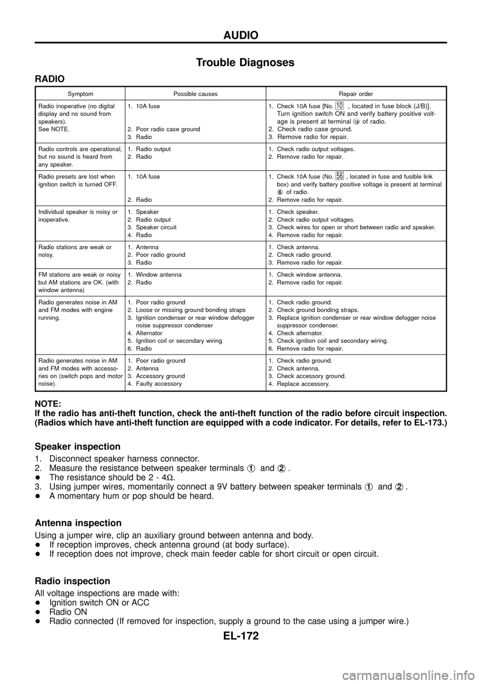
Trouble Diagnoses
RADIO
Symptom Possible causes Repair order
Radio inoperative (no digital
display and no sound from
speakers).
See NOTE.1. 10A fuse
2. Poor radio case ground
3. Radio1. Check 10A fuse [No.
10, located in fuse block (J/B)].
Turn ignition switch ON and verify battery positive volt-
age is present at terminalj
10of radio.
2. Check radio case ground.
3. Remove radio for repair.
Radio controls are operational,
but no sound is heard from
any speaker.1. Radio output
2. Radio1. Check radio output voltages.
2. Remove radio for repair.
Radio presets are lost when
ignition switch is turned OFF.1. 10A fuse
2. Radio1. Check 10A fuse (No.
56, located in fuse and fusible link
box) and verify battery positive voltage is present at terminal
j
6of radio.
2. Remove radio for repair.
Individual speaker is noisy or
inoperative.1. Speaker
2. Radio output
3. Speaker circuit
4. Radio1. Check speaker.
2. Check radio output voltages.
3. Check wires for open or short between radio and speaker.
4. Remove radio for repair.
Radio stations are weak or
noisy.1. Antenna
2. Poor radio ground
3. Radio1. Check antenna.
2. Check radio ground.
3. Remove radio for repair.
FM stations are weak or noisy
but AM stations are OK. (with
window antenna)1. Window antenna
2. Radio1. Check window antenna.
2. Remove radio for repair.
Radio generates noise in AM
and FM modes with engine
running.1. Poor radio ground
2. Loose or missing ground bonding straps
3. Ignition condenser or rear window defogger
noise suppressor condenser
4. Alternator
5. Ignition coil or secondary wiring
6. Radio1. Check radio ground.
2. Check ground bonding straps.
3. Replace ignition condenser or rear window defogger noise
suppressor condenser.
4. Check alternator.
5. Check ignition coil and secondary wiring.
6. Remove radio for repair.
Radio generates noise in AM
and FM modes with accesso-
ries on (switch pops and motor
noise).1. Poor radio ground
2. Antenna
3. Accessory ground
4. Faulty accessory1. Check radio ground.
2. Check antenna.
3. Check accessory ground.
4. Replace accessory.
NOTE:
If the radio has anti-theft function, check the anti-theft function of the radio before circuit inspection.
(Radios which have anti-theft function are equipped with a code indicator. For details, refer to EL-173.)
Speaker inspection
1. Disconnect speaker harness connector.
2. Measure the resistance between speaker terminalsj
1andj2.
+The resistance should be2-4W.
3. Using jumper wires, momentarily connect a 9V battery between speaker terminalsj
1andj2.
+A momentary hum or pop should be heard.
Antenna inspection
Using a jumper wire, clip an auxiliary ground between antenna and body.
+If reception improves, check antenna ground (at body surface).
+If reception does not improve, check main feeder cable for short circuit or open circuit.
Radio inspection
All voltage inspections are made with:
+Ignition switch ON or ACC
+Radio ON
+Radio connected (If removed for inspection, supply a ground to the case using a jumper wire.)
AUDIO
EL-172
Page 179 of 326
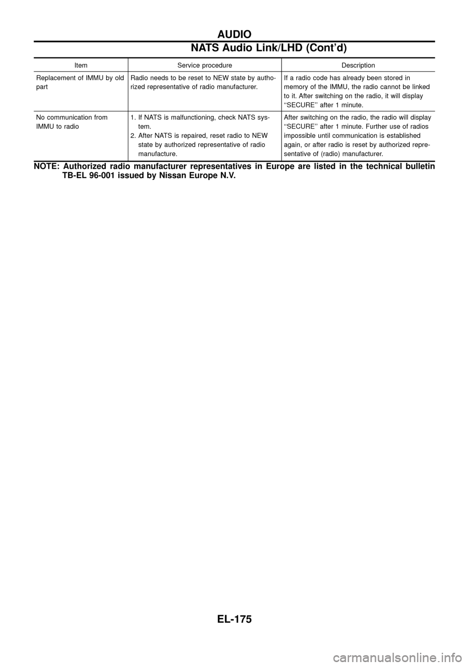
Item Service procedure Description
Replacement of IMMU by old
partRadio needs to be reset to NEW state by autho-
rized representative of radio manufacturer.If a radio code has already been stored in
memory of the IMMU, the radio cannot be linked
to it. After switching on the radio, it will display
``SECURE'' after 1 minute.
No communication from
IMMU to radio1. If NATS is malfunctioning, check NATS sys-
tem.
2. After NATS is repaired, reset radio to NEW
state by authorized representative of radio
manufacture.After switching on the radio, the radio will display
``SECURE'' after 1 minute. Further use of radios
impossible until communication is established
again, or after radio is reset by authorized repre-
sentative of (radio) manufacturer.
NOTE: Authorized radio manufacturer representatives in Europe are listed in the technical bulletin
TB-EL 96-001 issued by Nissan Europe N.V.
AUDIO
NATS Audio Link/LHD (Cont'd)
EL-175
Page 184 of 326
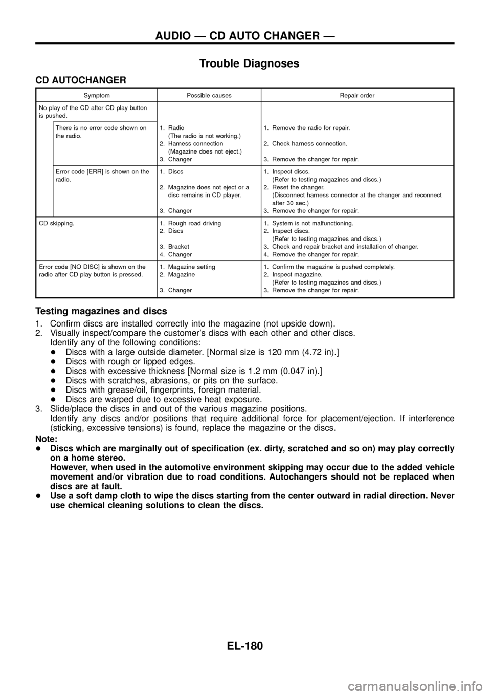
Trouble Diagnoses
CD AUTOCHANGER
Symptom Possible causes Repair order
No play of the CD after CD play button
is pushed.
There is no error code shown on
the radio.1. Radio
(The radio is not working.)
2. Harness connection
(Magazine does not eject.)
3. Changer1. Remove the radio for repair.
2. Check harness connection.
3. Remove the changer for repair.
Error code [ERR] is shown on the
radio.1. Discs
2. Magazine does not eject or a
disc remains in CD player.
3. Changer1. Inspect discs.
(Refer to testing magazines and discs.)
2. Reset the changer.
(Disconnect harness connector at the changer and reconnect
after 30 sec.)
3. Remove the changer for repair.
CD skipping. 1. Rough road driving
2. Discs
3. Bracket
4. Changer1. System is not malfunctioning.
2. Inspect discs.
(Refer to testing magazines and discs.)
3. Check and repair bracket and installation of changer.
4. Remove the changer for repair.
Error code [NO DISC] is shown on the
radio after CD play button is pressed.1. Magazine setting
2. Magazine
3. Changer1. Con®rm the magazine is pushed completely.
2. Inspect magazine.
(Refer to testing magazines and discs.)
3. Remove the changer for repair.
Testing magazines and discs
1. Con®rm discs are installed correctly into the magazine (not upside down).
2. Visually inspect/compare the customer's discs with each other and other discs.
Identify any of the following conditions:
+Discs with a large outside diameter. [Normal size is 120 mm (4.72 in).]
+Discs with rough or lipped edges.
+Discs with excessive thickness [Normal size is 1.2 mm (0.047 in).]
+Discs with scratches, abrasions, or pits on the surface.
+Discs with grease/oil, ®ngerprints, foreign material.
+Discs are warped due to excessive heat exposure.
3. Slide/place the discs in and out of the various magazine positions.
Identify any discs and/or positions that require additional force for placement/ejection. If interference
(sticking, excessive tensions) is found, replace the magazine or the discs.
Note:
+Discs which are marginally out of speci®cation (ex. dirty, scratched and so on) may play correctly
on a home stereo.
However, when used in the automotive environment skipping may occur due to the added vehicle
movement and/or vibration due to road conditions. Autochangers should not be replaced when
discs are at fault.
+Use a soft damp cloth to wipe the discs starting from the center outward in radial direction. Never
use chemical cleaning solutions to clean the discs.
AUDIO Ð CD AUTO CHANGER Ð
EL-180
Page 187 of 326
Trouble Diagnoses
POWER ANTENNA
Symptom Possible causes Repair order
Power antenna does not oper-
ate.1. 10A fuse
2. Radio signal
3. Grounds
E25andE40
1. Check 10A fuse (No.56, located in fuse and fusible link
box). Verify that battery positive voltage is present at termi-
nalj
1: LHD,j2: RHD of power antenna.
2. Turn ignition switch and radio ON. Verify that battery positive
voltage is present at terminalj
3: LHD,j1: RHD of power
antenna.
3. Check grounds
E25andE40.
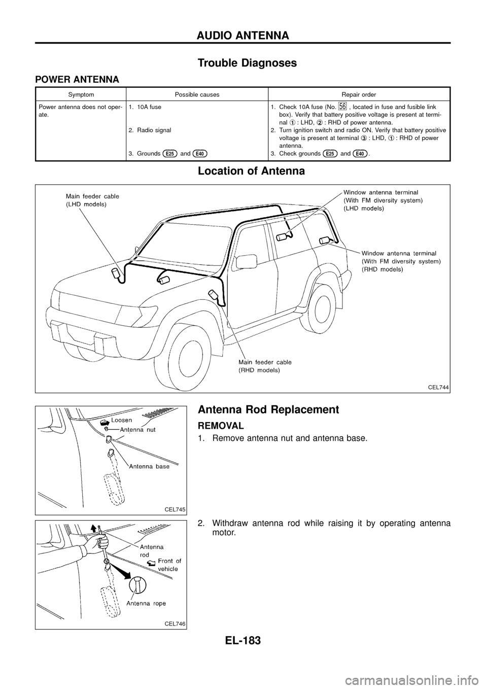
Location of Antenna
Antenna Rod Replacement
REMOVAL
1. Remove antenna nut and antenna base.
2. Withdraw antenna rod while raising it by operating antenna
motor.
CEL744
CEL745
CEL746
AUDIO ANTENNA
EL-183
Page 188 of 326
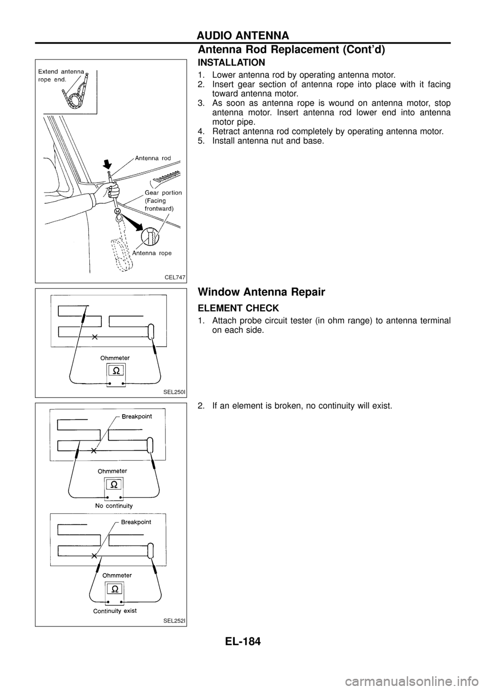
INSTALLATION
1. Lower antenna rod by operating antenna motor.
2. Insert gear section of antenna rope into place with it facing
toward antenna motor.
3. As soon as antenna rope is wound on antenna motor, stop
antenna motor. Insert antenna rod lower end into antenna
motor pipe.
4. Retract antenna rod completely by operating antenna motor.
5. Install antenna nut and base.
Window Antenna Repair
ELEMENT CHECK
1. Attach probe circuit tester (in ohm range) to antenna terminal
on each side.
2. If an element is broken, no continuity will exist.
CEL747
SEL250I
SEL252I
AUDIO ANTENNA
Antenna Rod Replacement (Cont'd)
EL-184
Page 207 of 326
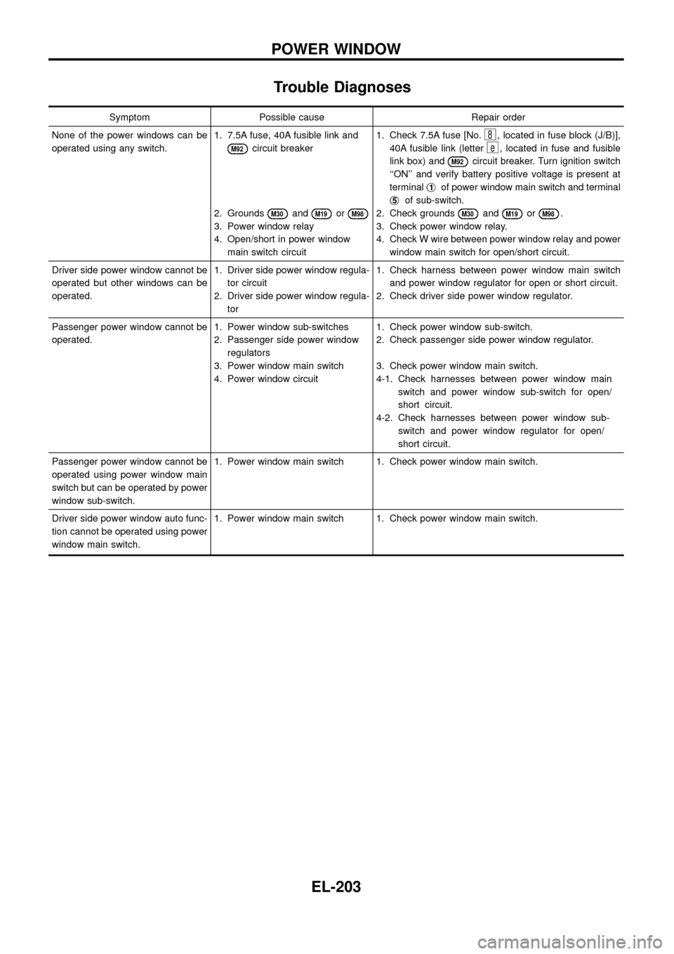
Trouble Diagnoses
Symptom Possible cause Repair order
None of the power windows can be
operated using any switch.1. 7.5A fuse, 40A fusible link and
M92circuit breaker
2. Grounds
M30andM19orM98
3. Power window relay
4. Open/short in power window
main switch circuit1. Check 7.5A fuse [No.
8, located in fuse block (J/B)],
40A fusible link (letter
e, located in fuse and fusible
link box) and
M92circuit breaker. Turn ignition switch
``ON'' and verify battery positive voltage is present at
terminalj
1of power window main switch and terminal
j
5of sub-switch.
2. Check grounds
M30andM19orM98.
3. Check power window relay.
4. Check W wire between power window relay and power
window main switch for open/short circuit.
Driver side power window cannot be
operated but other windows can be
operated.1. Driver side power window regula-
tor circuit
2. Driver side power window regula-
tor1. Check harness between power window main switch
and power window regulator for open or short circuit.
2. Check driver side power window regulator.
Passenger power window cannot be
operated.1. Power window sub-switches
2. Passenger side power window
regulators
3. Power window main switch
4. Power window circuit1. Check power window sub-switch.
2. Check passenger side power window regulator.
3. Check power window main switch.
4-1. Check harnesses between power window main
switch and power window sub-switch for open/
short circuit.
4-2. Check harnesses between power window sub-
switch and power window regulator for open/
short circuit.
Passenger power window cannot be
operated using power window main
switch but can be operated by power
window sub-switch.1. Power window main switch 1. Check power window main switch.
Driver side power window auto func-
tion cannot be operated using power
window main switch.1. Power window main switch 1. Check power window main switch.
POWER WINDOW
EL-203
Page 211 of 326
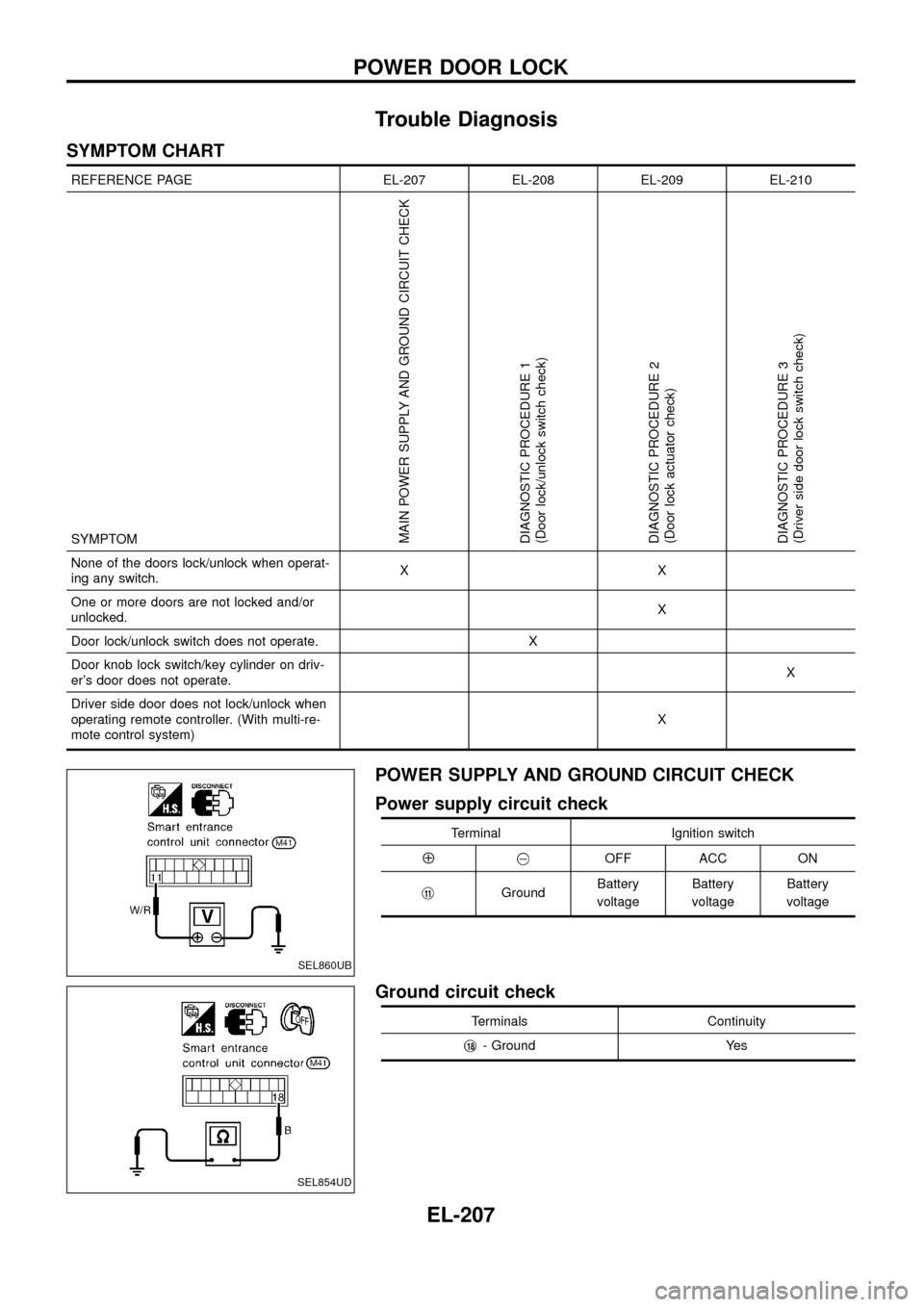
Trouble Diagnosis
SYMPTOM CHART
REFERENCE PAGE EL-207 EL-208 EL-209 EL-210
SYMPTOM
MAIN POWER SUPPLY AND GROUND CIRCUIT CHECK
DIAGNOSTIC PROCEDURE 1
(Door lock/unlock switch check)
DIAGNOSTIC PROCEDURE 2
(Door lock actuator check)
DIAGNOSTIC PROCEDURE 3
(Driver side door lock switch check)
None of the doors lock/unlock when operat-
ing any switch.XX
One or more doors are not locked and/or
unlocked.X
Door lock/unlock switch does not operate. X
Door knob lock switch/key cylinder on driv-
er's door does not operate.X
Driver side door does not lock/unlock when
operating remote controller. (With multi-re-
mote control system)X
POWER SUPPLY AND GROUND CIRCUIT CHECK
Power supply circuit check
Terminal Ignition switch
Å@OFF ACC ON
j
11GroundBattery
voltageBattery
voltageBattery
voltage
Ground circuit check
Terminals Continuity
j
18- Ground Yes
SEL860UB
SEL854UD
POWER DOOR LOCK
EL-207
Page 212 of 326
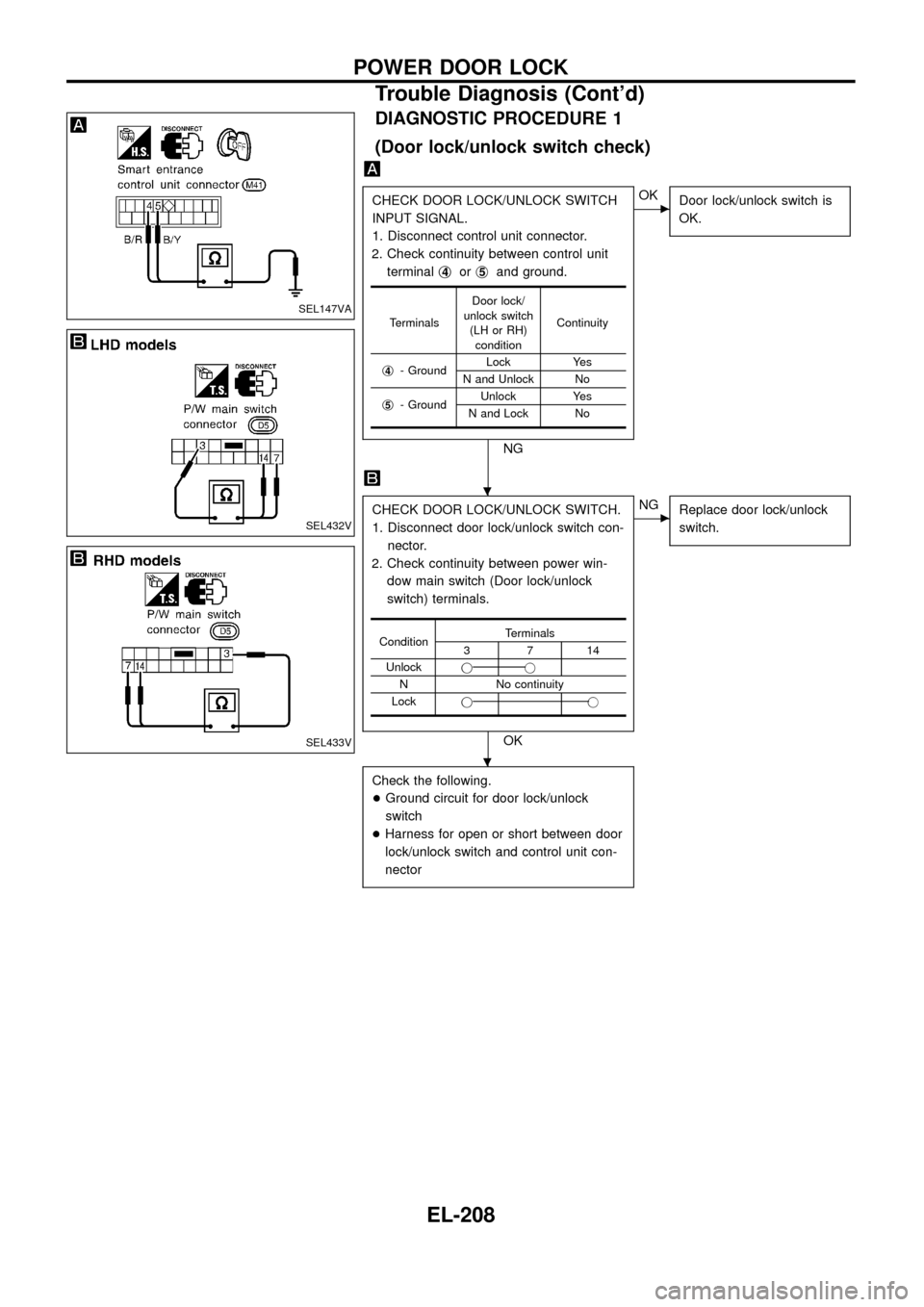
DIAGNOSTIC PROCEDURE 1
(Door lock/unlock switch check)
CHECK DOOR LOCK/UNLOCK SWITCH
INPUT SIGNAL.
1. Disconnect control unit connector.
2. Check continuity between control unit
terminalj
4orj5and ground.
NG
cOK
Door lock/unlock switch is
OK.
CHECK DOOR LOCK/UNLOCK SWITCH.
1. Disconnect door lock/unlock switch con-
nector.
2. Check continuity between power win-
dow main switch (Door lock/unlock
switch) terminals.
OK
cNG
Replace door lock/unlock
switch.
Check the following.
+Ground circuit for door lock/unlock
switch
+Harness for open or short between door
lock/unlock switch and control unit con-
nector
TerminalsDoor lock/
unlock switch
(LH or RH)
conditionContinuity
j
4- GroundLock Yes
N and Unlock No
j
5- GroundUnlock Yes
N and Lock No
ConditionTerminals3714
Unlockjj
N No continuity
Lockjj
SEL147VA
SEL432V
SEL433V
.
.
POWER DOOR LOCK
Trouble Diagnosis (Cont'd)
EL-208