gauge NISSAN PATROL 1998 Y61 / 5.G Electrical System Workshop Manual
[x] Cancel search | Manufacturer: NISSAN, Model Year: 1998, Model line: PATROL, Model: NISSAN PATROL 1998 Y61 / 5.GPages: 326, PDF Size: 11.36 MB
Page 2 of 326
Wiring Diagram Ð H/AIM Ð .....................................71
PARKING, LICENSE AND TAIL LAMPS......................73
Wiring Diagram Ð TAIL/L Ð/Type A .........................73
Wiring Diagram Ð TAIL/L Ð/Type B.........................75
STOP LAMP..................................................................77
Wiring Diagram Ð STOP/L Ð/Type A ......................77
BACK-UP LAMP............................................................78
Wiring Diagram Ð BACK/L Ð/LHD Models..............78
Wiring Diagram Ð BACK/L Ð/RHD Models .............79
REAR FOG LAMP.........................................................80
Wiring Diagram Ð R/FOG Ð ....................................80
TURN SIGNAL AND HAZARD WARNING LAMPS.....81
Wiring Diagram Ð TURN Ð/Type A .........................81
Wiring Diagram Ð TURN Ð/Type B .........................83
Trouble Diagnoses.....................................................85
Electrical Components Inspection .............................85
ILLUMINATION..............................................................86
Schematic ..................................................................86
Wiring Diagram Ð ILL Ð ..........................................87
INTERIOR ROOM LAMP Ð With Timer Ð.................93
System Description ....................................................93
Schematic ..................................................................94
Wiring Diagram Ð ROOM/L Ð/LHD Models ............95
Wiring Diagram Ð ROOM/L Ð/RHD Models............98
Trouble Diagnoses...................................................100
MAP AND VANITY MIRROR LAMPS.........................101
Wiring Diagram Ð INT/L Ð.....................................101
METER AND GAUGES...............................................102
System Description ..................................................102
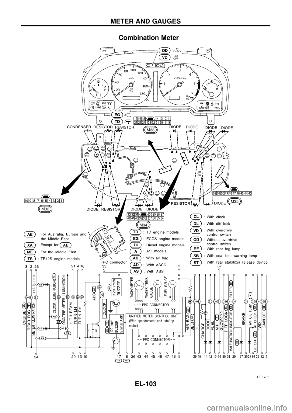
Combination Meter ..................................................103
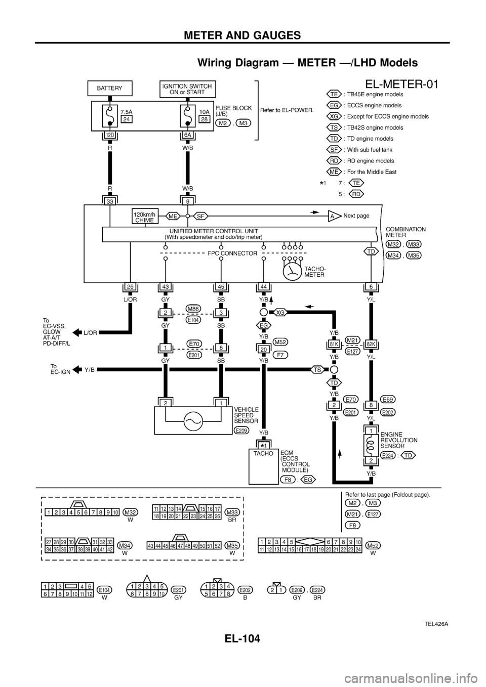
Wiring Diagram Ð METER Ð/LHD Models............104
Wiring Diagram Ð METER Ð/RHD Models ...........106
Meter/Gauge Operation and Odo/Trip Meter
Segment Check in Diagnosis Mode ........................108
Flexible Print Circuit (FPC) ......................................109
Trouble Diagnoses................................................... 110
Electrical Components Inspection ........................... 114
COMPASS AND THERMOMETER............................. 116
System Description .................................................. 116
Wiring Diagram Ð COMPAS Ð .............................. 117
Trouble Diagnoses................................................... 118
Calibration Procedure For Compass ....................... 119
WARNING LAMPS......................................................121
Schematic ................................................................121
Wiring Diagram Ð WARN Ð ..................................123
Electrical Components Inspection ...........................134
WARNING CHIME.......................................................135
System Description ..................................................135
Wiring Diagram Ð CHIME Ð/LHD Models.............136
Wiring Diagram Ð CHIME Ð/RHD Models ............137
Trouble Diagnoses...................................................138
Electrical Components Inspection ...........................140FRONT WIPER AND WASHER..................................141
System Description ..................................................141
Wiring Diagram Ð WIPER Ð/With Intermittent
Wiper........................................................................142
Removal and Installation .........................................143
Washer Nozzle Adjustment .....................................144
Washer Tube Layout ...............................................144
REAR WIPER AND WASHER....................................145
System Description ..................................................145
Wiring Diagram Ð WIP/R Ð/LHD Models ..............146
Wiring Diagram Ð WIP/R Ð/RHD Models .............148
Trouble Diagnoses...................................................150
Removal and Installation .........................................151
Washer Nozzle Adjustment .....................................151
Washer Tube Layout ...............................................152
Check Valve .............................................................152
HEADLAMP WIPER AND WASHER..........................153
Wiring Diagram Ð HLC Ð ......................................153
Electrical Components Inspection ...........................154
Removal and Installation .........................................154
Washer Tube Layout ...............................................154
Check Valve .............................................................154
HORN...........................................................................155
Wiring Diagram Ð HORN Ð...................................155
CIGARETTE LIGHTER................................................156
Wiring Diagram Ð CIGAR Ð ..................................156
CLOCK.........................................................................157
Wiring Diagram Ð CLOCK Ð .................................157
REAR WINDOW DEFOGGER.....................................158
System Description ..................................................158
Wiring Diagram Ð DEF Ð/LHD Models .................159
Wiring Diagram Ð DEF Ð/RHD Models ................161
Trouble Diagnoses...................................................163
Electrical Components Inspection ...........................164
Filament Check ........................................................164
Filament Repair .......................................................165
WIPER DEICER...........................................................166
System Description ..................................................166
Wiring Diagram Ð DEICER Ð................................167
AUDIO..........................................................................168
Wiring Diagram Ð AUDIO Ð/LHD Models .............168
Wiring Diagram Ð AUDIO Ð/RHD Models ............170
Trouble Diagnoses...................................................172
CATS (Code) System/RHD .....................................173
NATS Audio Link/LHD .............................................174
AUDIO Ð CD AUTO CHANGER Ð...........................176
Wiring Diagram Ð CD/CHG Ð/LHD Wagon ..........176
Wiring Diagram Ð CD/CHG Ð/LHD Hardtop .........177
Wiring Diagram Ð CD/CHG Ð/RHD Wagon ..........178
Wiring Diagram Ð CD/CHG Ð/RHD Hardtop ........179
Trouble Diagnoses...................................................180
AUDIO ANTENNA.......................................................181
Page 106 of 326
System Description
UNIFIED CONTROL METER
+Speedometer, odo/trip meter, tachometer, fuel gauge and water temperature gauge are controlled totally
by control unit combined with speedometer.
+Digital meter is adopted for odo/trip meter.*
*The record of the odo meter is kept even if the battery cable is disconnected. The record of the trip meter
is erased when the battery cable is disconnected.
+Odo/trip meter segment can be checked in diagnosis mode.
+Meter/gauge can be checked in diagnosis mode.
Note: Sub fuel gauge is not controlled by the control unit.
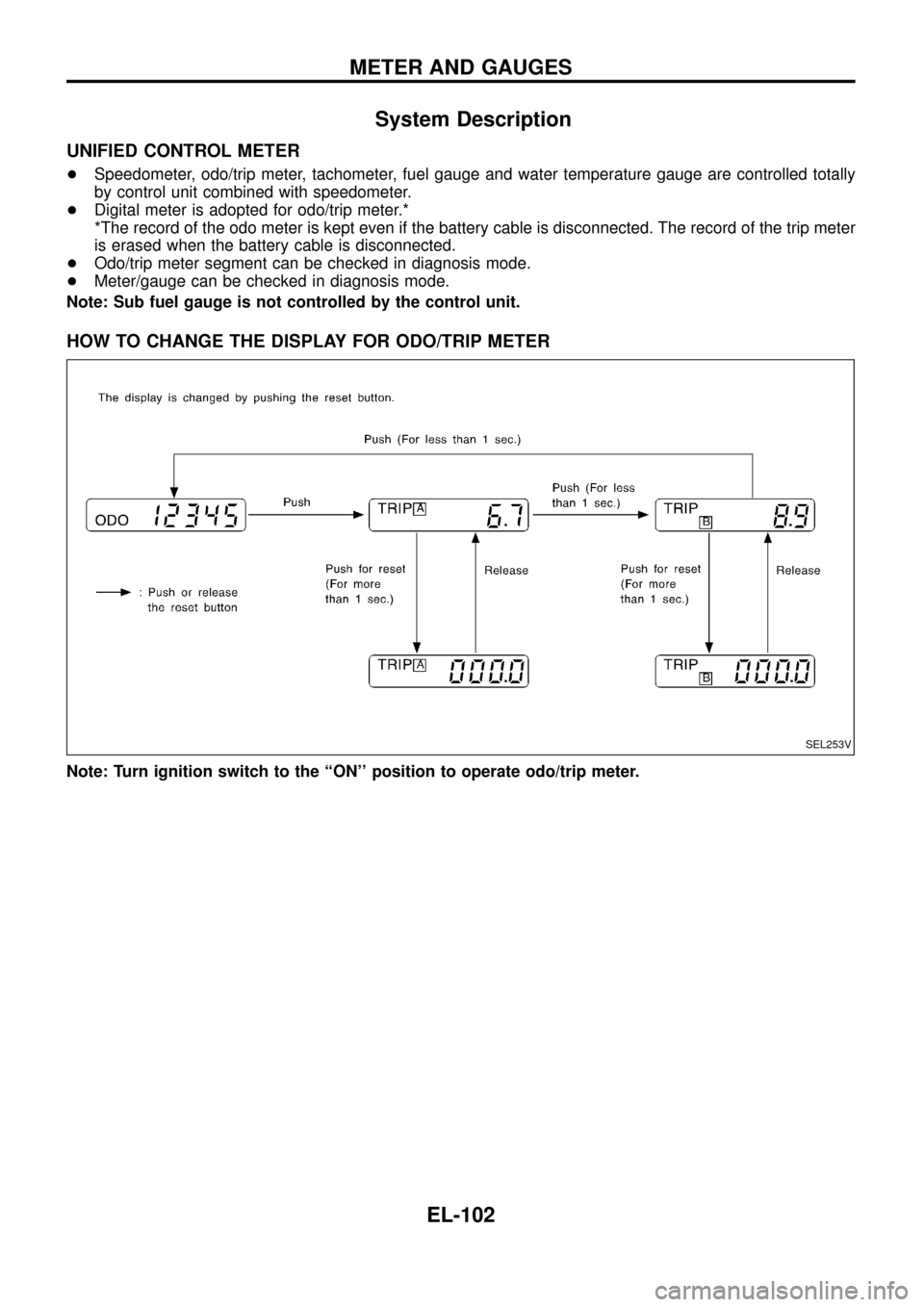
HOW TO CHANGE THE DISPLAY FOR ODO/TRIP METER
Note: Turn ignition switch to the ``ON'' position to operate odo/trip meter.
SEL253V
METER AND GAUGES
EL-102
Page 107 of 326
Combination Meter
CEL785
METER AND GAUGES
EL-103
Page 108 of 326
Wiring Diagram Ð METER Ð/LHD Models
TEL426A
METER AND GAUGES
EL-104
Page 109 of 326
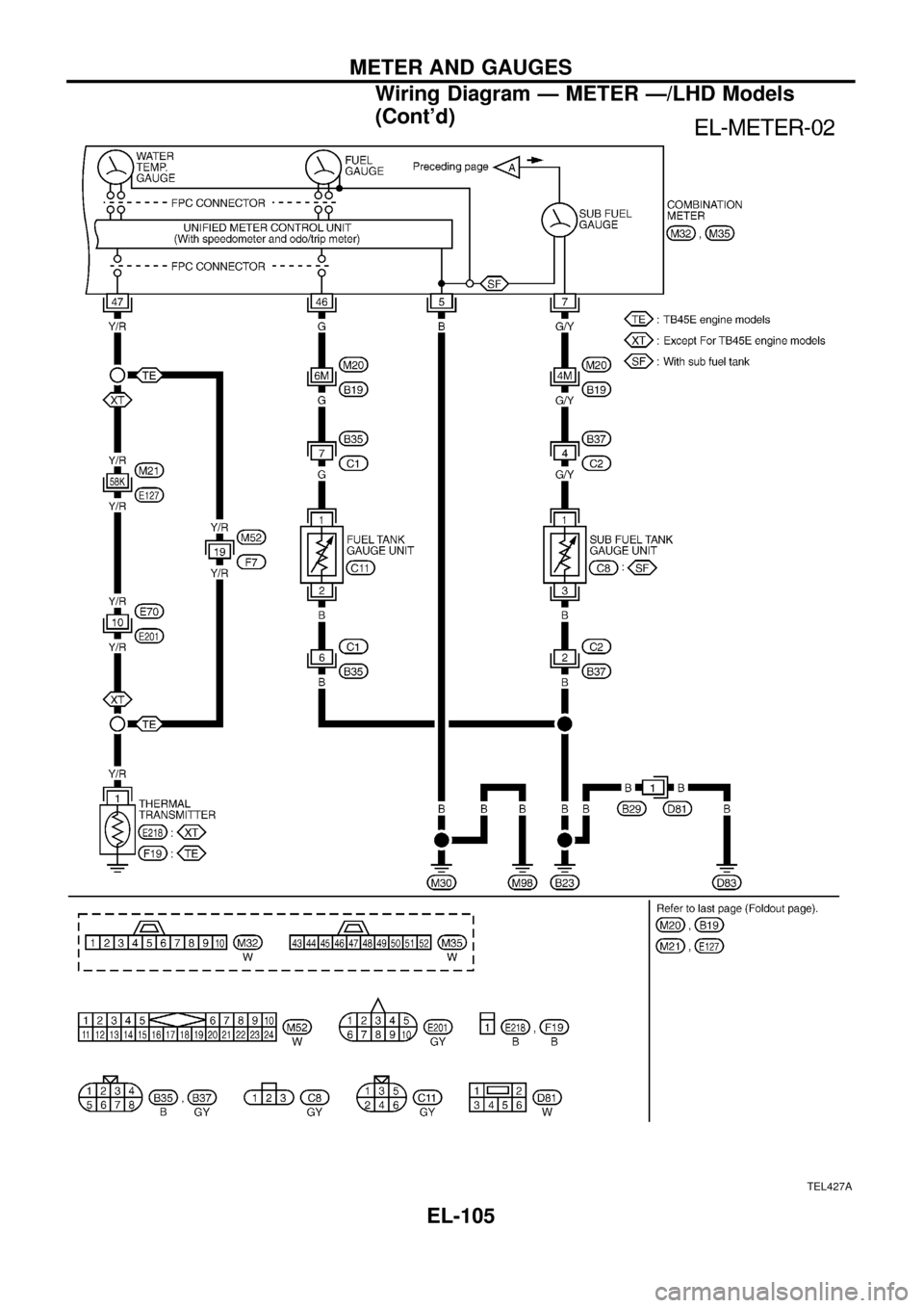
TEL427A
METER AND GAUGES
Wiring Diagram Ð METER Ð/LHD Models
(Cont'd)
EL-105
Page 110 of 326
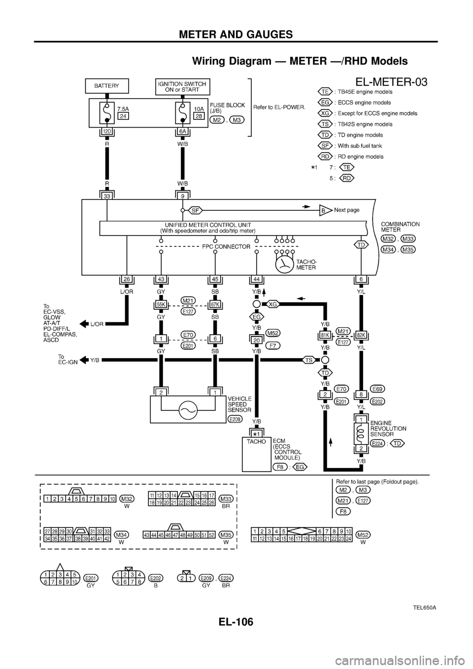
Wiring Diagram Ð METER Ð/RHD Models
TEL650A
METER AND GAUGES
EL-106
Page 111 of 326
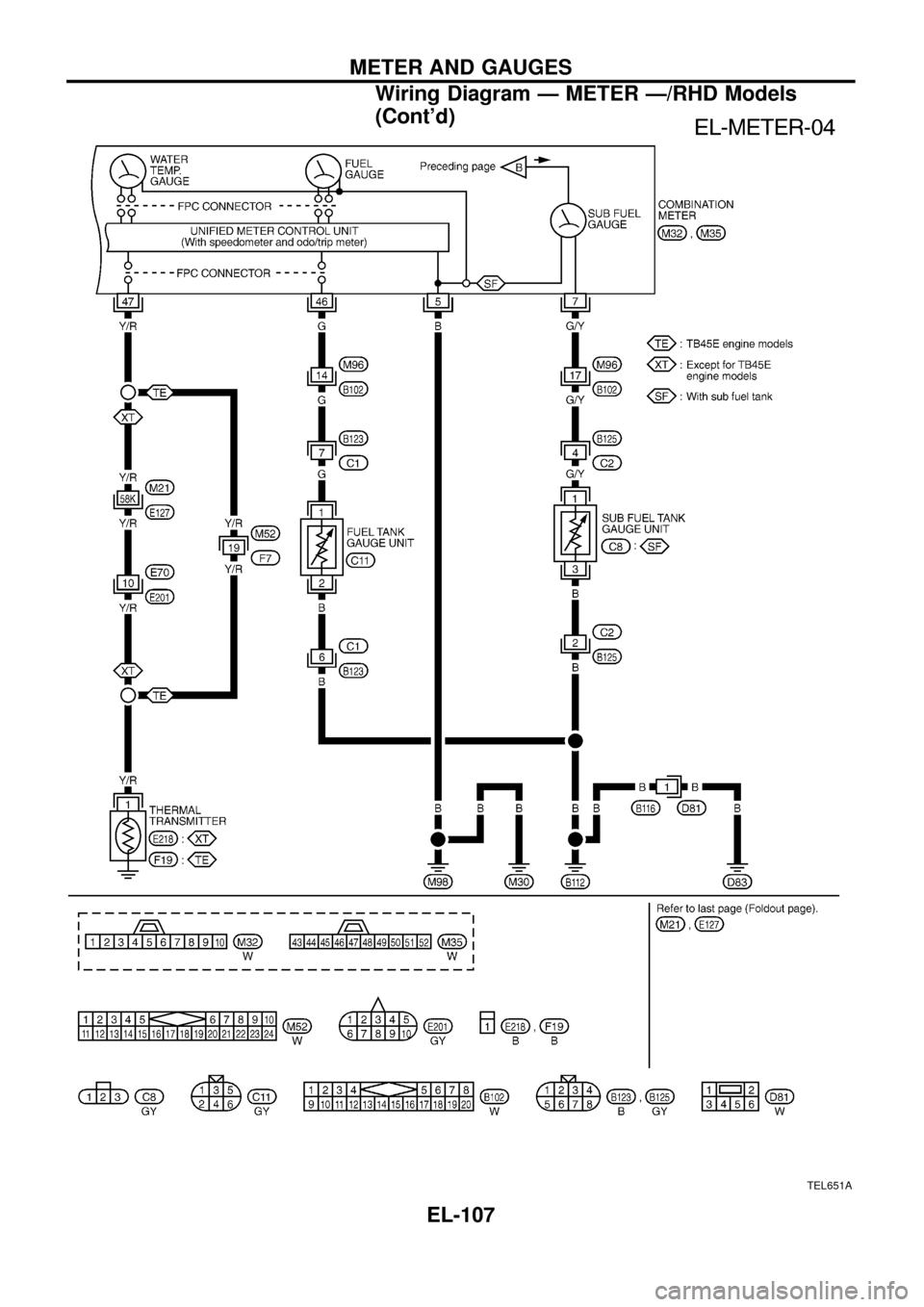
TEL651A
METER AND GAUGES
Wiring Diagram Ð METER Ð/RHD Models
(Cont'd)
EL-107
Page 112 of 326
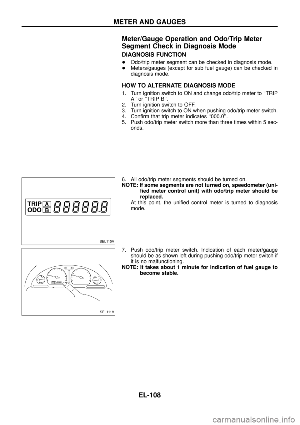
Meter/Gauge Operation and Odo/Trip Meter
Segment Check in Diagnosis Mode
DIAGNOSIS FUNCTION
+Odo/trip meter segment can be checked in diagnosis mode.
+Meters/gauges (except for sub fuel gauge) can be checked in
diagnosis mode.
HOW TO ALTERNATE DIAGNOSIS MODE
1. Turn ignition switch to ON and change odo/trip meter to ``TRIP
A'' or ``TRIP B''.
2. Turn ignition switch to OFF.
3. Turn ignition switch to ON when pushing odo/trip meter switch.
4. Con®rm that trip meter indicates ``000.0''.
5. Push odo/trip meter switch more than three times within 5 sec-
onds.
6. All odo/trip meter segments should be turned on.
NOTE: If some segments are not turned on, speedometer (uni-
®ed meter control unit) with odo/trip meter should be
replaced.
At this point, the uni®ed control meter is turned to diagnosis
mode.
7. Push odo/trip meter switch. Indication of each meter/gauge
should be as shown left during pushing odo/trip meter switch if
it is no malfunctioning.
NOTE: It takes about 1 minute for indication of fuel gauge to
become stable.
SEL110V
SEL111V
METER AND GAUGES
EL-108
Page 113 of 326
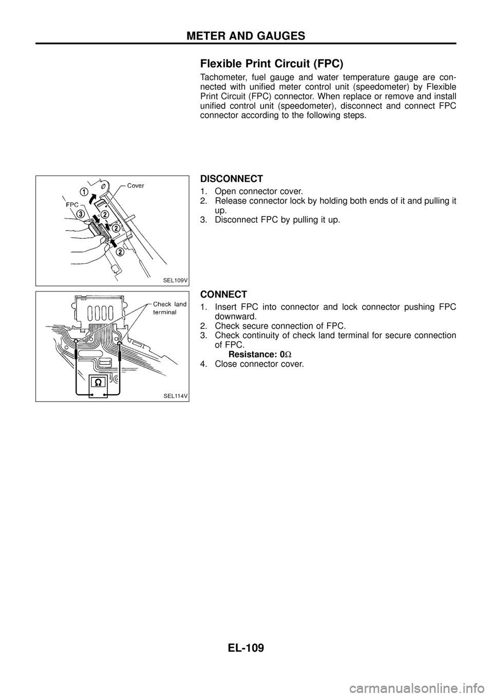
Flexible Print Circuit (FPC)
Tachometer, fuel gauge and water temperature gauge are con-
nected with uni®ed meter control unit (speedometer) by Flexible
Print Circuit (FPC) connector. When replace or remove and install
uni®ed control unit (speedometer), disconnect and connect FPC
connector according to the following steps.
DISCONNECT
1. Open connector cover.
2. Release connector lock by holding both ends of it and pulling it
up.
3. Disconnect FPC by pulling it up.
CONNECT
1. Insert FPC into connector and lock connector pushing FPC
downward.
2. Check secure connection of FPC.
3. Check continuity of check land terminal for secure connection
of FPC.
Resistance: 0W
4. Close connector cover.
SEL109V
SEL114V
METER AND GAUGES
EL-109
Page 114 of 326
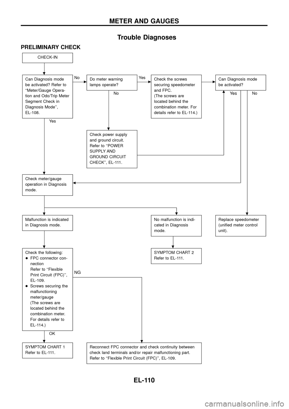
Trouble Diagnoses
PRELIMINARY CHECK
CHECK-IN
Can Diagnosis mode
be activated? Refer to
``Meter/Gauge Opera-
tion and Odo/Trip Meter
Segment Check in
Diagnosis Mode'',
EL-108.
Ye s
cNo
Do meter warning
lamps operate?
No
cYe s
Check the screws
securing speedometer
and FPC.
(The screws are
located behind the
combination meter. For
details refer to EL-114.)cCan Diagnosis mode
be activated?
Nom
Check power supply
and ground circuit.
Refer to ``POWER
SUPPLY AND
GROUND CIRCUIT
CHECK'', EL-111.
Check meter/gauge
operation in Diagnosis
mode.b
Ye s
.
Malfunction is indicated
in Diagnosis mode.No malfunction is indi-
cated in Diagnosis
mode.Replace speedometer
(uni®ed meter control
unit).
Check the following:
+FPC connector con-
nection
Refer to ``Flexible
Print Circuit (FPC)'',
EL-109.
+Screws securing the
malfunctioning
meter/gauge
(The screws are
located behind the
combination meter.
For details refer to
EL-114.)
OK
.
NG
SYMPTOM CHART 2
Refer to EL-111.
SYMPTOM CHART 1
Refer to EL-111.Reconnect FPC connector and check continuity between
check land terminals and/or repair malfunctioning part.
Refer to ``Flexible Print Circuit (FPC)'', EL-109.
.
.
.
..
..
.
METER AND GAUGES
EL-110