service NISSAN PATROL 1998 Y61 / 5.G Engine Control Workshop Manual
[x] Cancel search | Manufacturer: NISSAN, Model Year: 1998, Model line: PATROL, Model: NISSAN PATROL 1998 Y61 / 5.GPages: 192, PDF Size: 4.28 MB
Page 1 of 192
ENGINE CONTROL SYSTEMSECTION
EC
CONTENTS
DIAGNOSTIC TROUBLE CODE INDEX .........................1
Alphabetical & Numerical Index for DTC ....................1
PRECAUTIONS AND PREPARATION ............................2
Special Service Tools ..................................................2
Commercial Service Tool .............................................3
Supplemental Restraint System (SRS) ``AIR
BAG'' and ``SEAT BELT PRE-TENSIONER''...............4
PRECAUTIONS AND PREPARATION ............................5
Engine Fuel & Emission Control System ....................5
Precautions ..................................................................6
ENGINE AND EMISSION CONTROL OVERALL
SYSTEM ........................................................................\
...8
ECCS-D Component Parts Location ...........................8
Circuit Diagram .......................................................... 11
System Diagram ........................................................12
Vacuum Hose Drawing ..............................................13
System Chart .............................................................14
ENGINE AND EMISSION BASIC CONTROL
SYSTEM DESCRIPTION ...............................................15
Fuel Injection System ................................................15
Fuel Injection Timing System ....................................18
Air Conditioning Cut Control ......................................19
Fuel Cut Control (at no load & high engine
speed) ........................................................................\
20
CRANKCASE VENTILATION SYSTEM ........................21
Description .................................................................21
Inspection...................................................................21
INJECTION NOZZLE .....................................................22
Removal and Installation ...........................................22
Disassembly (No. 2 - 4 nozzles) ...............................22
Inspection (No. 2 - 4 nozzles) ...................................23
Cleaning (No. 2 - 4 nozzles) .....................................23
Assembly (No. 2 - 4 nozzles) ....................................24
Test and Adjustment ..................................................25
ELECTRONIC FUEL INJECTION PUMP ......................27
Removal .....................................................................27
Installation ..................................................................28
Disassembly and Assembly .......................................29
ON BOARD DIAGNOSTIC SYSTEM
DESCRIPTION ...............................................................30
DTC and MIL Detection Logic ...................................30
Diagnostic Trouble Code (DTC) ................................30 Malfunction Indicator Lamp (MIL) ..............................31
CONSULT ..................................................................36
TROUBLE DIAGNOSIS Ð Introduction ......................42
Introduction ................................................................42
Diagnostic Worksheet ................................................43
TROUBLE DIAGNOSIS Ð Work Flow ........................44
Work Flow ..................................................................44
Description for Work Flow .........................................45
TROUBLE DIAGNOSIS Ð Basic Inspection ..............46
Basic Inspection.........................................................46
TROUBLE DIAGNOSIS Ð General Description ........48
Symptom Matrix Chart ...............................................48
CONSULT Reference Value in Data Monitor
Mode ........................................................................\
..51
Major Sensor Reference Graph in Data Monitor
Mode ........................................................................\
..53
ECM Terminals and Reference Value .......................54
TROUBLEDIAGNOSISFORPOWERSUPPLY ..........63
MainPowerSupplyandGroundCircuit....................63
TROUBLE DIAGNOSIS FOR ``CAM POS SEN
(PUMP)''(DTC11) .........................................................69
CamshaftPositionSensor(CMPS)(PUMP).............69
TROUBLEDIAGNOSISFOR``MASSAIRFLOW
SEN''(DTC12) ..............................................................74
MassAirFlowSensor(MAFS)..................................74
TROUBLEDIAGNOSISFOR``COOLANTTEMP
SEN''(DTC13) ..............................................................79
EngineCoolantTemperature(ECT)Sensor.............79
TROUBLEDIAGNOSISFOR``VEHICLESPEED
SEN''(DTC14) ..............................................................83
VehicleSpeedSensor(VSS)....................................83
TROUBLEDIAGNOSISFOR``CONTSLEEVPOS
SEN''(DTC15) ..............................................................87
ControlSleevePositionSensor(CSPS)...................87
TROUBLEDIAGNOSISFOR``ADJUST
RESISTOR''(DTC17) ...................................................92
AdjustmentResistor...................................................92
TROUBLEDIAGNOSISFOR``F/INJF/B2''
(DTC18),``F/INJF/B''(DTC22),``ELECTRIC
GOV''(DTC25) ..............................................................96
ElectricGovernor.......................................................96
EC
Page 2 of 192
TROUBLEDIAGNOSISFOR``F/INJTIMGF/B''
(DTC21).......................................................................101
InjectionTimingControlValve.................................101
TROUBLEDIAGNOSISFOR``ACCELPOSSW
(F/C)''(DTC23) ...........................................................106
AcceleratorSwitch(F/C)..........................................106
TROUBLEDIAGNOSISFOR``ECM1''(DTC27),
``ECM2''(DTC31) .......................................................111
EngineControlModule(ECM)-ECCS-DControl
Module.....................................................................111
TROUBLEDIAGNOSISFOR``OVERHEAT''
(DTC28) .......................................................................113
CoolingFan(Overheat)...........................................113
TROUBLEDIAGNOSISFOR``I/CINT/ATEMP
SEN''(DTC33) ............................................................122
ChargeAirTemperatureSensor..............................122
TROUBLEDIAGNOSISFOR``NEEDLELIFT
SEN''(DTC34) ............................................................126
NeedleLiftSensor(NLS)........................................126
TROUBLE DIAGNOSIS FOR ``FUEL CUT S/V 1''
(DTC 36), ``FCV SHORT'' (DTC 37), ``FUEL CUT
S/V2''(DTC38) ...........................................................130
FuelCutSolenoidValve..........................................130
TROUBLE DIAGNOSIS FOR ``FUEL TEMP
SENSOR''(DTC42) ....................................................135
FuelTemperatureSensor(FTS)..............................135 TROUBLE DIAGNOSIS FOR ``ACCEL POS
SENSOR''(DTC43)
....................................................139
AcceleratorPositionSensor....................................139
TROUBLE DIAGNOSIS FOR ``CRANK POS SEN
(TDC)''(DTC47) ..........................................................144
CrankshaftPositionSensor(TDC)..........................144
TROUBLEDIAGNOSISFOR``GOVCUT
CIRCUIT''(DTC48) .....................................................149
GovernorCutCircuit................................................149
TROUBLEDIAGNOSESFORNON-DETECTABLE
ITEMS ........................................................................\
...151
GlowControlSystem...............................................151
EGRC-SolenoidValveA,BandThrottleControl
SolenoidValve.........................................................156
StartSignal..............................................................163
AcceleratorPositionSwitch.....................................165
Park/NeutralPositionSwitch...................................170
A/TControl...............................................................175
ChargeAirCoolerFanControl................................178
HeatUpSwitch........................................................183
AirConditionerControl............................................187
MIL&DataLinkConnectors...................................188
SERVICEDATAANDSPECIFICATIONS(SDS) ........189
GeneralSpeci®cations.............................................189
InjectionNozzle.......................................................189
InspectionandAdjustment......................................189
When you read wiring diagrams:
+ Read GI section, ``HOW TO READ WIRING DIAGRAMS''.
+ See EL section, ``POWER SUPPLY ROUTING'' for power distribution circuit.
When you perform trouble diagnoses, read GI section, ``HOW TO FOLLOW FLOW CHART IN
TROUBLE DIAGNOSES'' and ``HOW TO PERFORM EFFICIENT DIAGNOSIS FOR AN ELECTRICAL
INCIDENT''.
Page 4 of 192
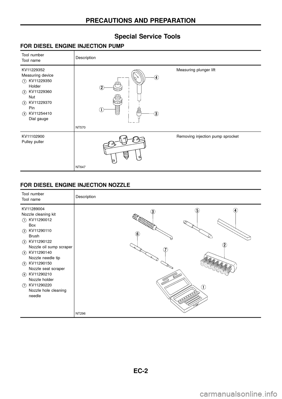
Special Service Tools
FOR DIESEL ENGINE INJECTION PUMP
Tool number
Tool nameDescription
KV11229352
Measuring device
V1KV11229350
Holder
V2KV11229360
Nut
V3KV11229370
Pin
V4KV11254410
Dial gauge
NT570
Measuring plunger lift
KV11102900
Pulley puller
NT647
Removing injection pump sprocket
FOR DIESEL ENGINE INJECTION NOZZLE
Tool number
Tool nameDescription
KV11289004
Nozzle cleaning kit
V1KV11290012
Box
V2KV11290110
Brush
V3KV11290122
Nozzle oil sump scraper
V4KV11290140
Nozzle needle tip
V5KV11290150
Nozzle seat scraper
V6KV11290210
Nozzle holder
V7KV11290220
Nozzle hole cleaning
needle
NT296
PRECAUTIONS AND PREPARATION
EC-2
Page 5 of 192
Tool number
Tool nameDescription
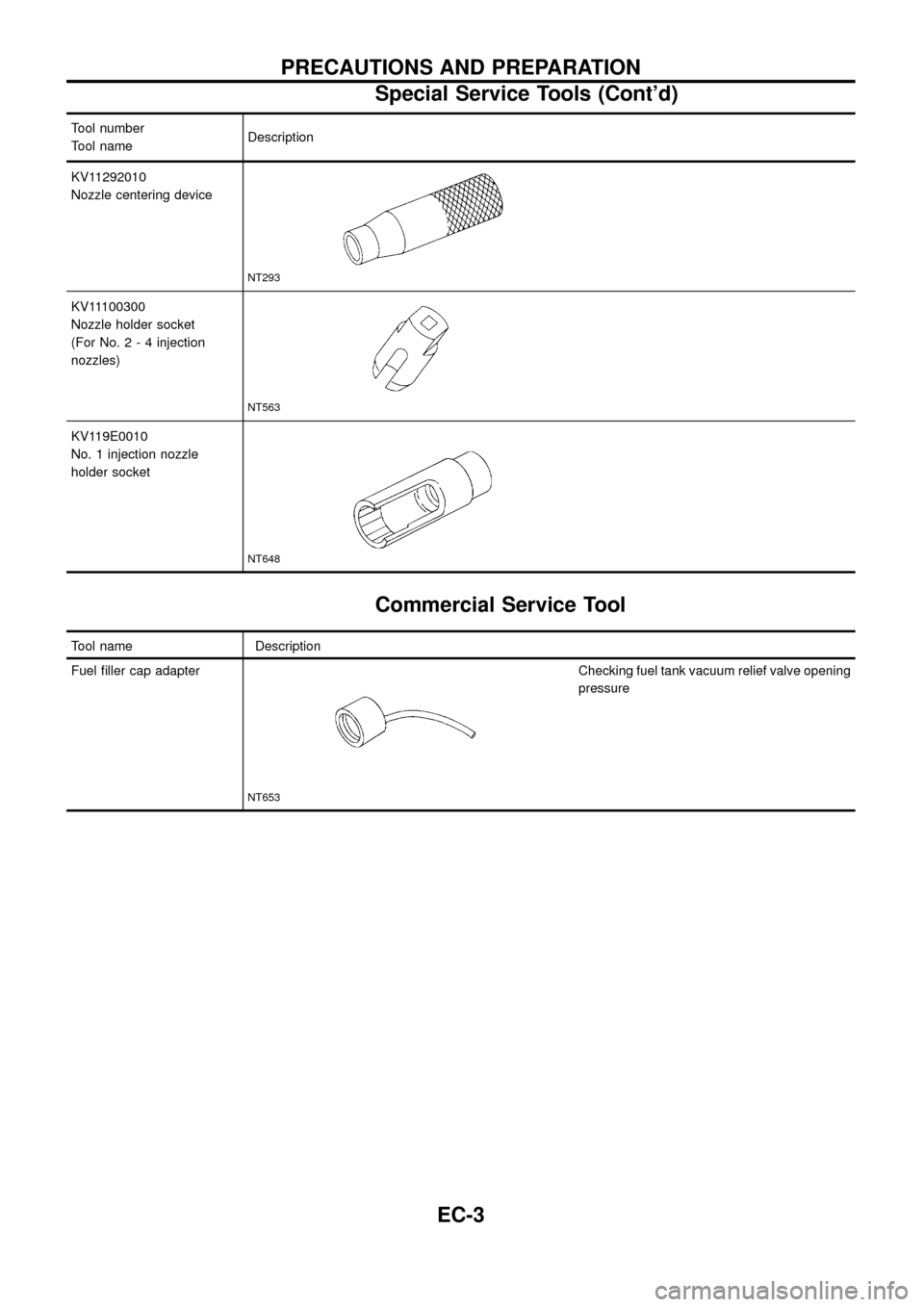
KV11292010
Nozzle centering device
NT293
KV11100300
Nozzle holder socket
(For No.2-4injection
nozzles)
NT563
KV119E0010
No. 1 injection nozzle
holder socket
NT648
Commercial Service Tool
Tool name Description
Fuel ®ller cap adapter
NT653
Checking fuel tank vacuum relief valve opening
pressure
PRECAUTIONS AND PREPARATION
Special Service Tools (Cont'd)
EC-3
Page 6 of 192
Supplemental Restraint System (SRS) ``AIR
BAG'' and ``SEAT BELT PRE-TENSIONER''
The Supplemental Restraint System such as ``AIR BAG'' and ``SEAT BELT PRE-TENSIONER'' used along with
a seat belt, helps to reduce the risk or severity of injury to the driver and front passenger in a frontal collision.
The SRS system composition which is available to NISSAN MODEL Y61 is as follows (The composition var-
ies according to the destination.):
Driver air bag module (located in the center of the steering wheel), front passenger air bag module (located
on the instrument panel on passenger side), seat belt pre-tensioner, a diagnosis sensor unit, warning lamp,
wiring harness and spiral cable.
Information necessary to service the system safely is included in theRS sectionof this Service Manual.
WARNING:
+To avoid rendering the SRS inoperative, which could increase the risk of personal injury or death
in the event of a collision which would result in air bag in¯ation, all maintenance must be performed
by an authorized NISSAN dealer.
+Improper maintenance, including incorrect removal and installation of the SRS, can lead to per-
sonal injury caused by unintentional activation of the system. For removal of Spiral Cable and Air
Bag Module, see the RS section.
+Do not use electrical test equipment on any circuit related to the SRS unless instructed to in this
Service Manual. Spiral cable and wiring harnesses covered with yellow insulation either just before
the harness connectors or for the complete harness are related to the SRS.
PRECAUTIONS AND PREPARATION
EC-4
Page 38 of 192
CONSULT
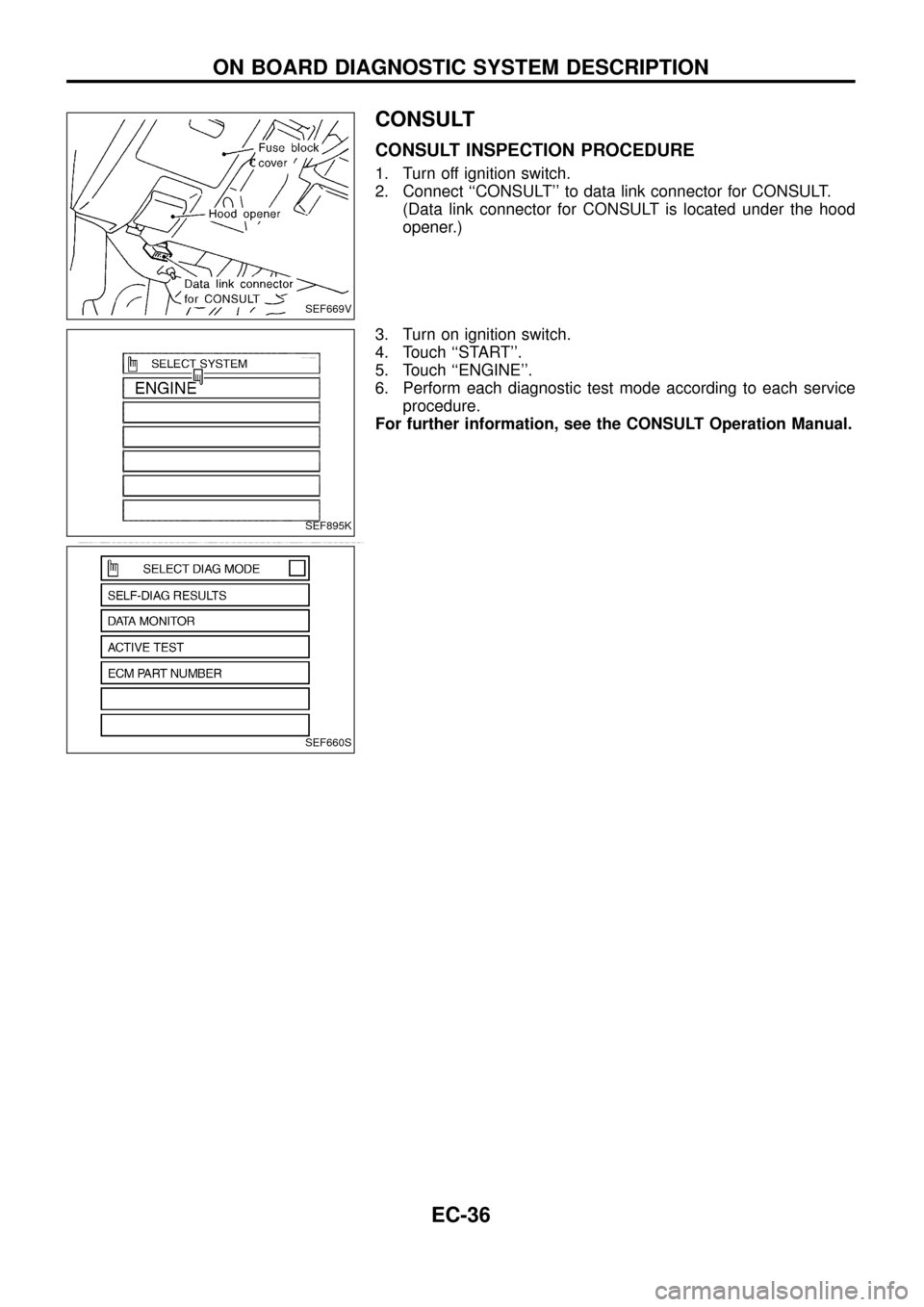
CONSULT INSPECTION PROCEDURE
1. Turn off ignition switch.
2. Connect ``CONSULT'' to data link connector for CONSULT.
(Data link connector for CONSULT is located under the hood
opener.)
3. Turn on ignition switch.
4. Touch ``START''.
5. Touch ``ENGINE''.
6. Perform each diagnostic test mode according to each service
procedure.
For further information, see the CONSULT Operation Manual.
SEF669V
SEF895K
SEF660S
ON BOARD DIAGNOSTIC SYSTEM DESCRIPTION
EC-36
Page 45 of 192
Diagnostic Worksheet
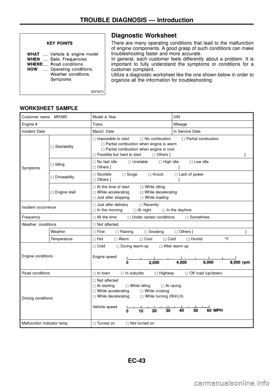
There are many operating conditions that lead to the malfunction
of engine components. A good grasp of such conditions can make
troubleshooting faster and more accurate.
In general, each customer feels differently about a problem. It is
important to fully understand the symptoms or conditions for a
customer complaint.
Utilize a diagnostic worksheet like the one shown below in order to
organize all the information for troubleshooting.
WORKSHEET SAMPLE
Customer name MR/MS Model & Year VIN
Engine # Trans. Mileage
Incident Date Manuf. Date In Service Date
SymptomshStartabilityhImpossible to starthNo combustionhPartial combustion
hPartial combustion when engine is warm
hPartial combustion when engine is cool
hPossible but hard to starthOthers [ ]
hIdlinghNo fast idlehUnstablehHigh idlehLow idle
hOthers [ ]
hDriveabilityhStumblehSurgehKnockhLack of power
hOthers [ ]
hEngine stallhAt the time of starthWhile idling
hWhile acceleratinghWhile decelerating
hJust after stoppinghWhile loading
Incident occurrencehJust after deliveryhRecently
hIn the morninghAt nighthIn the daytime
FrequencyhAll the timehUnder certain conditionshSometimes
Weather conditionshNot affected
WeatherhFinehRaininghSnowinghOthers [ ]
TemperaturehHothWarmhCoolhColdhHumid ÉF
Engine conditionshColdhDuring warm-uphAfter warm-up
Engine speed
Road conditionshIn townhIn suburbshHighwayhOff road (up/down)
Driving conditionshNot affected
hAt startinghWhile idlinghAt racing
hWhile acceleratinghWhile cruising
hWhile deceleratinghWhile turning (RH/LH)
Vehicle speed
Malfunction indicator lamphTurned onhNot turned on
SEF907L
TROUBLE DIAGNOSIS Ð Introduction
EC-43
Page 46 of 192

Work Flow
CHECK IN
CHECK INCIDENT CONDITIONS.
Listen to customer complaints. (Get symptoms.).................................................
STEP I
Check andPRINT OUT(write down) Diagnostic Trouble Code (DTC).
Then clear. Also check related service bulletins for information.
...........................................
STEP II
Symptoms
collected.No symptoms, except MIL
lights up, or Malfunction
Code exists at STEP II.
Verify the symptom by driving in the condition the cus-
tomer described.
.
*1
.............................................................................................
STEP III
Normal Code
(at STEP II)
Malfunction Code
(at STEP II)
INCIDENT CONFIRMATION
Verify the DTC by performing the ``DTC CONFIRMATION PROCEDURE''.
*1
...........................................
STEP IV
cChoose the appropriate action.
Malfunction Code (at STEP II or IV) Normal Code (at both STEP II and IV)...........................................
*2STEP V
BASIC INSPECTION
SYMPTOM BASIS (at STEP I or III)
................................................................
c
Perform inspections
according to Symptom
Matrix Chart.
.
TROUBLE DIAGNOSIS FOR DTC XX.STEP VI
REPAIR/REPLACE
NGFINAL CHECK
Con®rm that the incident is completely ®xed by performing BASIC INSPECTION and
DTC CONFIRMATION PROCEDURE (or OVERALL FUNCTION CHECK). Then,
erase the unnecessary (already ®xed) DTCs in ECM.
OK...........................................
STEP VII
CHECK OUT
*1: If the incident cannot be duplicated, refer to GI section (``Incident Simulation Tests'', ``HOW TO PERFORM EFFICIENT
DIAGNOSIS FOR AN ELECTRICAL INCIDENT'').
*2: If the on board diagnostic system cannot be performed, check main power supply and ground circuit. Refer to
``TROUBLE DIAGNOSIS FOR POWER SUPPLY'', EC-63.
.
.
.
.
.
.
.
.
.
.
.
TROUBLE DIAGNOSIS Ð Work Flow
EC-44
Page 48 of 192
Basic Inspection
Precaution:
Perform Basic Inspection without electrical or mechanical
loads applied;
+Headlamp switch is OFF,
+Air conditioner switch is OFF,
+Rear defogger switch is OFF,
+Steering wheel is in the straight-ahead position, etc.
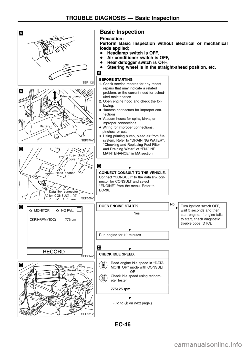
BEFORE STARTING
1. Check service records for any recent
repairs that may indicate a related
problem, or the current need for sched-
uled maintenance.
2. Open engine hood and check the fol-
lowing:
+Harness connectors for improper con-
nections
+Vacuum hoses for splits, kinks, or
improper connections
+Wiring for improper connections,
pinches, or cuts
3. Using priming pump, bleed air from fuel
system. Refer to ``DRAINING WATER'',
``Checking and Replacing Fuel Filter
and Draining Water'' of ``ENGINE
MAINTENANCE'' in MA section.
CONNECT CONSULT TO THE VEHICLE.
Connect ``CONSULT'' to the data link con-
nector for CONSULT and select
``ENGINE'' from the menu. Refer to
EC-36.
DOES ENGINE START?
Ye s
cNo
Turn ignition switch OFF,
wait 5 seconds and then
start engine. If engine fails
to start, check diagnostic
trouble code (DTC).
Run engine for 10 minutes.
CHECK IDLE SPEED.
----------------------------------------------------------------------------------------------------------------------------------------------------------------------------------------------------------------------------------------------------------------------------------------------------------------
Read engine idle speed in ``DATA
MONITOR'' mode with CONSULT.
--------------------------------------------------------------------------------------------------------------------------------------OR--------------------------------------------------------------------------------------------------------------------------------------
Check idle speed using tachom-
eter tester.
----------------------------------------------------------------------------------------------------------------------------------------------------------------------------------------------------------------------------------------------------------------------------------------------------------------
775 25 rpm
(Go tojAon next page.)
SEF142I
SEF670V
SEF669V
SEF714V
SEF671V
.
.
.
.
.
TROUBLE DIAGNOSIS Ð Basic Inspection
EC-46
Page 191 of 192
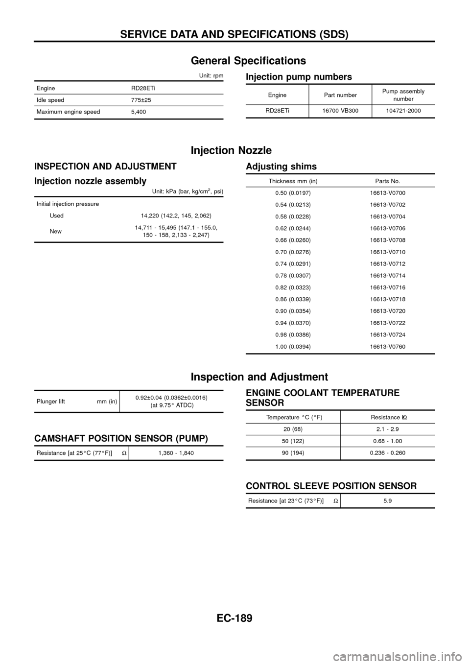
General Speci®cations
Unit: rpm
Engine RD28ETi
Idle speed 775 25
Maximum engine speed 5,400
Injection pump numbers
Engine Part numberPump assembly
number
RD28ETi 16700 VB300 104721-2000
Injection Nozzle
INSPECTION AND ADJUSTMENT
Injection nozzle assembly
Unit: kPa (bar, kg/cm2, psi)
Initial injection pressure
Used 14,220 (142.2, 145, 2,062)
New14,711 - 15,495 (147.1 - 155.0,
150 - 158, 2,133 - 2,247)
Adjusting shims
Thickness mm (in) Parts No.
0.50 (0.0197) 16613-V0700
0.54 (0.0213) 16613-V0702
0.58 (0.0228) 16613-V0704
0.62 (0.0244) 16613-V0706
0.66 (0.0260) 16613-V0708
0.70 (0.0276) 16613-V0710
0.74 (0.0291) 16613-V0712
0.78 (0.0307) 16613-V0714
0.82 (0.0323) 16613-V0716
0.86 (0.0339) 16613-V0718
0.90 (0.0354) 16613-V0720
0.94 (0.0370) 16613-V0722
0.98 (0.0386) 16613-V0724
1.00 (0.0394) 16613-V0760
Inspection and Adjustment
Plunger lift mm (in)0.92 0.04 (0.0362 0.0016)
(at 9.75É ATDC)
CAMSHAFT POSITION SENSOR (PUMP)
Resistance [at 25ÉC (77ÉF)]W1,360 - 1,840
ENGINE COOLANT TEMPERATURE
SENSOR
Temperature ÉC (ÉF) Resistance kW
20 (68) 2.1 - 2.9
50 (122) 0.68 - 1.00
90 (194) 0.236 - 0.260
CONTROL SLEEVE POSITION SENSOR
Resistance [at 23ÉC (73ÉF)]W5.9
SERVICE DATA AND SPECIFICATIONS (SDS)
EC-189