dimensions NISSAN PATROL 1998 Y61 / 5.G Engine Mechanical Workshop Manual
[x] Cancel search | Manufacturer: NISSAN, Model Year: 1998, Model line: PATROL, Model: NISSAN PATROL 1998 Y61 / 5.GPages: 65, PDF Size: 2.4 MB
Page 6 of 65

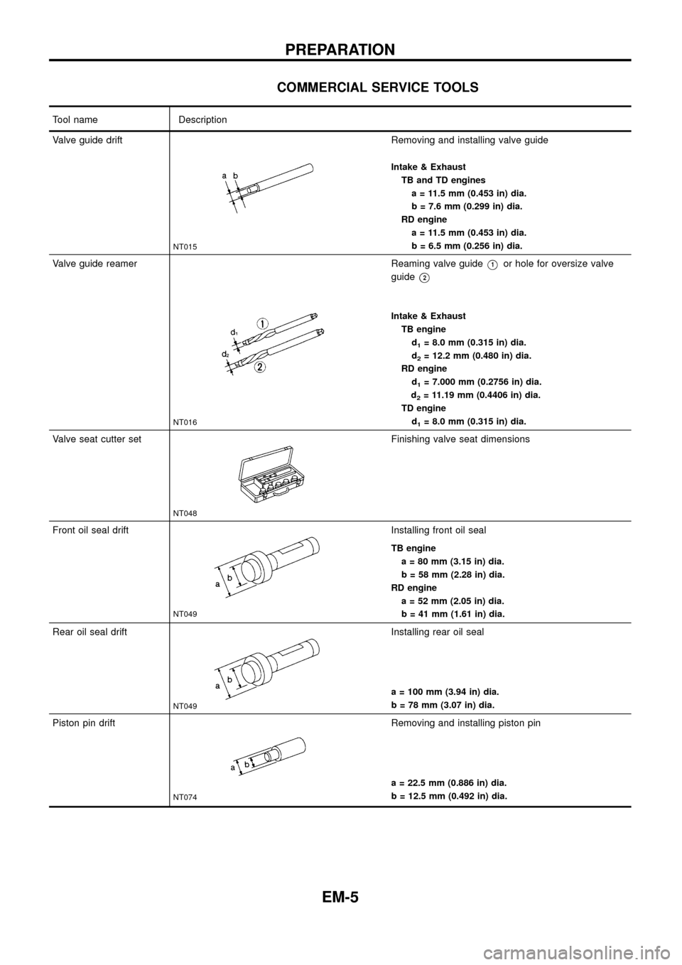
COMMERCIAL SERVICE TOOLS
Tool name Description
Valve guide drift
NT015
Removing and installing valve guide
Intake & Exhaust
TB and TD engines
a = 11.5 mm (0.453 in) dia.
b = 7.6 mm (0.299 in) dia.
RD engine
a = 11.5 mm (0.453 in) dia.
b = 6.5 mm (0.256 in) dia.
Valve guide reamer
NT016
Reaming valve guideV1or hole for oversize valve
guide
V2
Intake & Exhaust
TB engine
d
1= 8.0 mm (0.315 in) dia.
d
2= 12.2 mm (0.480 in) dia.
RD engine
d
1= 7.000 mm (0.2756 in) dia.
d
2= 11.19 mm (0.4406 in) dia.
TD engine
d
1= 8.0 mm (0.315 in) dia.
Valve seat cutter set
NT048
Finishing valve seat dimensions
Front oil seal drift
NT049
Installing front oil seal
TB engine
a = 80 mm (3.15 in) dia.
b = 58 mm (2.28 in) dia.
RD engine
a = 52 mm (2.05 in) dia.
b = 41 mm (1.61 in) dia.
Rear oil seal drift
NT049
Installing rear oil seal
a = 100 mm (3.94 in) dia.
b = 78 mm (3.07 in) dia.
Piston pin drift
NT074
Removing and installing piston pin
a = 22.5 mm (0.886 in) dia.
b = 12.5 mm (0.492 in) dia.
PREPARATION
EM-5
Page 35 of 65

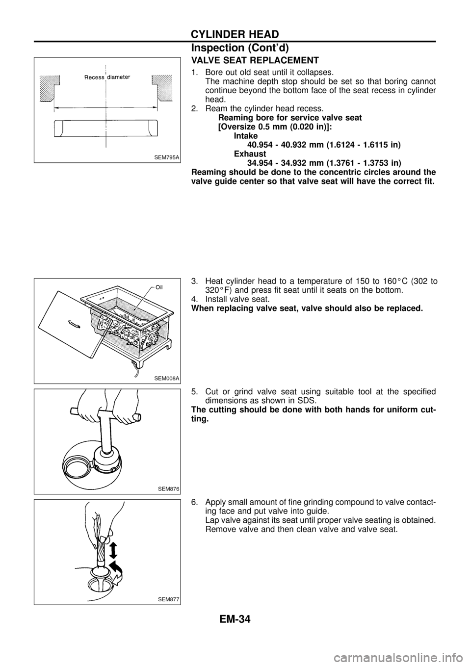
VALVE SEAT REPLACEMENT
1. Bore out old seat until it collapses.
The machine depth stop should be set so that boring cannot
continue beyond the bottom face of the seat recess in cylinder
head.
2. Ream the cylinder head recess.
Reaming bore for service valve seat
[Oversize 0.5 mm (0.020 in)]:
Intake
40.954 - 40.932 mm (1.6124 - 1.6115 in)
Exhaust
34.954 - 34.932 mm (1.3761 - 1.3753 in)
Reaming should be done to the concentric circles around the
valve guide center so that valve seat will have the correct ®t.
3. Heat cylinder head to a temperature of 150 to 160ÉC (302 to
320ÉF) and press ®t seat until it seats on the bottom.
4. Install valve seat.
When replacing valve seat, valve should also be replaced.
5. Cut or grind valve seat using suitable tool at the speci®ed
dimensions as shown in SDS.
The cutting should be done with both hands for uniform cut-
ting.
6. Apply small amount of ®ne grinding compound to valve contact-
ing face and put valve into guide.
Lap valve against its seat until proper valve seating is obtained.
Remove valve and then clean valve and valve seat.
SEM795A
SEM008A
SEM876
SEM877
CYLINDER HEAD
Inspection (Cont'd)
EM-34
Page 36 of 65

7. Measure distance from cylinder head surface to intake and
exhaust valves. If speci®ed distance is exceeded, replace
valve(s) or valve seat(s).
Speci®ed distance: mm (in)
Standard
þ0.069 to 0.269 (þ0.0027 to 0.0106)
VALVE DIMENSIONS
1. Check dimensions in each valve. For dimensions, refer to SDS.
2. Correct or replace any valve that is out of tolerance.
3. Valve face or valve stem end surface should be refaced by
using a valve grinder.
When valve head has been worn down to 0.5 mm (0.020 in) in
margin thickness, replace the valve.
Grinding allowance for valve stem tip is 0.2 mm (0.008 in) or
less.
VALVE SPRING SQUARENESS
Check valve spring for squareness using a steel square and sur-
face plate.
If spring is out-of-square ``S'' more than speci®ed limit, replace with
new one.
Out-of-square:
Outer
Less than 1.9 mm (0.075 in)
Inner
Less than 1.6 mm (0.063 in)
VALVE SPRING PRESSURE LOAD
Measure the free length and the tension of each spring. If the
measured value exceeds the speci®ed limit, replace spring. Refer
to SDS.
SEM787F
EM030
E M 111
SEM333
EM113
CYLINDER HEAD
Inspection (Cont'd)
EM-35