oil pressure NISSAN PATROL 1998 Y61 / 5.G Engine Mechanical Workshop Manual
[x] Cancel search | Manufacturer: NISSAN, Model Year: 1998, Model line: PATROL, Model: NISSAN PATROL 1998 Y61 / 5.GPages: 65, PDF Size: 2.4 MB
Page 1 of 65

ENGINE MECHANICAL
SECTION
EM
CONTENTS
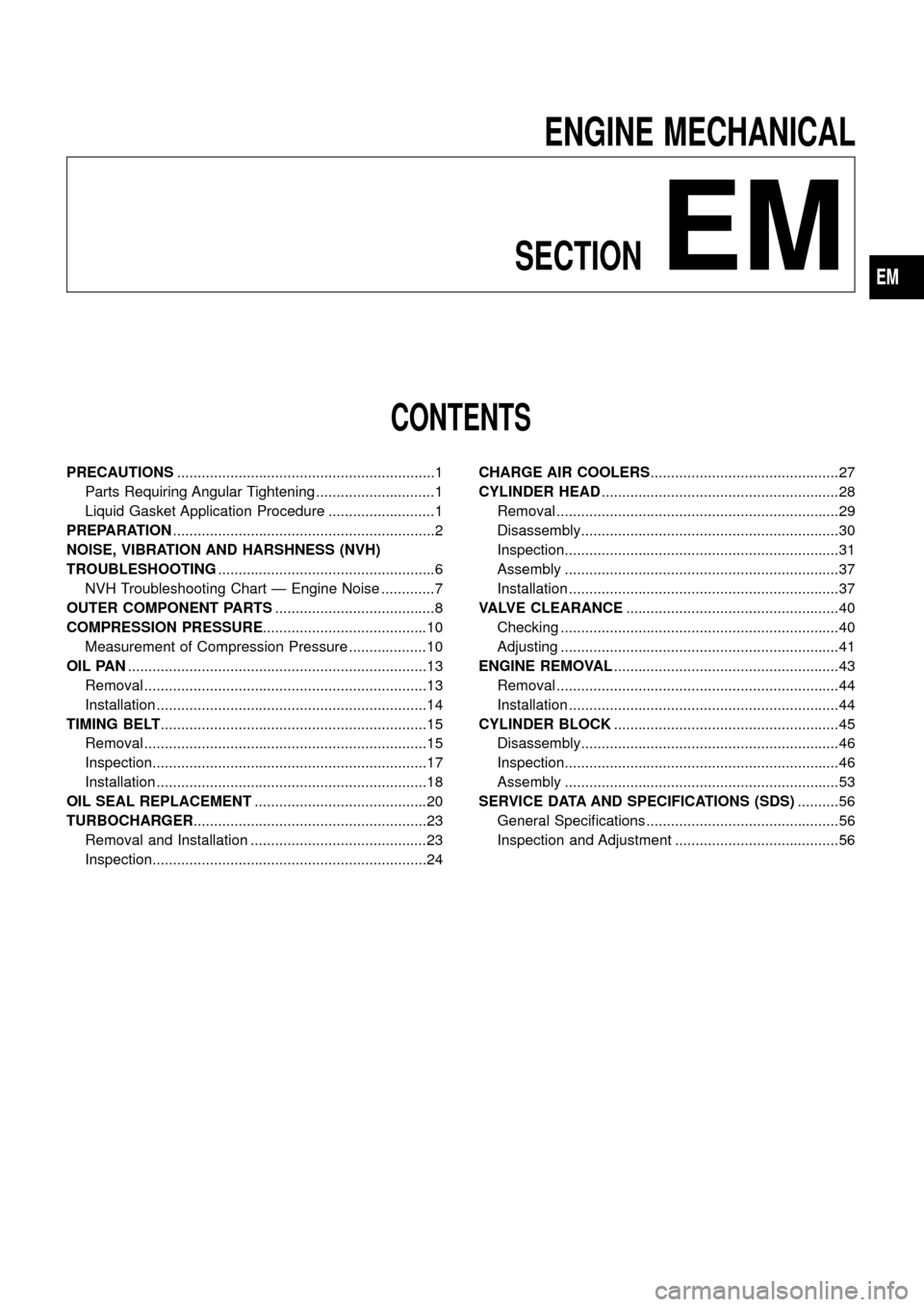
PRECAUTIONS...............................................................1
Parts Requiring Angular Tightening .............................1
Liquid Gasket Application Procedure ..........................1
PREPARATION................................................................2
NOISE, VIBRATION AND HARSHNESS (NVH)
TROUBLESHOOTING.....................................................6
NVH Troubleshooting Chart Ð Engine Noise .............7
OUTER COMPONENT PARTS.......................................8
COMPRESSION PRESSURE........................................10
Measurement of Compression Pressure ...................10
OIL PAN.........................................................................13
Removal .....................................................................13
Installation ..................................................................14
TIMING BELT.................................................................15
Removal .....................................................................15
Inspection...................................................................17
Installation ..................................................................18
OIL SEAL REPLACEMENT..........................................20
TURBOCHARGER.........................................................23
Removal and Installation ...........................................23
Inspection...................................................................24CHARGE AIR COOLERS..............................................27
CYLINDER HEAD..........................................................28
Removal .....................................................................29
Disassembly...............................................................30
Inspection...................................................................31
Assembly ...................................................................37
Installation ..................................................................37
VALVE CLEARANCE....................................................40
Checking ....................................................................40
Adjusting ....................................................................41
ENGINE REMOVAL.......................................................43
Removal .....................................................................44
Installation ..................................................................44
CYLINDER BLOCK.......................................................45
Disassembly...............................................................46
Inspection...................................................................46
Assembly ...................................................................53
SERVICE DATA AND SPECIFICATIONS (SDS)..........56
General Speci®cations ...............................................56
Inspection and Adjustment ........................................56
EM
Page 13 of 65

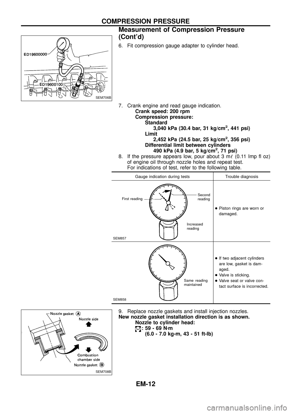
6. Fit compression gauge adapter to cylinder head.
7. Crank engine and read gauge indication.
Crank speed: 200 rpm
Compression pressure:
Standard
3,040 kPa (30.4 bar, 31 kg/cm
2, 441 psi)
Limit
2,452 kPa (24.5 bar, 25 kg/cm
2, 356 psi)
Differential limit between cylinders
490 kPa (4.9 bar, 5 kg/cm
2, 71 psi)
8. If the pressure appears low, pour about 3 m!(0.11 Imp ¯ oz)
of engine oil through nozzle holes and repeat test.
For indications of test, refer to the following table.
Gauge indication during tests Trouble diagnosis
SEM857
+Piston rings are worn or
damaged.
SEM858
+If two adjacent cylinders
are low, gasket is dam-
aged.
+Valve is sticking.
+Valve seat or valve con-
tact surface is incorrected.
9. Replace nozzle gaskets and install injection nozzles.
New nozzle gasket installation direction is as shown.
Nozzle to cylinder head:
:59-69Nzm
(6.0 - 7.0 kg-m, 43 - 51 ft-lb)
SEM706B
SEM708B
COMPRESSION PRESSURE
Measurement of Compression Pressure
(Cont'd)
EM-12
First readingSecond
reading
Increased
reading
Same reading
maintained
Page 58 of 65

General Speci®cations
Cylinder arrangement In-line 6
Displacement cm
3(cu in) 2,826 (172.44)
Bore and stroke mm (in) 85 x 83 (3.35 x 3.27)
Valve arrangement OHC
Firing order 1-5-3-6-2-4
Number of piston rings
Compression 2
Oil 1
Number of main bearings 7
Compression ratio 21.8
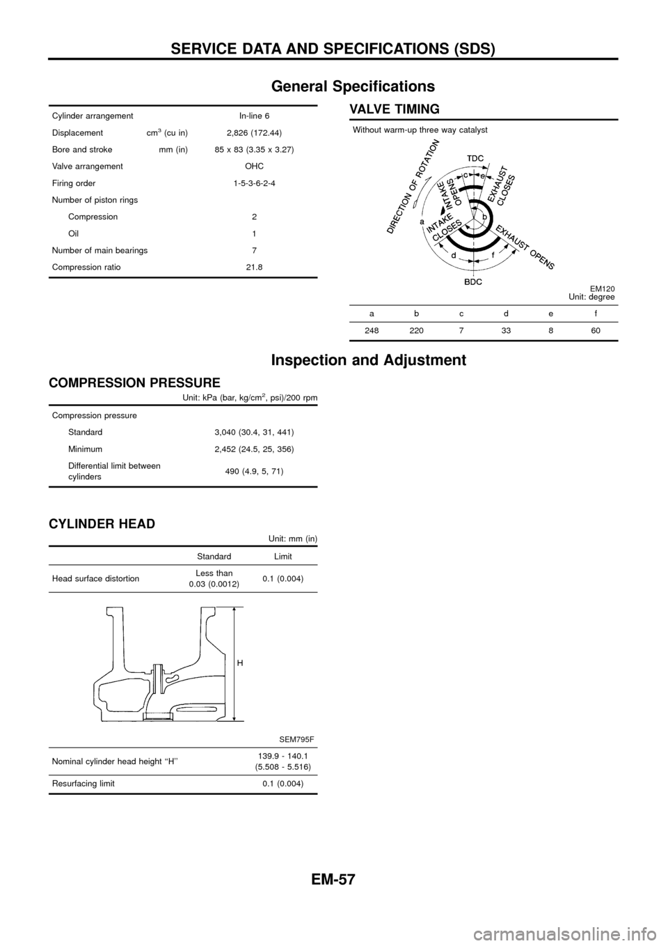
VALVE TIMING
Without warm-up three way catalyst
EM120Unit: degree
abcde f
248 220 7 33 8 60
Inspection and Adjustment
COMPRESSION PRESSURE
Unit: kPa (bar, kg/cm2, psi)/200 rpm
Compression pressure
Standard 3,040 (30.4, 31, 441)
Minimum 2,452 (24.5, 25, 356)
Differential limit between
cylinders490 (4.9, 5, 71)
CYLINDER HEAD
Unit: mm (in)
Standard Limit
Head surface distortionLess than
0.03 (0.0012)0.1 (0.004)
SEM795F
Nominal cylinder head height ``H''139.9 - 140.1
(5.508 - 5.516)
Resurfacing limit 0.1 (0.004)
SERVICE DATA AND SPECIFICATIONS (SDS)
EM-57