NISSAN PATROL 1998 Y61 / 5.G Heather And Air Conditioner User Guide
PATROL 1998 Y61 / 5.G
NISSAN
NISSAN
https://www.carmanualsonline.info/img/5/622/w960_622-0.png
NISSAN PATROL 1998 Y61 / 5.G Heather And Air Conditioner User Guide
Page 51 of 128

Introduction
AIR CONDITIONER LAN SYSTEM OVERVIEW CONTROL SYSTEM
The LAN system consists of auto amp., air mix door motor and mode door motor.
A con®guration of these components is shown in the diagram below.
Features
SYSTEM CONSTRUCTION (LAN)
A small network is constructed between the auto ampli®er, air mix door motor and mode door motor. The auto
ampli®er and motors are connected by data transmission lines and motor power supply lines. The LAN net-
work is built through the ground circuits of the two motors.
Addresses, motor opening angle signals, motor stop signals and error checking messages are all transmitted
through the data transmission lines connecting the auto ampli®er and two motors.
The following functions are contained in LCUs built into the air mix door motor and the mode door motor.
+Address
+Motor opening angle signals
+Data transmission
+Motor stop and drive decision
+Opening angle sensor (PBR function)
+Comparison
+Decision (Auto ampli®er indicated value and motor opening angle comparison)
RHA439G
RHA440GA
DESCRIPTIONAUTO
HA-49
Page 54 of 128
Overview of Control System
The control system consists of input sensors, switches, the automatic ampli®er (microcomputer) and outputs.
The relationship of these components is shown in the diagram below:
RHA732G
DESCRIPTIONAUTO
HA-52
Page 59 of 128
Circuit Diagram
THA153
TROUBLE DIAGNOSESAUTO
HA-57
Page 60 of 128
Wiring Diagram Ð A/C, A Ð
YHA159
TROUBLE DIAGNOSESAUTO
HA-58
Page 61 of 128
YHA160
TROUBLE DIAGNOSESAUTO
Wiring Diagram Ð A/C, A Ð (Cont'd)
HA-59
Page 62 of 128
YHA161
TROUBLE DIAGNOSESAUTO
Wiring Diagram Ð A/C, A Ð (Cont'd)
HA-60
Page 92 of 128

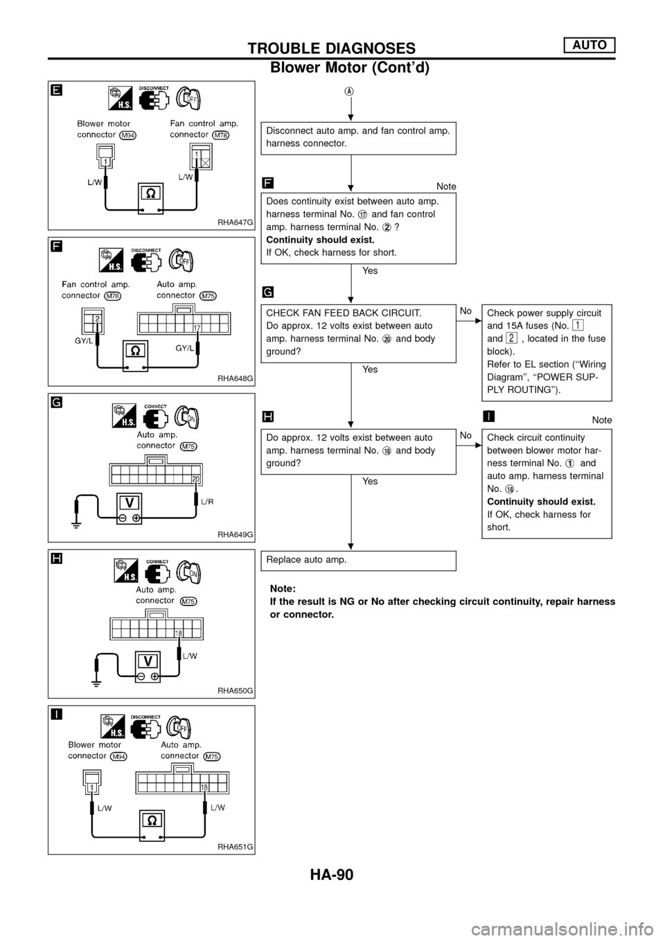
jA
Disconnect auto amp. and fan control amp.
harness connector.
Note
Does continuity exist between auto amp.
harness terminal No.j
17and fan control
amp. harness terminal No.j
2?
Continuity should exist.
If OK, check harness for short.
Ye s
CHECK FAN FEED BACK CIRCUIT.
Do approx. 12 volts exist between auto
amp. harness terminal No.j
20and body
ground?
Ye s
cNo
Check power supply circuit
and 15A fuses (No.
1
and2, located in the fuse
block).
Refer to EL section (``Wiring
Diagram'', ``POWER SUP-
PLY ROUTING'').
Note
Do approx. 12 volts exist between auto
amp. harness terminal No.j
18and body
ground?
Ye s
cNo
Check circuit continuity
between blower motor har-
ness terminal No.j
1and
auto amp. harness terminal
No.j
18.
Continuity should exist.
If OK, check harness for
short.
Replace auto amp.
Note:
If the result is NG or No after checking circuit continuity, repair harness
or connector.
RHA647G
RHA648G
RHA649G
RHA650G
RHA651G
.
.
.
.
.
TROUBLE DIAGNOSESAUTO
Blower Motor (Cont'd)
HA-90
Page 96 of 128

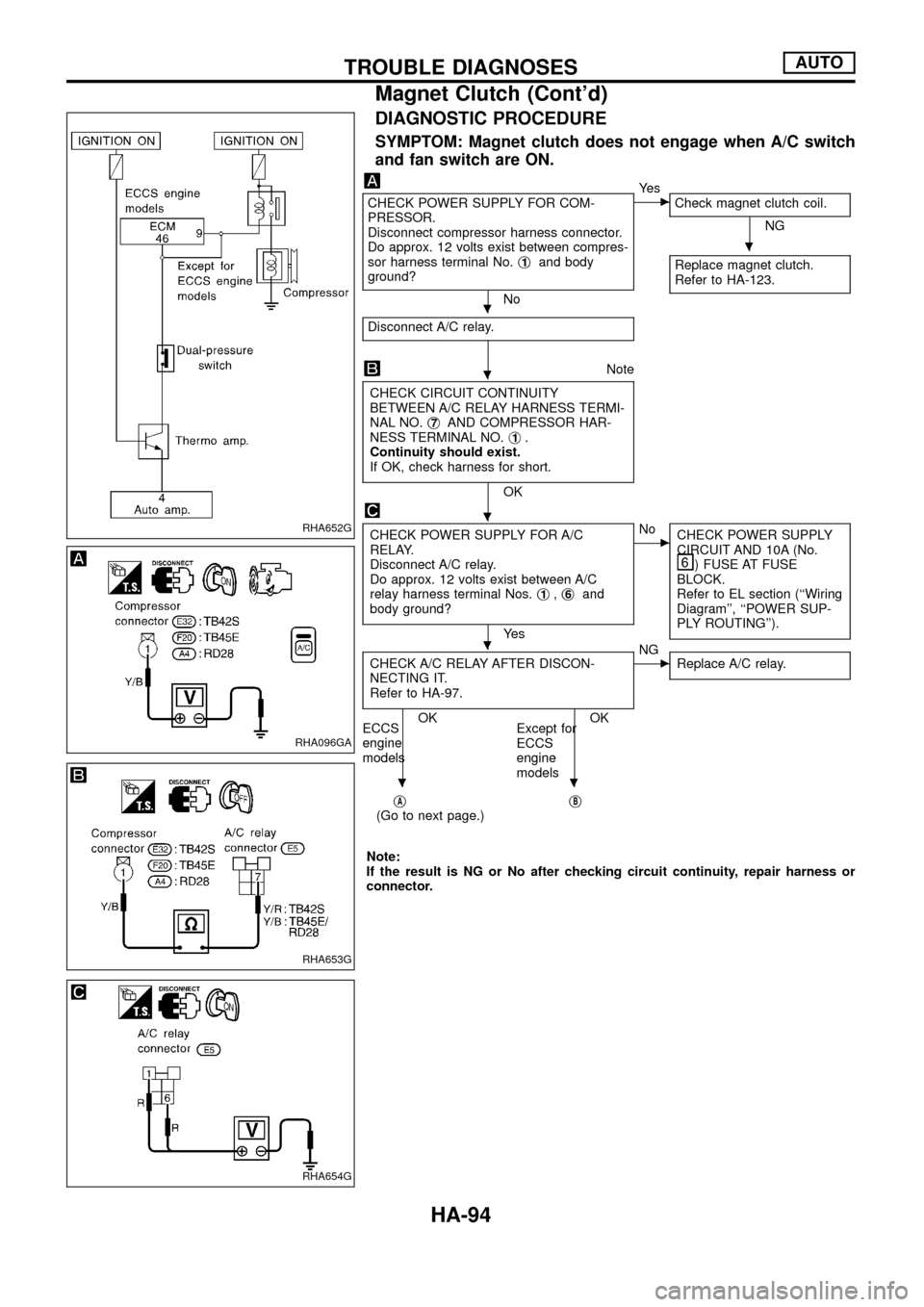
DIAGNOSTIC PROCEDURE
SYMPTOM: Magnet clutch does not engage when A/C switch
and fan switch are ON.
CHECK POWER SUPPLY FOR COM-
PRESSOR.
Disconnect compressor harness connector.
Do approx. 12 volts exist between compres-
sor harness terminal No.j
1and body
ground?
No
cYe s
Check magnet clutch coil.
NG
Replace magnet clutch.
Refer to HA-123.
Disconnect A/C relay.
Note
CHECK CIRCUIT CONTINUITY
BETWEEN A/C RELAY HARNESS TERMI-
NAL NO.j
7AND COMPRESSOR HAR-
NESS TERMINAL NO.j1.
Continuity should exist.
If OK, check harness for short.
OK
CHECK POWER SUPPLY FOR A/C
RELAY.
Disconnect A/C relay.
Do approx. 12 volts exist between A/C
relay harness terminal Nos.j
1,j6and
body ground?
Ye s
cNo
CHECK POWER SUPPLY
CIRCUIT AND 10A (No.
) FUSE AT FUSE
BLOCK.
Refer to EL section (``Wiring
Diagram'', ``POWER SUP-
PLY ROUTING'').
CHECK A/C RELAY AFTER DISCON-
NECTING IT.
Refer to HA-97.
OK OK
ECCS
engine
modelsExcept for
ECCS
engine
models
cNG
Replace A/C relay.
jA(Go to next page.)jB
Note:
If the result is NG or No after checking circuit continuity, repair harness or
connector.
RHA652G
RHA096GA
RHA653G
RHA654G
.
.
.
.
.
..
TROUBLE DIAGNOSESAUTO
Magnet Clutch (Cont'd)
HA-94


