light NISSAN PATROL 1998 Y61 / 5.G Heather And Air Conditioner Workshop Manual
[x] Cancel search | Manufacturer: NISSAN, Model Year: 1998, Model line: PATROL, Model: NISSAN PATROL 1998 Y61 / 5.GPages: 128, PDF Size: 3.77 MB
Page 9 of 128

HFC-134a (R-134a) Service Tools and
Equipment
Never mix HFC-134a refrigerant and/or its speci®ed lubricant with CFC-12 (R-12) refrigerant and/or its lubri-
cant.
Separate and non-interchangeable service equipment must be used for each type of refrigerant/lubricant.
Refrigerant container ®ttings, service hose ®ttings and service equipment ®ttings (equipment which handles
refrigerant and/or lubricant) are different between CFC-12 (R-12) and HFC-134a (R-134a). This is to avoid
mixed use of the refrigerants/lubricant.
Adapters that convert one size ®tting to another must never be used: refrigerant/lubricant contamination will
occur and compressor failure will result.
Tool name Description Note
HFC-134a (R-134a) refrig-
erant
NT196
Container color: Light blue
Container marking: HFC-134a (R-134a)
Fitting size: Thread size
+large container 1/2²-16 ACME
Nissan A/C System Oil
Type S
NT197
Type: Poly alkylene glycol oil (PAG), type S
Application: HFC-134a (R-134a) swash plate
(piston) compressors (Nissan only)
Lubricity: 40 m!(1.4 Imp ¯ oz)
Recovery/Recycling/
Recharging equipment
NT195
Function: Refrigerant Recovery and Recycling
and Recharging
Electrical leak detector
NT198
Power supply:
+DC 12V (Cigarette lighter)
Manifold gauge set (with
hoses and couplers)
NT199
Identi®cation:
+The gauge face indicates R-134a.
Fitting size: Thread size
+1/2²-16 ACME
PRECAUTIONS AND PREPARATIONMANUAL AND AUTO
HA-7
Page 18 of 128

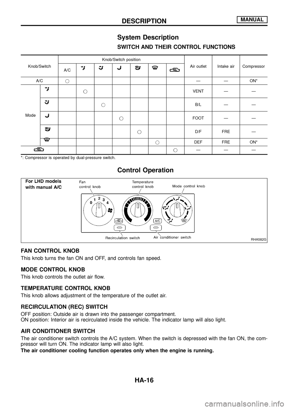
System Description
SWITCH AND THEIR CONTROL FUNCTIONS
Knob/SwitchKnob/Switch position
Air outlet Intake air Compressor
A/C
A/CjÐ Ð ON*
Mode
jVENT Ð Ð
jB/L Ð Ð
jFOOT Ð Ð
jD/F FRE Ð
jDEF FRE ON*
jÐÐÐ
*: Compressor is operated by dual-pressure switch.
Control Operation
FAN CONTROL KNOB
This knob turns the fan ON and OFF, and controls fan speed.
MODE CONTROL KNOB
This knob controls the outlet air ¯ow.
TEMPERATURE CONTROL KNOB
This knob allows adjustment of the temperature of the outlet air.
RECIRCULATION (REC) SWITCH
OFF position: Outside air is drawn into the passenger compartment.
ON position: Interior air is recirculated inside the vehicle. The indicator lamp will also light.
AIR CONDITIONER SWITCH
The air conditioner switch controls the A/C system. When the switch is depressed with the fan ON, the com-
pressor will turn ON. The indicator lamp will also light.
The air conditioner cooling function operates only when the engine is running.
RHA582G
DESCRIPTIONMANUAL
HA-16
Page 25 of 128

3. Check recirculation
a. Press recirculation switch.
Recirculation indicator should light.
b. Listen for intake door position change (you should hear blower
sound change slightly).
4. Check temperature decrease
a. Turn temperature control knob to full cold.
b. Check for cold air at discharge air outlets.
5. Check temperature increase
a. Turn temperature control knob to full hot.
b. Check for hot air at discharge air outlets.
6. Check air conditioner switch
Turn fan control knob to the desired (1 to 4-speed) position and
push the air conditioner switch to turn ON the air conditioner.
The indicator light should come on when air conditioner is ON.
RHA585G
RHA586G
RHA587G
RHA588G
TROUBLE DIAGNOSESMANUAL
Operational Check (Cont'd)
HA-23
Page 67 of 128

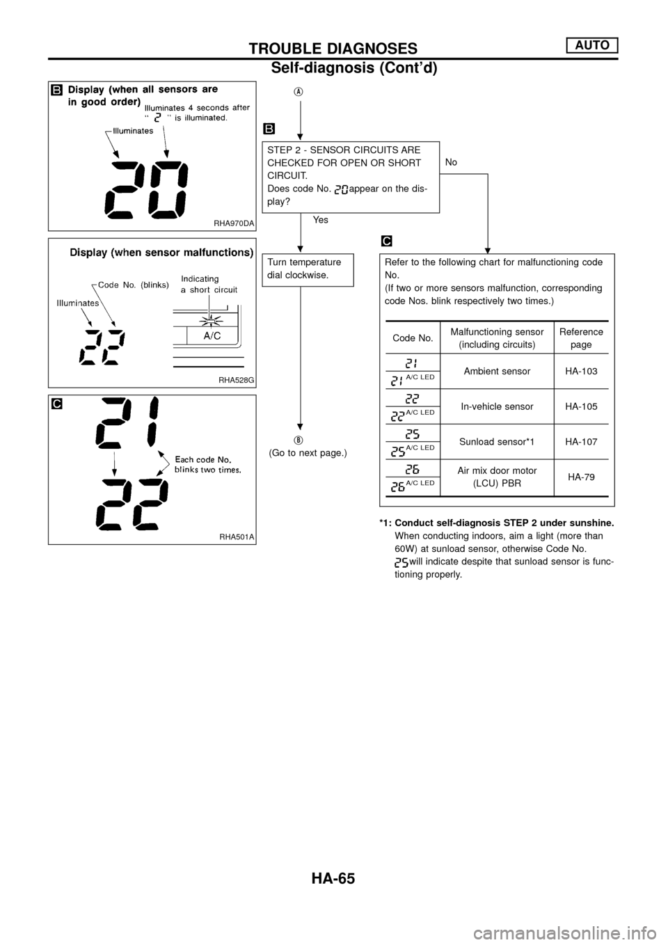
jA
STEP 2 - SENSOR CIRCUITS ARE
CHECKED FOR OPEN OR SHORT
CIRCUIT.
Does code No.
appear on the dis-
play?
Ye sNo
.
Turn temperature
dial clockwise.Refer to the following chart for malfunctioning code
No.
(If two or more sensors malfunction, corresponding
code Nos. blink respectively two times.)
*1: Conduct self-diagnosis STEP 2 under sunshine.
When conducting indoors, aim a light (more than
60W) at sunload sensor, otherwise Code No.
will indicate despite that sunload sensor is func-
tioning properly. j
B
(Go to next page.)
Code No.Malfunctioning sensor
(including circuits)Reference
page
Ambient sensor HA-103A/C LED
In-vehicle sensor HA-105A/C LED
Sunload sensor*1 HA-107A/C LED
Air mix door motor
(LCU) PBRHA-79
A/C LED
RHA970DA
RHA528G
RHA501A
.
.
.
TROUBLE DIAGNOSESAUTO
Self-diagnosis (Cont'd)
HA-65
Page 73 of 128

b. Con®rm that discharge air comes out according to the air dis-
tribution table at left.
Refer to ``Discharge Air Flow'' (HA-13).
NOTE:
Con®rm that the compressor clutch is engaged (visualinspec-
tion) and intake door position is at FRESH when the DEF
is selected.
Intake door position is checked in the next step.
4. Check recirculation
a. Press RECswitch.
Recirculation indicator should illuminate.
b. Listen for intake door position change (you should hear blower
sound change slightly).
5. Check temperature dial
a. Turn temperature dial counterclockwise until 18ÉC is displayed.
b. Check for cold air at discharge air outlets.
c. Turn temperature dial clockwise until 32ÉC is displayed.
d. Check for hot air at discharge air outlets.
RHA654FD
RHA521G
RHA522G
TROUBLE DIAGNOSESAUTO
Operational Check (Cont'd)
HA-71
Page 74 of 128

6. Check AUTO mode
a. Press AUTO switch.
b. Display should indicate AUTO.
Con®rm that the compressor clutch engages (audio or visual
inspection).
(Discharge air and blower speed will depend on ambient,
in-vehicle, and set temperatures.)
7. Check FRESH switch
a. Press FRE switch.
FRESH indicator should illuminate.
b. Listen for intake door position change. (You should hear a slight
change in blower sound.)
8. Check A/C switch
a. Press A/C switch.
A/C indicator should illuminate.
b. Con®rm that the compressor clutch is engaged.
RHA523G
RHA524G
RHA525G
TROUBLE DIAGNOSESAUTO
Operational Check (Cont'd)
HA-72
Page 109 of 128

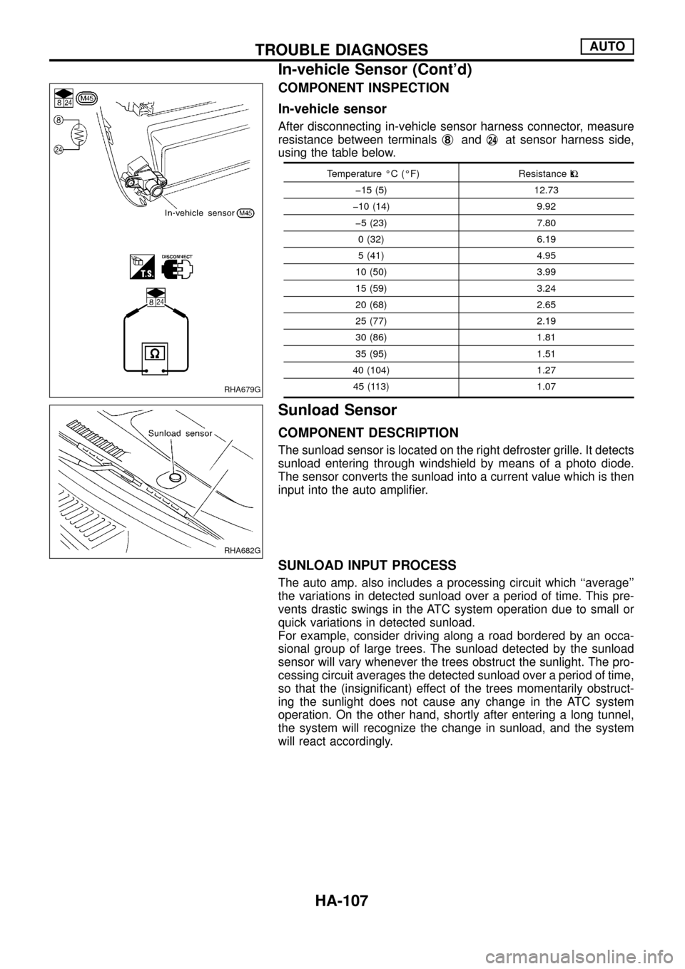
COMPONENT INSPECTION
In-vehicle sensor
After disconnecting in-vehicle sensor harness connector, measure
resistance between terminalsj
8andj24at sensor harness side,
using the table below.
Temperature ÉC (ÉF) Resistance kW
þ15 (5) 12.73
þ10 (14) 9.92
þ5 (23) 7.80
0 (32) 6.19
5 (41) 4.95
10 (50) 3.99
15 (59) 3.24
20 (68) 2.65
25 (77) 2.19
30 (86) 1.81
35 (95) 1.51
40 (104) 1.27
45 (113) 1.07
Sunload Sensor
COMPONENT DESCRIPTION
The sunload sensor is located on the right defroster grille. It detects
sunload entering through windshield by means of a photo diode.
The sensor converts the sunload into a current value which is then
input into the auto ampli®er.
SUNLOAD INPUT PROCESS
The auto amp. also includes a processing circuit which ``average''
the variations in detected sunload over a period of time. This pre-
vents drastic swings in the ATC system operation due to small or
quick variations in detected sunload.
For example, consider driving along a road bordered by an occa-
sional group of large trees. The sunload detected by the sunload
sensor will vary whenever the trees obstruct the sunlight. The pro-
cessing circuit averages the detected sunload over a period of time,
so that the (insigni®cant) effect of the trees momentarily obstruct-
ing the sunlight does not cause any change in the ATC system
operation. On the other hand, shortly after entering a long tunnel,
the system will recognize the change in sunload, and the system
will react accordingly.
RHA679G
RHA682G
TROUBLE DIAGNOSESAUTO
In-vehicle Sensor (Cont'd)
HA-107