differential NISSAN PATROL 1998 Y61 / 5.G Propeller Shaft And Differential Carrier Workshop Manual
[x] Cancel search | Manufacturer: NISSAN, Model Year: 1998, Model line: PATROL, Model: NISSAN PATROL 1998 Y61 / 5.GPages: 54, PDF Size: 1.85 MB
Page 1 of 54
PROPELLER SHAFT &
DIFFERENTIAL CARRIER
SECTION
PD
CONTENTS
PREPARATION................................................................1
Special Service Tools ..................................................1
NOISE, VIBRATION AND HARSHNESS (NVH)
TROUBLESHOOTING.....................................................4
NVH Troubleshooting Chart.........................................4
PROPELLER SHAFT......................................................5
Front Propeller Shaft ...................................................5
Rear Propeller Shaft ....................................................5
On-vehicle Service.......................................................6
Removal and Installation .............................................7
Inspection.....................................................................7
Disassembly.................................................................7
Assembly .....................................................................8
ON-VEHICLE SERVICE (Final Drive)..........................10
Front Oil Seal Replacement ......................................10
REMOVAL AND INSTALLATION.................................. 11
Removal ..................................................................... 11
Installation .................................................................. 11
FRONT FINAL DRIVE...................................................12
REAR FINAL DRIVE.....................................................13
DISASSEMBLY..............................................................14
Pre-inspection ............................................................14
Differential Carrier......................................................15
Differential Case ........................................................17
INSPECTION..................................................................19
Ring Gear and Drive Pinion ......................................19
Differential Case Assembly........................................19Bearing.......................................................................19
LIMITED SLIP DIFFERENTIAL.....................................20
Preparation for Disassembly .....................................20
Disassembly...............................................................21
Inspection...................................................................21
Adjustment .................................................................23
Assembly ...................................................................24
ADJUSTMENT...............................................................27
Drive Pinion Height ....................................................27
Tooth Contact.............................................................29
ASSEMBLY....................................................................31
Differential Case Ð 4-pinion type Ð.........................31
Differential Case Ð 2-pinion type Ð.........................32
Differential Carrier......................................................33
DIFFERENTIAL LOCK..................................................37
Actuator and Fork ......................................................37
Disassembly...............................................................38
Inspection...................................................................39
Assembly ...................................................................40
System Description ....................................................43
Component Parts Location ........................................44
Wiring Diagram Ð DIFF/L Ð/LHD Models ...............45
Wiring Diagram Ð DIFF/L Ð/RHD Models ...............47
Electrical Components Inspection .............................49
SERVICE DATA AND SPECIFICATIONS (SDS)..........51
Propeller Shaft ...........................................................51
Final Drive..................................................................52
PD
Page 2 of 54
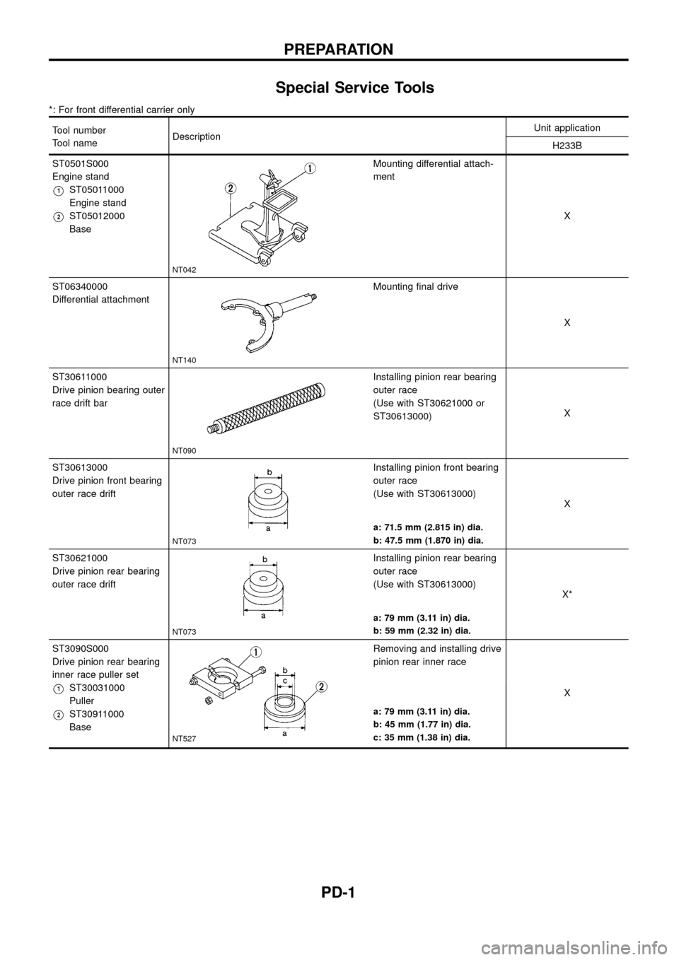
Special Service Tools
*: For front differential carrier only
Tool number
Tool nameDescriptionUnit application
H233B
ST0501S000
Engine stand
V1ST05011000
Engine stand
V2ST05012000
Base
NT042
Mounting differential attach-
ment
X
ST06340000
Differential attachment
NT140
Mounting ®nal drive
X
ST30611000
Drive pinion bearing outer
race drift bar
NT090
Installing pinion rear bearing
outer race
(Use with ST30621000 or
ST30613000)X
ST30613000
Drive pinion front bearing
outer race drift
NT073
Installing pinion front bearing
outer race
(Use with ST30613000)
X
a: 71.5 mm (2.815 in) dia.
b: 47.5 mm (1.870 in) dia.
ST30621000
Drive pinion rear bearing
outer race drift
NT073
Installing pinion rear bearing
outer race
(Use with ST30613000)
X*
a: 79 mm (3.11 in) dia.
b: 59 mm (2.32 in) dia.
ST3090S000
Drive pinion rear bearing
inner race puller set
V1ST30031000
Puller
V2ST30911000
Base
NT527
Removing and installing drive
pinion rear inner race
X
a: 79 mm (3.11 in) dia.
b: 45 mm (1.77 in) dia.
c: 35 mm (1.38 in) dia.
PREPARATION
PD-1
Page 3 of 54
Tool number
Tool nameDescriptionUnit application
H233B
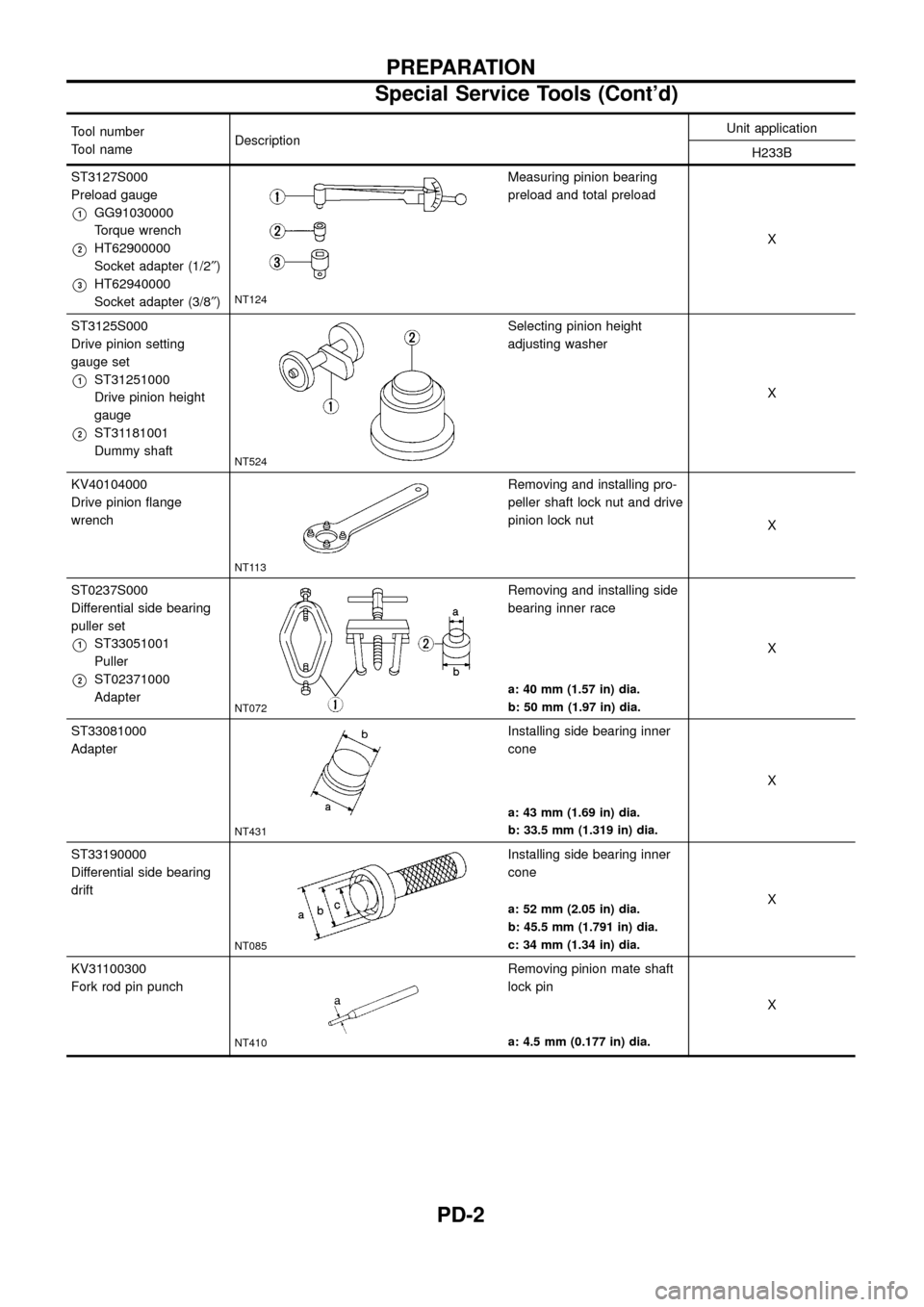
ST3127S000
Preload gauge
V1GG91030000
Torque wrench
V2HT62900000
Socket adapter (1/2²)
V3HT62940000
Socket adapter (3/8²)NT124
Measuring pinion bearing
preload and total preload
X
ST3125S000
Drive pinion setting
gauge set
V1ST31251000
Drive pinion height
gauge
V2ST31181001
Dummy shaft
NT524
Selecting pinion height
adjusting washer
X
KV40104000
Drive pinion ¯ange
wrench
NT113
Removing and installing pro-
peller shaft lock nut and drive
pinion lock nut
X
ST0237S000
Differential side bearing
puller set
V1ST33051001
Puller
V2ST02371000
Adapter
NT072
Removing and installing side
bearing inner race
X
a: 40 mm (1.57 in) dia.
b: 50 mm (1.97 in) dia.
ST33081000
Adapter
NT431
Installing side bearing inner
cone
X
a: 43 mm (1.69 in) dia.
b: 33.5 mm (1.319 in) dia.
ST33190000
Differential side bearing
drift
NT085
Installing side bearing inner
cone
X
a: 52 mm (2.05 in) dia.
b: 45.5 mm (1.791 in) dia.
c: 34 mm (1.34 in) dia.
KV31100300
Fork rod pin punch
NT410
Removing pinion mate shaft
lock pin
X
a: 4.5 mm (0.177 in) dia.
PREPARATION
Special Service Tools (Cont'd)
PD-2
Page 4 of 54
Tool number
Tool nameDescriptionUnit application
H233B
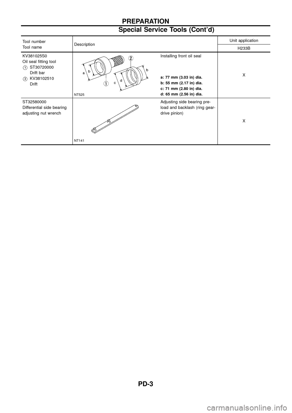
KV381025S0
Oil seal ®tting tool
V1ST30720000
Drift bar
V2KV38102510
Drift
NT525
Installing front oil seal
X
a: 77 mm (3.03 in) dia.
b: 55 mm (2.17 in) dia.
c: 71 mm (2.80 in) dia.
d: 65 mm (2.56 in) dia.
ST32580000
Differential side bearing
adjusting nut wrench
NT141
Adjusting side bearing pre-
load and backlash (ring gear-
drive pinion)
X
PREPARATION
Special Service Tools (Cont'd)
PD-3
Page 5 of 54
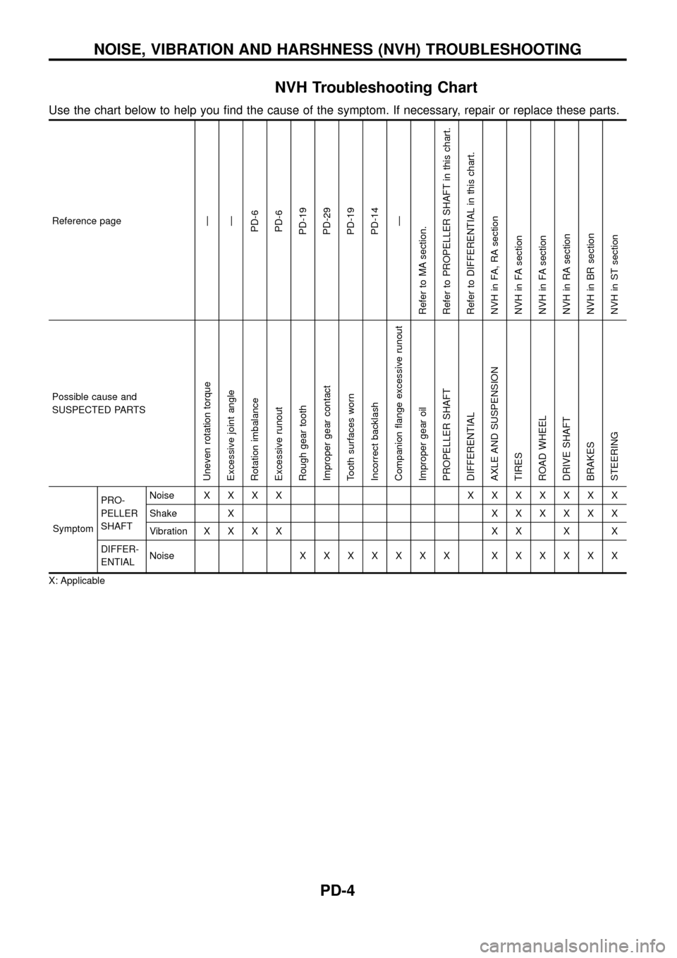
NVH Troubleshooting Chart
Use the chart below to help you ®nd the cause of the symptom. If necessary, repair or replace these parts.
Reference pageÐ
Ð
PD-6
PD-6
PD-19
PD-29
PD-19
PD-14
Ð
Refer to MA section.
Refer to PROPELLER SHAFT in this chart.
Refer to DIFFERENTIAL in this chart.
NVH in FA, RA section
NVH in FA section
NVH in FA section
NVH in RA section
NVH in BR section
NVH in ST section
Possible cause and
SUSPECTED PARTS
Uneven rotation torque
Excessive joint angle
Rotation imbalance
Excessive runout
Rough gear tooth
Improper gear contact
Tooth surfaces worn
Incorrect backlash
Companion ¯ange excessive runout
Improper gear oil
PROPELLER SHAFT
DIFFERENTIAL
AXLE AND SUSPENSION
TIRES
ROAD WHEEL
DRIVE SHAFT
BRAKES
STEERING
SymptomPRO-
PELLER
SHAFTNoiseXXXX XXXXXXX
Shake XXXXXXX
VibrationXXXX XX X X
DIFFER-
ENTIALNoiseXXXXXXX XXXXXX
X: Applicable
NOISE, VIBRATION AND HARSHNESS (NVH) TROUBLESHOOTING
PD-4
Page 16 of 54
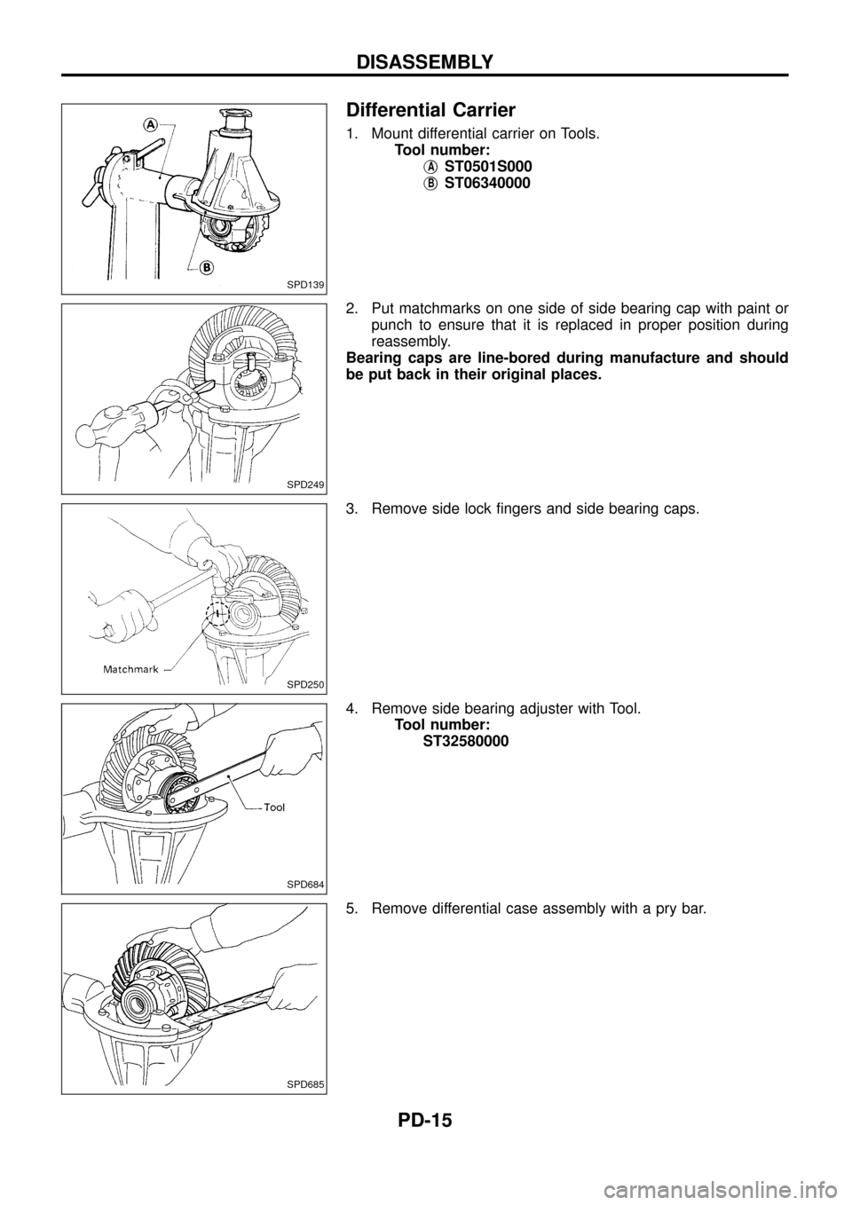
Differential Carrier
1. Mount differential carrier on Tools.
Tool number:
j
AST0501S000
j
BST06340000
2. Put matchmarks on one side of side bearing cap with paint or
punch to ensure that it is replaced in proper position during
reassembly.
Bearing caps are line-bored during manufacture and should
be put back in their original places.
3. Remove side lock ®ngers and side bearing caps.
4. Remove side bearing adjuster with Tool.
Tool number:
ST32580000
5. Remove differential case assembly with a pry bar.
SPD139
SPD249
SPD250
SPD684
SPD685
DISASSEMBLY
PD-15
Page 17 of 54
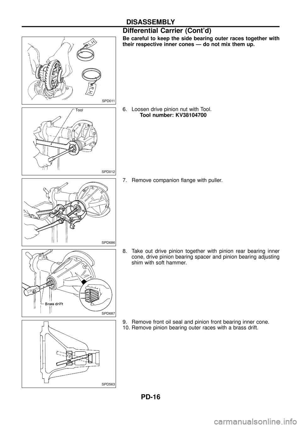
Be careful to keep the side bearing outer races together with
their respective inner cones Ð do not mix them up.
6. Loosen drive pinion nut with Tool.
Tool number: KV38104700
7. Remove companion ¯ange with puller.
8. Take out drive pinion together with pinion rear bearing inner
cone, drive pinion bearing spacer and pinion bearing adjusting
shim with soft hammer.
9. Remove front oil seal and pinion front bearing inner cone.
10. Remove pinion bearing outer races with a brass drift.
SPD011
SPD012
SPD686
SPD687
SPD563
DISASSEMBLY
Differential Carrier (Cont'd)
PD-16
Page 18 of 54
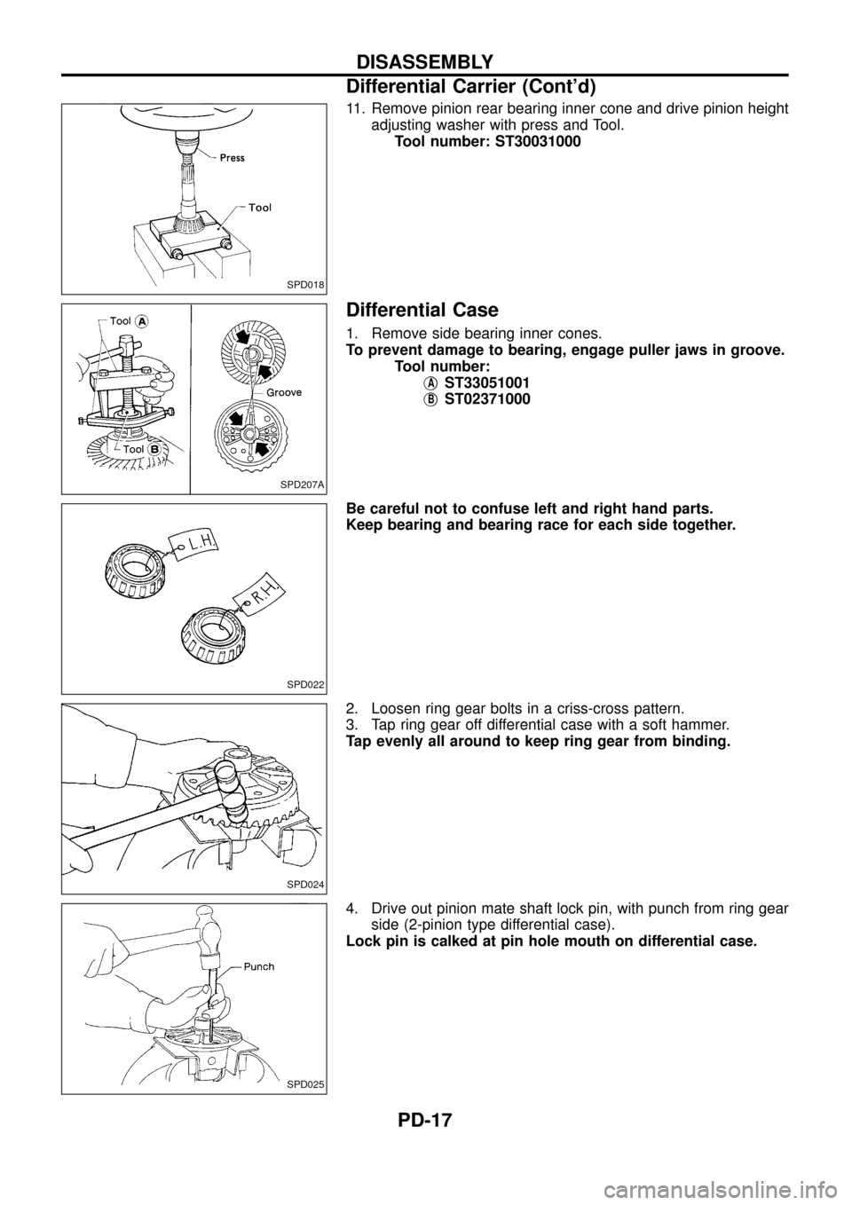
11. Remove pinion rear bearing inner cone and drive pinion height
adjusting washer with press and Tool.
Tool number: ST30031000
Differential Case
1. Remove side bearing inner cones.
To prevent damage to bearing, engage puller jaws in groove.
Tool number:
j
AST33051001
j
BST02371000
Be careful not to confuse left and right hand parts.
Keep bearing and bearing race for each side together.
2. Loosen ring gear bolts in a criss-cross pattern.
3. Tap ring gear off differential case with a soft hammer.
Tap evenly all around to keep ring gear from binding.
4. Drive out pinion mate shaft lock pin, with punch from ring gear
side (2-pinion type differential case).
Lock pin is calked at pin hole mouth on differential case.
SPD018
SPD207A
SPD022
SPD024
SPD025
DISASSEMBLY
Differential Carrier (Cont'd)
PD-17
Page 19 of 54
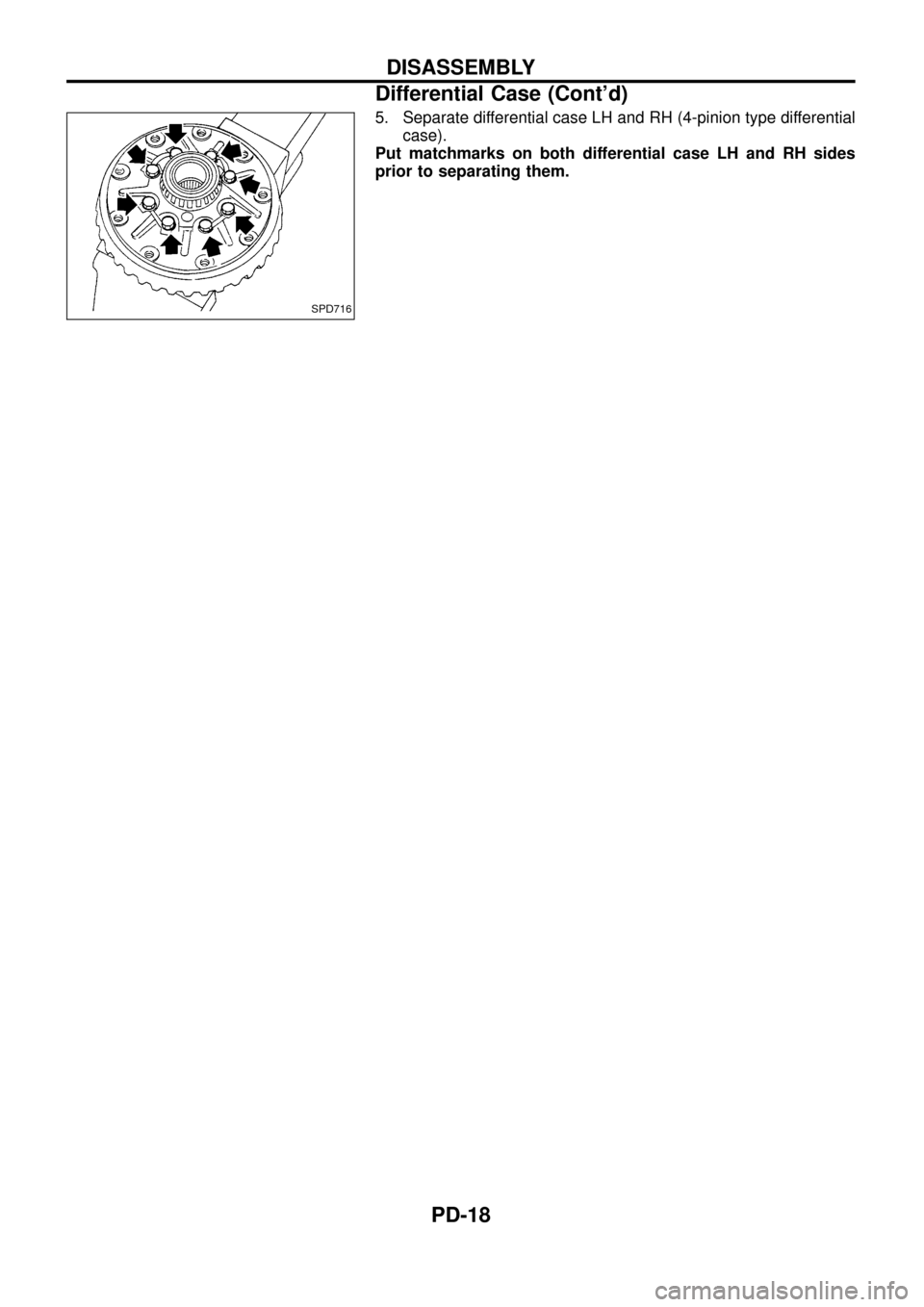
5. Separate differential case LH and RH (4-pinion type differential
case).
Put matchmarks on both differential case LH and RH sides
prior to separating them.
SPD716
DISASSEMBLY
Differential Case (Cont'd)
PD-18
Page 20 of 54
Ring Gear and Drive Pinion
Check gear teeth for scoring, cracking or chipping. If any damaged
part is evident, replace ring gear and drive pinion as a set (hypoid
gear set).
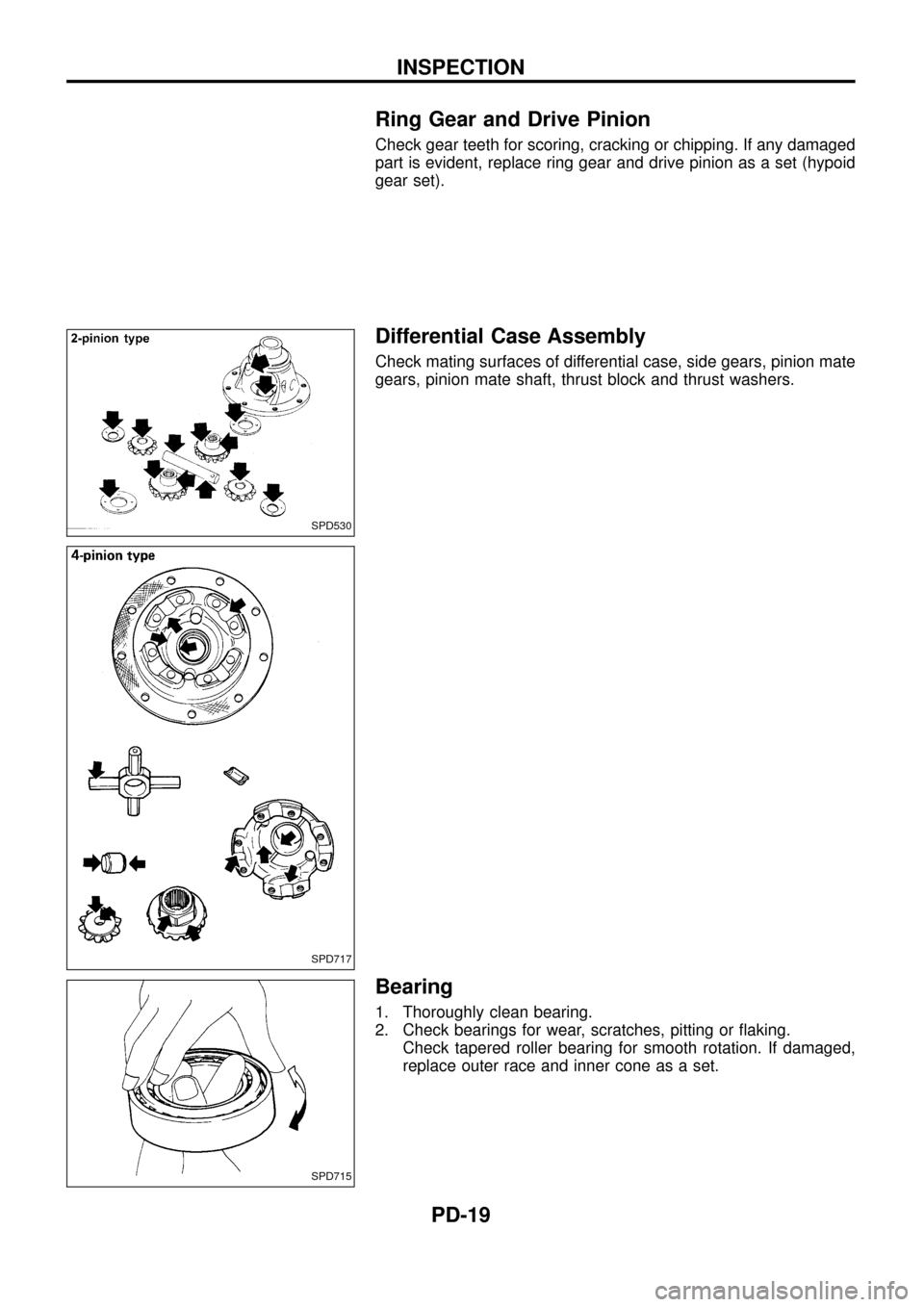
Differential Case Assembly
Check mating surfaces of differential case, side gears, pinion mate
gears, pinion mate shaft, thrust block and thrust washers.
Bearing
1. Thoroughly clean bearing.
2. Check bearings for wear, scratches, pitting or ¯aking.
Check tapered roller bearing for smooth rotation. If damaged,
replace outer race and inner cone as a set.
SPD530
SPD717
SPD715
INSPECTION
PD-19