NISSAN PATROL 2000 Electronic Repair Manual
Manufacturer: NISSAN, Model Year: 2000, Model line: PATROL, Model: NISSAN PATROL 2000Pages: 1033, PDF Size: 30.71 MB
Page 351 of 1033
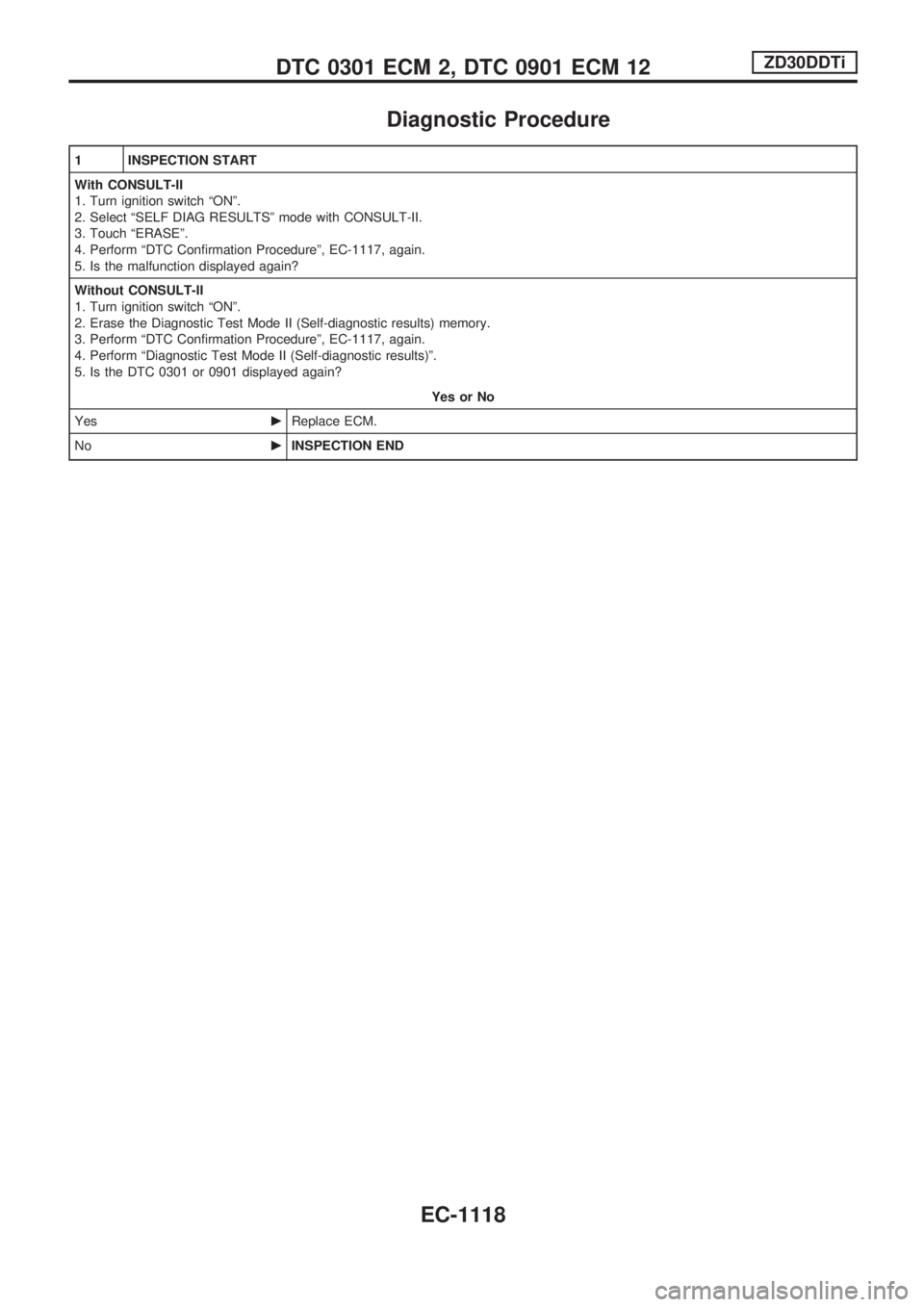
Diagnostic Procedure
1 INSPECTION START
With CONSULT-II
1. Turn ignition switch ªONº.
2. Select ªSELF DIAG RESULTSº mode with CONSULT-II.
3. Touch ªERASEº.
4. Perform ªDTC Confirmation Procedureº, EC-1117, again.
5. Is the malfunction displayed again?
Without CONSULT-II
1. Turn ignition switch ªONº.
2. Erase the Diagnostic Test Mode II (Self-diagnostic results) memory.
3. Perform ªDTC Confirmation Procedureº, EC-1117, again.
4. Perform ªDiagnostic Test Mode II (Self-diagnostic results)º.
5. Is the DTC 0301 or 0901 displayed again?
Yes or No
YescReplace ECM.
NocINSPECTION END
DTC 0301 ECM 2, DTC 0901 ECM 12ZD30DDTi
EC-1118
Page 352 of 1033

Description
SYSTEM DESCRIPTION
The ECM and the electronic control fuel injection pump control
unit (abbreviated as the injection pump control unit) perform the
real time communication (signal exchange).
The ECM transmits the signals of the target fuel injection
amount, target fuel injection timing, and engine speed, etc., and
receives the signals of the pump speed and fuel temperature,
etc. from the injection pump control unit.
By those signals, the injection pump controls the optimum fuel
injection amount and injection timing of the spill valve and tim-
ing control valve.
Injection pump control unit has an on board diagnostic system,
which detects malfunctions related to sensors or actuators built-
into electronic control fuel injection pump. These malfunction
information are transferred through the line (circuit) from injection
pump control unit to ECM.
FUEL INJECTION AMOUNT CONTROL
In accordance with the target fuel injection amount signal from
the ECM, the injection amount is controlled by controlling the spill
valve in the injection pump and by changing the needle opening
time.
FUEL INJECTION TIMING CONTROL
Based on the target fuel injection timing signal from the ECM, the
injection timing is controlled in accordance with the timer spring
by performing the duty control of the timing control valve in the
injection pump and by adjusting the pressure of the timer piston
high pressure chamber.
FUEL TEMPERATURE SENSOR
The sensor detects the fuel temperature in the injection pump
and calibrates the injection amount change by the fuel tempera-
ture.
CAM RING POSITION SENSOR
The sensor detects the passing of the protrusion on the sensor
wheel in the injection pump by the semiconductor magnetic
resistance element sensor. The cam ring position sensor syn-
chronizes with the cam ring, and detects the actual advance
amount. The injection pump control unit measures the injection
pump revolution by the signal of the cam ring position sensor.
SEF437Y
DTC 0402 P9zFUEL TEMP SENZD30DDTi
EC-1119
Page 353 of 1033

CONSULT-II Reference Value in Data Monitor
Mode
Remarks: Specification data are reference values.
MONITOR ITEM CONDITION SPECIFICATION
FUEL TEMP SEN+Engine: After warming up More than 40ÉC (104ÉF)
SPILL/V+Engine: After warming up Approx. 13ÉCA
INJ TIMG C/V+Engine: After warming up,
idle the engine.Approx. 50 - 70%
DECELER F/CUT+Engine: After warm-
ing upIdle OFF
BARO SEN+Ignition switch: ONAltitude
Approx.0m(0ft): Approx. 100.62 kPa (1.0062 bar, 1.026 kg/cm
2, 14.59
psi)
Approx. 1,000 m (3,281 ft): Approx. 88.95 kPa (0.8895 bar, 0.907 kg/cm
2,
12.90 psi)
Approx. 1,500 m (4,992 ft): Approx. 83.16 kPa (0.8316 bar, 0.848 kg/cm
2,
12.06 psi)
Approx. 2,000 m (6,562 ft): Approx. 78.36 kPa (0.7836 bar, 0.799 kg/cm
2,
11.36 psi)
ECM Terminals and Reference Value
Specification data are reference values and are measured between each terminal and ground.
CAUTION:
Do not use ECM ground terminals when measuring input/output voltage. Doing so may damage the
ECM's transistor. Use a ground other than ECM terminals, such as the ground.
TER-
MINAL
NO.WIRE
COLORITEM CONDITION DATA (DC Voltage)
33 G/YElectronic control fuel
injection pumpEngine is running.
Warm-up condition
Idle speedApproximately 2.5V
40 R/BElectronic control fuel
injection pumpEngine is running.
Warm-up condition
Idle speedApproximately 2.5V
52 L/BElectronic control fuel
injection pumpEngine is running.
Idle speedApproximately 0.1V
53 L/RElectronic control fuel
injection pumpEngine is running.
Idle speedApproximately 0.35V
On Board Diagnosis Logic
Malfunction is detected when .... Check Items (Possible cause)
+An improper voltage signal from fuel temperature sensor
(Built-into electronic control fuel injection pump) is sent to
injection pump control unit.+Harness or connectors
(Electronic control fuel injection pump circuit is open or
shorted.)
+Electronic control fuel injection pump
DTC 0402 P9zFUEL TEMP SENZD30DDTi
EC-1120
Page 354 of 1033
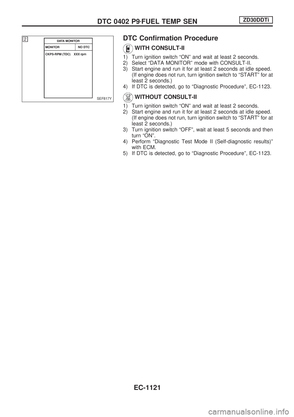
DTC Confirmation Procedure
WITH CONSULT-II
1) Turn ignition switch ªONº and wait at least 2 seconds.
2) Select ªDATA MONITORº mode with CONSULT-II.
3) Start engine and run it for at least 2 seconds at idle speed.
(If engine does not run, turn ignition switch to ªSTARTº for at
least 2 seconds.)
4) If DTC is detected, go to ªDiagnostic Procedureº, EC-1123.
WITHOUT CONSULT-II
1) Turn ignition switch ªONº and wait at least 2 seconds.
2) Start engine and run it for at least 2 seconds at idle speed.
(If engine does not run, turn ignition switch to ªSTARTº for at
least 2 seconds.)
3) Turn ignition switch ªOFFº, wait at least 5 seconds and then
turn ªONº.
4) Perform ªDiagnostic Test Mode II (Self-diagnostic results)º
with ECM.
5) If DTC is detected, go to ªDiagnostic Procedureº, EC-1123.
SEF817Y
DTC 0402 P9zFUEL TEMP SENZD30DDTi
EC-1121
Page 355 of 1033
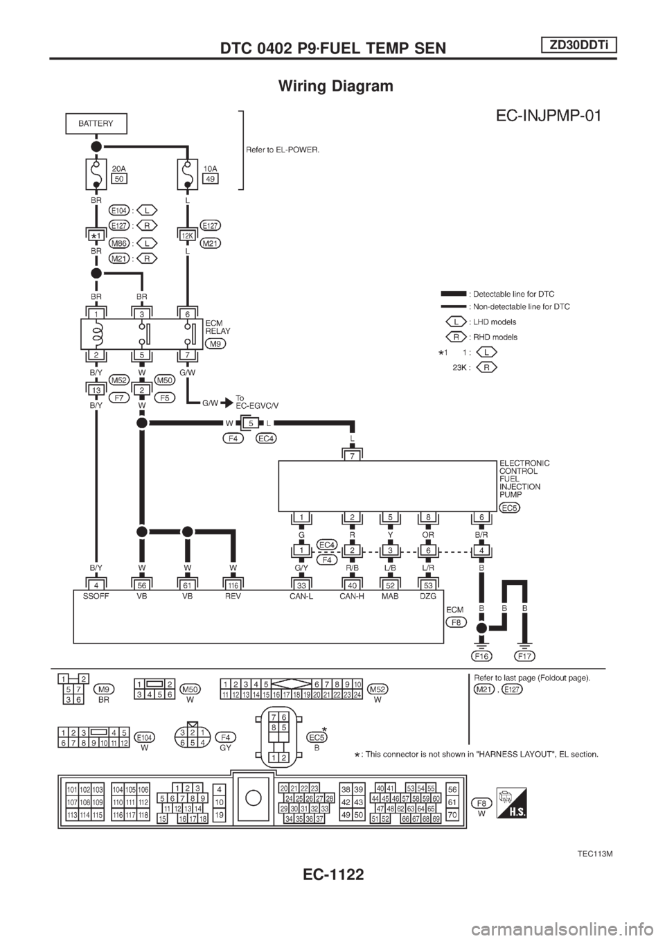
Wiring Diagram
TEC113M
DTC 0402 P9zFUEL TEMP SENZD30DDTi
EC-1122
Page 356 of 1033

Diagnostic Procedure
1 CHECK ELECTRONIC CONTROL FUEL INJECTION PUMP POWER SUPPLY CIRCUIT
1. Turn ignition switch ªOFFº.
2. Disconnect electronic control fuel injection pump harness connector.
SEF229Z
3. Turn ignition switch ªONº.
4. Check voltage between electronic control fuel injection pump terminal 7 and ground.
SEF438Y
OK or NG
OKcGO TO 3.
NGcGO TO 2.
2 DETECT MALFUNCTIONING PART
Check the following.
+Harness connectors M50, F5
+Harness connectors F4, EC4
+Harness for open or short between electronic control fuel injection pump and ECM
+Harness for open or short between electronic control fuel injection pump and ECM relay
cRepair open circuit or short to ground or short to power in harness or connectors.
3 CHECK ELECTRONIC CONTROL FUEL INJECTION PUMP GROUND CIRCUIT FOR OPEN AND SHORT
1. Turn ignition switch ªOFFº.
2. Check harness continuity between electronic control fuel injection pump terminal 6 and ground. Refer to Wiring Diagram.
Continuity should exist.
3. Also check harness for short to ground and short to power.
OK or NG
OKcGO TO 5.
NGcGO TO 4.
DTC 0402 P9zFUEL TEMP SENZD30DDTi
EC-1123
Page 357 of 1033
4 DETECT MALFUNCTIONING PART
Check the following.
+Harness connectors F4, EC4
+Harness for open or short between electronic control fuel injection pump and engine ground
cRepair open circuit or short to ground or short to power in harness or connectors.
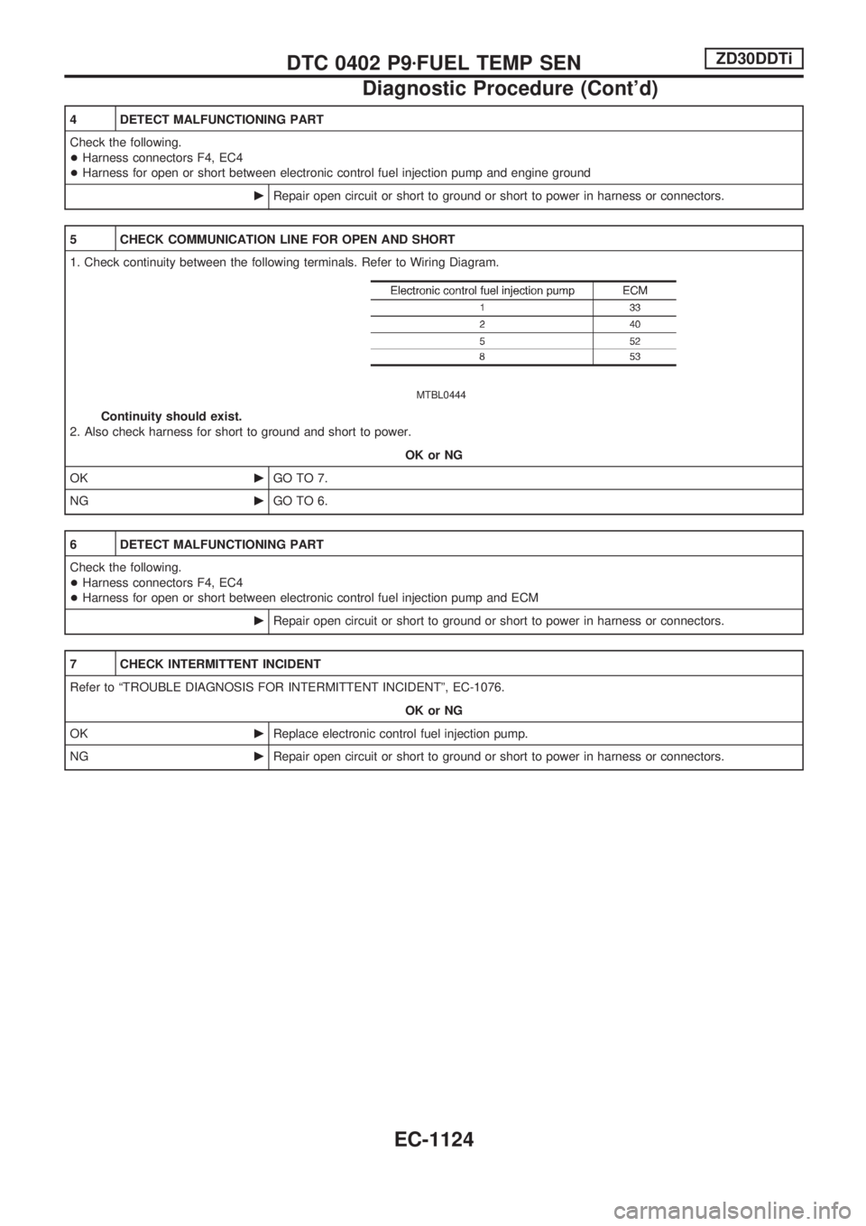
5 CHECK COMMUNICATION LINE FOR OPEN AND SHORT
1. Check continuity between the following terminals. Refer to Wiring Diagram.
MTBL0444
Continuity should exist.
2. Also check harness for short to ground and short to power.
OK or NG
OKcGO TO 7.
NGcGO TO 6.
6 DETECT MALFUNCTIONING PART
Check the following.
+Harness connectors F4, EC4
+Harness for open or short between electronic control fuel injection pump and ECM
cRepair open circuit or short to ground or short to power in harness or connectors.
7 CHECK INTERMITTENT INCIDENT
Refer to ªTROUBLE DIAGNOSIS FOR INTERMITTENT INCIDENTº, EC-1076.
OK or NG
OKcReplace electronic control fuel injection pump.
NGcRepair open circuit or short to ground or short to power in harness or connectors.
DTC 0402 P9zFUEL TEMP SENZD30DDTi
Diagnostic Procedure (Cont'd)
EC-1124
Page 358 of 1033
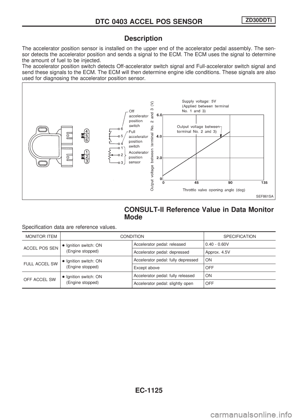
Description
The accelerator position sensor is installed on the upper end of the accelerator pedal assembly. The sen-
sor detects the accelerator position and sends a signal to the ECM. The ECM uses the signal to determine
the amount of fuel to be injected.
The accelerator position switch detects Off-accelerator switch signal and Full-accelerator switch signal and
send these signals to the ECM. The ECM will then determine engine idle conditions. These signals are also
used for diagnosing the accelerator position sensor.
CONSULT-II Reference Value in Data Monitor
Mode
Specification data are reference values.
MONITOR ITEM CONDITION SPECIFICATION
ACCEL POS SEN+Ignition switch: ON
(Engine stopped)Accelerator pedal: released 0.40 - 0.60V
Accelerator pedal: depressed Approx. 4.5V
FULL ACCEL SW+Ignition switch: ON
(Engine stopped)Accelerator pedal: fully depressed ON
Except above OFF
OFF ACCEL SW+Ignition switch: ON
(Engine stopped)Accelerator pedal: fully released ON
Accelerator pedal: slightly open OFF
SEF861SA
DTC 0403 ACCEL POS SENSORZD30DDTi
EC-1125
Page 359 of 1033

ECM Terminals and Reference Value
Specification data are reference values and are measured between each terminal and ground.
CAUTION:
Do not use ECM ground terminals when measuring input/output voltage. Doing so may damage the
ECM's transistor. Use a ground other than ECM terminals, such as the ground.
TER-
MINAL
NO.WIRE
COLORITEM CONDITION DATA (DC Voltage)
23 WAccelerator position sen-
sorIgnition switch ªONº
Accelerator pedal fully released0.4 - 0.6V
Ignition switch ªONº
Accelerator pedal fully depressedApproximately 4.5V
31 R/LAccelerator position switch
(Idle)Ignition switch ªONº
Accelerator pedal fully releasedBATTERY VOLTAGE
(11 - 14V)
Ignition switch ªONº
Accelerator pedal depressedApproximately 0V
32 W/GAccelerator position switch
(Full)Ignition switch ªONº
Accelerator pedal releasedApproximately 0V
Ignition switch ªONº
Accelerator pedal fully depressedBATTERY VOLTAGE
(11 - 14V)
48 G/RAccelerator position sen-
sor power supplyIgnition switch ªONº
Approximately 5V
51 L/WAccelerator position sen-
sor groundEngine is running.
Warm-up condition
Idle speedApproximately 0V
On Board Diagnosis Logic
Malfunction is detected when ... Check Items (Possible Cause)
+The relation between sensor and switch signal is not in the
normal range during the specified accelerator position.+Harness or connectors
(The sensor circuit is open or shorted.)
+Accelerator position sensor
+Accelerator position switch
+Accelerator switch (F/C)
DTC 0403 ACCEL POS SENSORZD30DDTi
EC-1126
Page 360 of 1033
DTC Confirmation Procedure
WITH CONSULT-II
1) Turn ignition switch ªONº.
2) Select ªDATA MONITORº mode with CONSULT-II.
3) Depress and release fully accelerator pedal slowly.
4) If DTC is detected, go to ªDiagnostic Procedureº, EC-1130.
WITHOUT CONSULT-II
1) Turn ignition switch ªONº.
2) Depress and release fully accelerator pedal slowly.
3) Turn ignition switch ªOFFº, wait at least 5 seconds and then
turn ªONº.
4) Perform ªDiagnostic Test Mode II (Self-diagnostic results)º
with ECM.
5) If DTC is detected, go to ªDiagnostic Procedureº, EC-1130.SEF817Y
DTC 0403 ACCEL POS SENSORZD30DDTi
EC-1127