NISSAN PATROL 2000 Electronic Repair Manual
[x] Cancel search | Manufacturer: NISSAN, Model Year: 2000, Model line: PATROL, Model: NISSAN PATROL 2000Pages: 1033, PDF Size: 30.71 MB
Page 461 of 1033
14 DETECT MALFUNCTIONING PART
Check the following.
+Harness connectors E127, M21
+Harness connectors M51, F6
+Harness for open or short between glow relay and ECM
cRepair open circuit or short to ground or short to power in harness or connectors.
15 CHECK HARNESS CONTINUITY BETWEEN GLOW RELAY AND GLOW PLUG FOR OPEN AND SHORT
1. Disconnect glow plug harness connector.
2. Check harness continuity between glow relay terminal 5 and glow plug harness connector. Refer to Wiring Diagram.
Continuity should exist.
3. Also check harness for short to ground and short to power.
OK or NG
OKcGO TO 16.
NGcRepair open circuit or short to ground or short to power in harness or connectors.
16 DETECT MALFUNCTIONING PART
Check the following.
+Harness connectors E67, E223
+Harness connectors E225, E241
+Harness for open or short between glow relay and glow plug
cRepair open circuit or short to ground or short to power in harness or connectors.
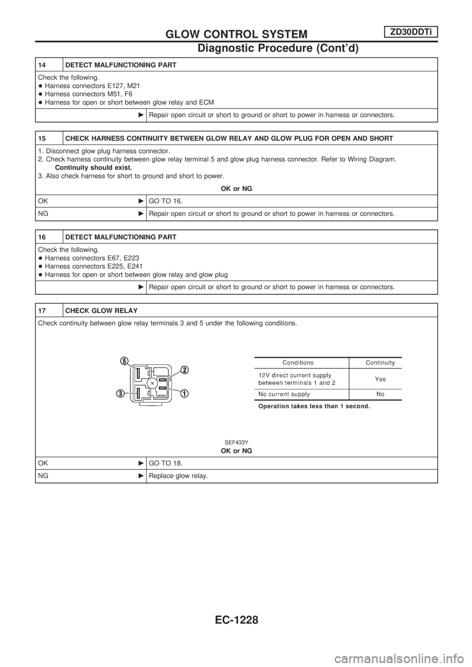
17 CHECK GLOW RELAY
Check continuity between glow relay terminals 3 and 5 under the following conditions.
SEF433Y
OK or NG
OKcGO TO 18.
NGcReplace glow relay.
GLOW CONTROL SYSTEMZD30DDTi
Diagnostic Procedure (Cont'd)
EC-1228
Page 462 of 1033

18 CHECK GLOW PLUG
1. Remove glow plug connecting plate.
2. Check glow plug resistance.
SEF236Z
NOTE:
+Do not bump glow plug heating element. If it is bumped, replace glow plug with a new one.
+If glow plug is dropped from a height of 10 cm (3.94 in) or higher, replace with a new one.
+If glow plug installation hole is contaminated with carbon, remove it with a reamer or suitable tool.
+Hand-tighten glow plug by turning it two or three times, then tighten using a tool to specified torque.
:15-20Nzm (1.5 - 2.1 kg-m, 11 - 15 ft-lb)
OK or NG
OKcGO TO 19.
NGcReplace glow plug.
19 CHECK INTERMITTENT INCIDENT
Refer to ªTROUBLE DIAGNOSIS FOR INTERMITTENT INCIDENTº, EC-1076.
cINSPECTION END
GLOW CONTROL SYSTEMZD30DDTi
Diagnostic Procedure (Cont'd)
EC-1229
Page 463 of 1033
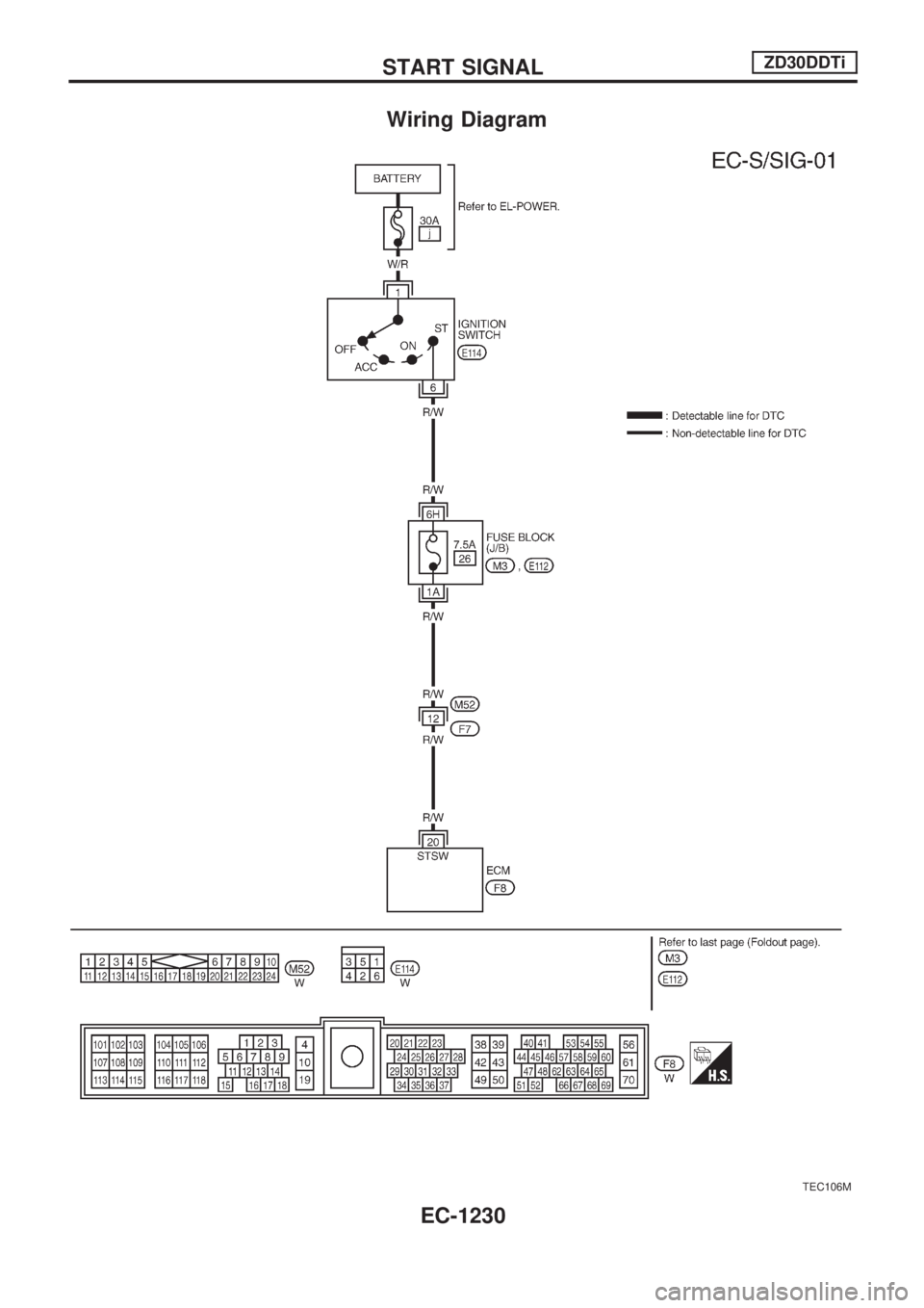
Wiring Diagram
TEC106M
START SIGNALZD30DDTi
EC-1230
Page 464 of 1033
Diagnostic Procedure
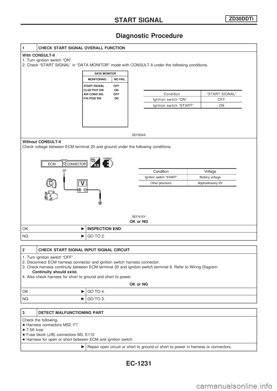
1 CHECK START SIGNAL OVERALL FUNCTION
With CONSULT-II
1. Turn ignition switch ªONº.
2. Check ªSTART SIGNALº in ªDATA MONITORº mode with CONSULT-II under the following conditions.
SEF604X
Without CONSULT-II
Check voltage between ECM terminal 20 and ground under the following conditions.
SEF415Y
OK or NG
OKcINSPECTION END
NGcGO TO 2.
2 CHECK START SIGNAL INPUT SIGNAL CIRCUIT
1. Turn ignition switch ªOFFº.
2. Disconnect ECM harness connector and ignition switch harness connector.
3. Check harness continuity between ECM terminal 20 and ignition switch terminal 6. Refer to Wiring Diagram.
Continuity should exist.
4. Also check harness for short to ground and short to power.
OK or NG
OKcGO TO 4.
NGcGO TO 3.
3 DETECT MALFUNCTIONING PART
Check the following.
+Harness connectors M52, F7
+7.5A fuse
+Fuse block (J/B) connectors M3, E112
+Harness for open or short between ECM and ignition switch
cRepair open circuit or short to ground or short to power in harness or connectors.
START SIGNALZD30DDTi
EC-1231
Page 465 of 1033

4 CHECK INTERMITTENT INCIDENT
Refer to ªTROUBLE DIAGNOSIS FOR INTERMITTENT INCIDENTº, EC-1076.
cINSPECTION END
START SIGNALZD30DDTi
Diagnostic Procedure (Cont'd)
EC-1232
Page 466 of 1033
Description
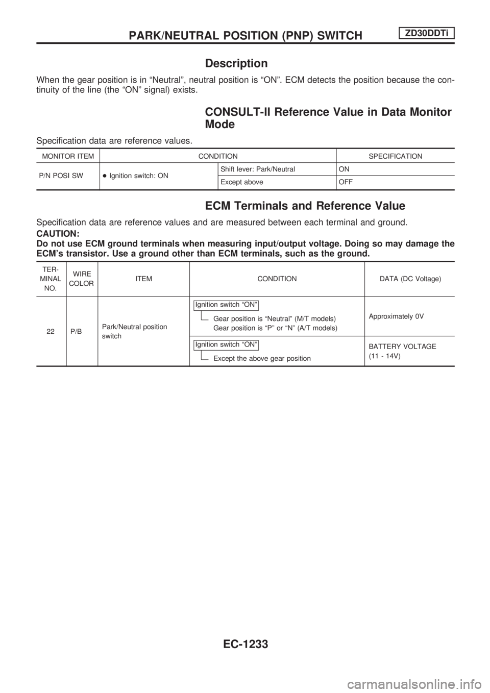
When the gear position is in ªNeutralº, neutral position is ªONº. ECM detects the position because the con-
tinuity of the line (the ªONº signal) exists.
CONSULT-II Reference Value in Data Monitor
Mode
Specification data are reference values.
MONITOR ITEM CONDITION SPECIFICATION
P/N POSI SW+Ignition switch: ONShift lever: Park/Neutral ON
Except above OFF
ECM Terminals and Reference Value
Specification data are reference values and are measured between each terminal and ground.
CAUTION:
Do not use ECM ground terminals when measuring input/output voltage. Doing so may damage the
ECM's transistor. Use a ground other than ECM terminals, such as the ground.
TER-
MINAL
NO.WIRE
COLORITEM CONDITION DATA (DC Voltage)
22 P/BPark/Neutral position
switchIgnition switch ªONº
Gear position is ªNeutralº (M/T models)
Gear position is ªPº or ªNº (A/T models)Approximately 0V
Ignition switch ªONº
Except the above gear positionBATTERY VOLTAGE
(11 - 14V)
PARK/NEUTRAL POSITION (PNP) SWITCHZD30DDTi
EC-1233
Page 467 of 1033
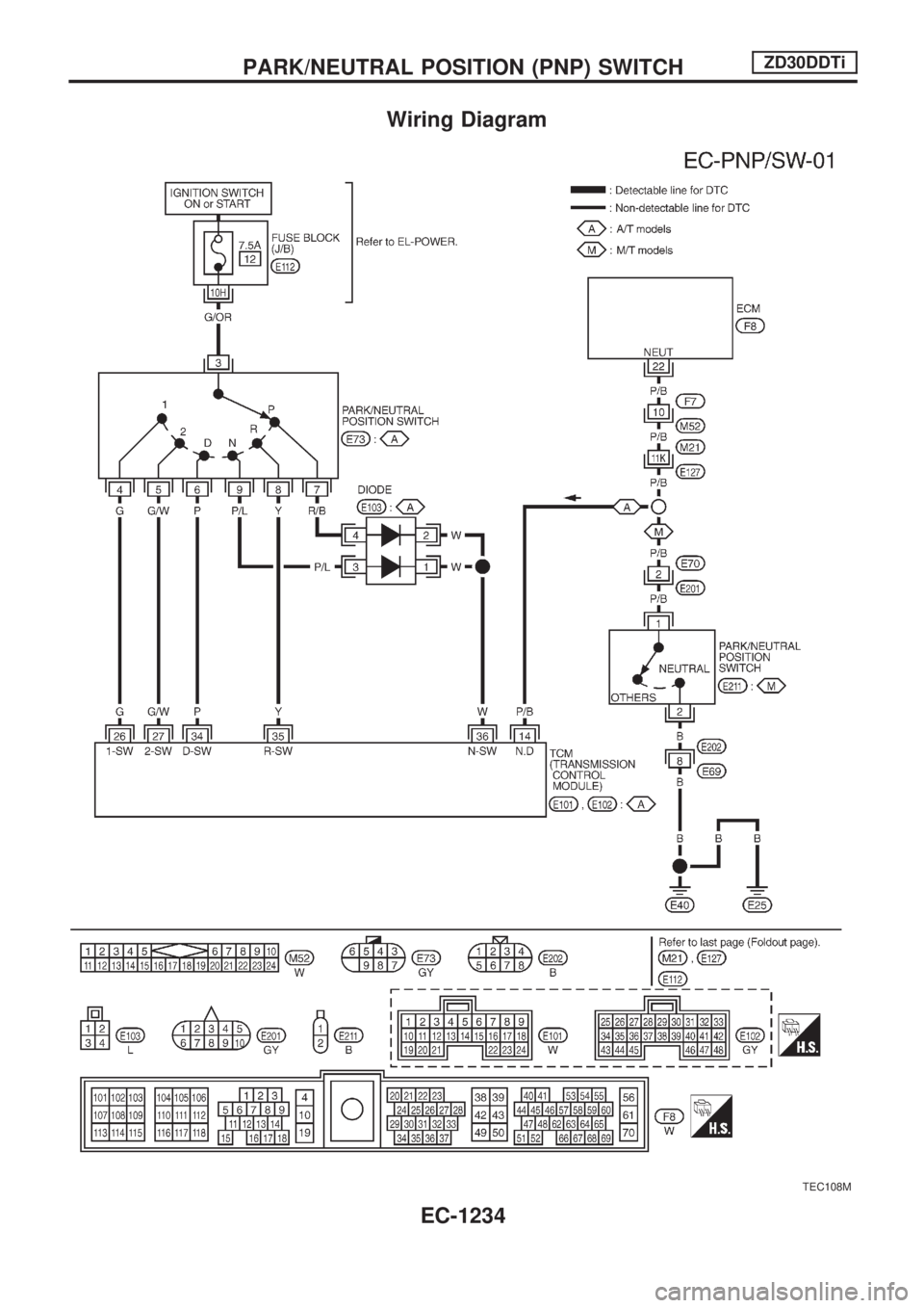
Wiring Diagram
TEC108M
PARK/NEUTRAL POSITION (PNP) SWITCHZD30DDTi
EC-1234
Page 468 of 1033
Diagnostic Procedure
FOR M/T MODELS
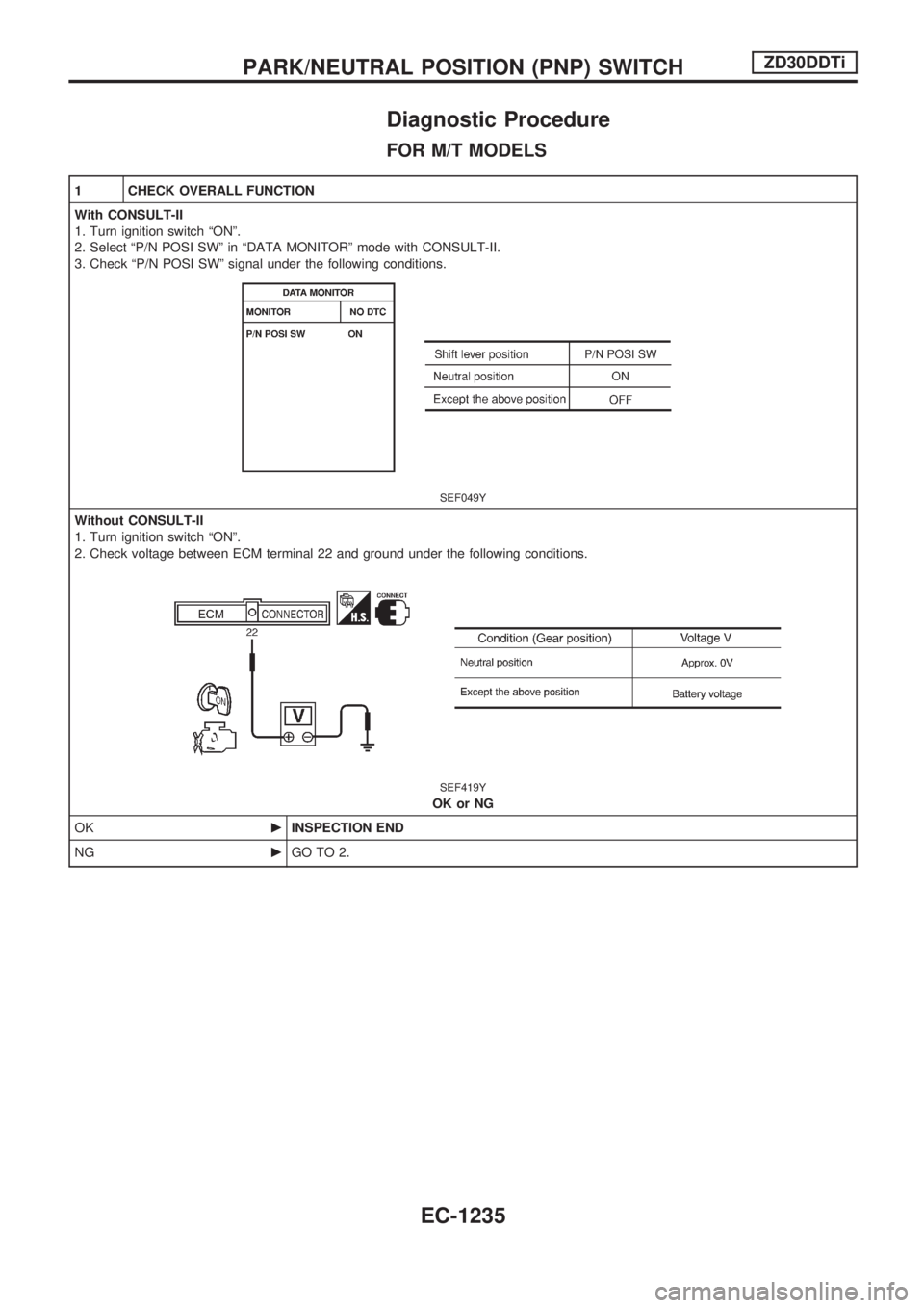
1 CHECK OVERALL FUNCTION
With CONSULT-II
1. Turn ignition switch ªONº.
2. Select ªP/N POSI SWº in ªDATA MONITORº mode with CONSULT-II.
3. Check ªP/N POSI SWº signal under the following conditions.
SEF049Y
Without CONSULT-II
1. Turn ignition switch ªONº.
2. Check voltage between ECM terminal 22 and ground under the following conditions.
SEF419Y
OK or NG
OKcINSPECTION END
NGcGO TO 2.
PARK/NEUTRAL POSITION (PNP) SWITCHZD30DDTi
EC-1235
Page 469 of 1033
2 CHECK PNP SWITCH GROUND CIRCUIT FOR OPEN AND SHORT
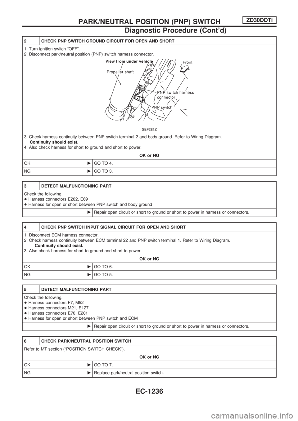
1. Turn ignition switch ªOFFº.
2. Disconnect park/neutral position (PNP) switch harness connector.
SEF281Z
3. Check harness continuity between PNP switch terminal 2 and body ground. Refer to Wiring Diagram.
Continuity should exist.
4. Also check harness for short to ground and short to power.
OK or NG
OKcGO TO 4.
NGcGO TO 3.
3 DETECT MALFUNCTIONING PART
Check the following.
+Harness connectors E202, E69
+Harness for open or short between PNP switch and body ground
cRepair open circuit or short to ground or short to power in harness or connectors.
4 CHECK PNP SWITCH INPUT SIGNAL CIRCUIT FOR OPEN AND SHORT
1. Disconnect ECM harness connector.
2. Check harness continuity between ECM terminal 22 and PNP switch terminal 1. Refer to Wiring Diagram.
Continuity should exist.
3. Also check harness for short to ground and short to power.
OK or NG
OKcGO TO 6.
NGcGO TO 5.
5 DETECT MALFUNCTIONING PART
Check the following.
+Harness connectors F7, M52
+Harness connectors M21, E127
+Harness connectors E70, E201
+Harness for open or short between PNP switch and ECM
cRepair open circuit or short to ground or short to power in harness or connectors.
6 CHECK PARK/NEUTRAL POSITION SWITCH
Refer to MT section (ªPOSITION SWITCH CHECKº).
OK or NG
OKcGO TO 7.
NGcReplace park/neutral position switch.
PARK/NEUTRAL POSITION (PNP) SWITCHZD30DDTi
Diagnostic Procedure (Cont'd)
EC-1236
Page 470 of 1033
7 CHECK INTERMITTENT INCIDENT
Refer to ªTROUBLE DIAGNOSIS FOR INTERMITTENT INCIDENTº, EC-1076.
cINSPECTION END
FOR A/T MODELS
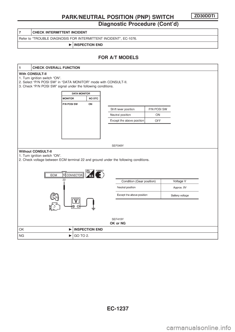
1 CHECK OVERALL FUNCTION
With CONSULT-II
1. Turn ignition switch ªONº.
2. Select ªP/N POSI SWº in ªDATA MONITORº mode with CONSULT-II.
3. Check ªP/N POSI SWº signal under the following conditions.
SEF049Y
Without CONSULT-II
1. Turn ignition switch ªONº.
2. Check voltage between ECM terminal 22 and ground under the following conditions.
SEF419Y
OK or NG
OKcINSPECTION END
NGcGO TO 2.
PARK/NEUTRAL POSITION (PNP) SWITCHZD30DDTi
Diagnostic Procedure (Cont'd)
EC-1237