NISSAN PATROL 2006 Service Manual
Manufacturer: NISSAN, Model Year: 2006, Model line: PATROL, Model: NISSAN PATROL 2006Pages: 1226, PDF Size: 37.18 MB
Page 1001 of 1226
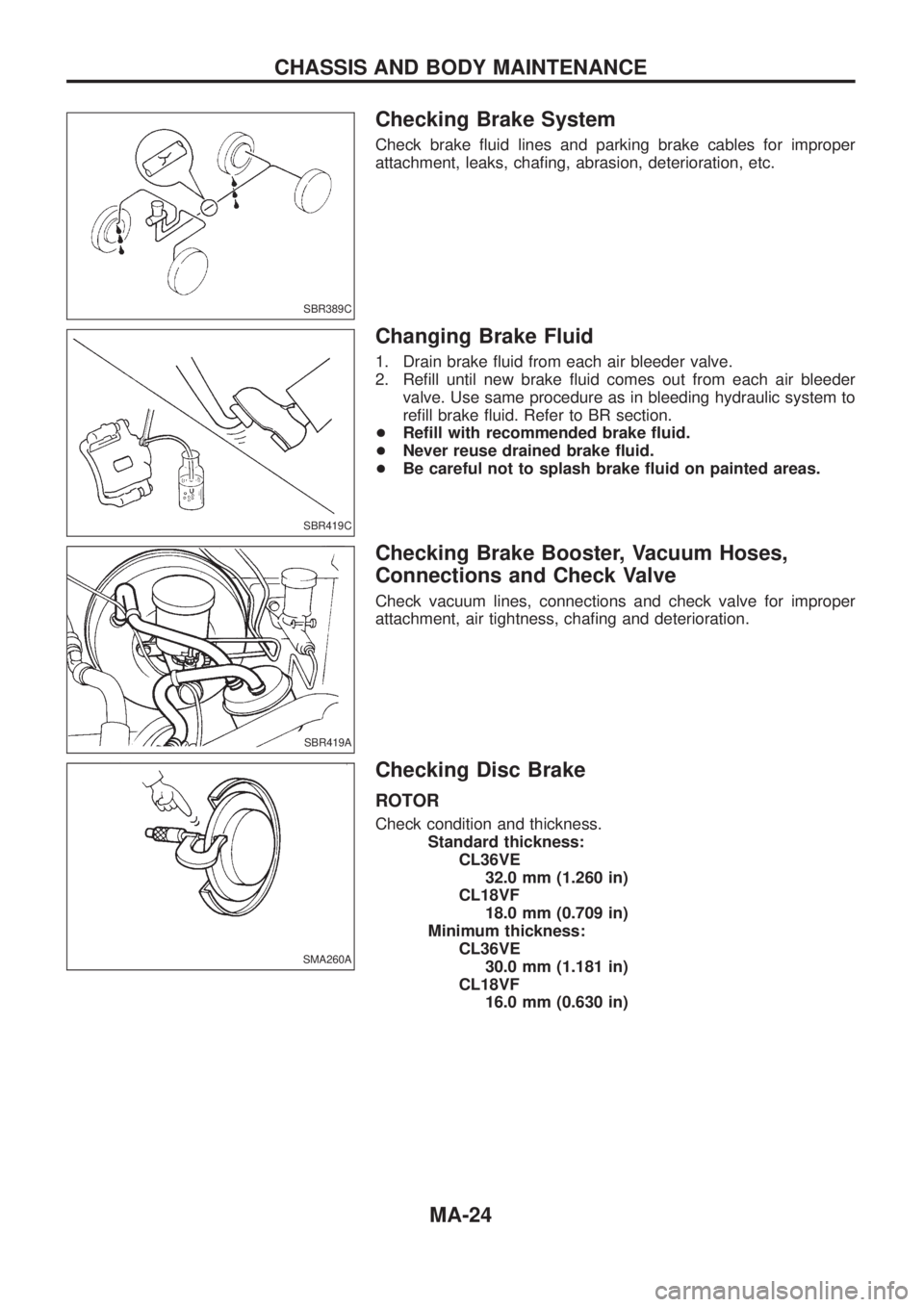
Checking Brake System
Check brake ¯uid lines and parking brake cables for improper
attachment, leaks, cha®ng, abrasion, deterioration, etc.
Changing Brake Fluid
1. Drain brake ¯uid from each air bleeder valve.
2. Re®ll until new brake ¯uid comes out from each air bleeder
valve. Use same procedure as in bleeding hydraulic system to
re®ll brake ¯uid. Refer to BR section.
+Re®ll with recommended brake ¯uid.
+Never reuse drained brake ¯uid.
+Be careful not to splash brake ¯uid on painted areas.
Checking Brake Booster, Vacuum Hoses,
Connections and Check Valve
Check vacuum lines, connections and check valve for improper
attachment, air tightness, cha®ng and deterioration.
Checking Disc Brake
ROTOR
Check condition and thickness.
Standard thickness:
CL36VE
32.0 mm (1.260 in)
CL18VF
18.0 mm (0.709 in)
Minimum thickness:
CL36VE
30.0 mm (1.181 in)
CL18VF
16.0 mm (0.630 in)
SBR389C
SBR419C
SBR419A
SMA260A
CHASSIS AND BODY MAINTENANCE
MA-24
Page 1002 of 1226
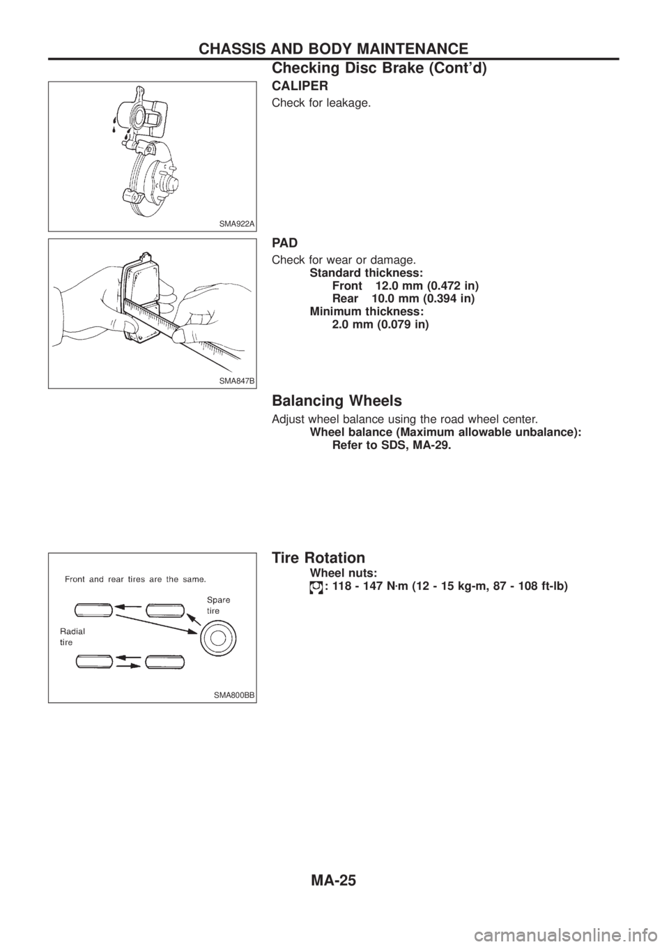
CALIPER
Check for leakage.
PA D
Check for wear or damage.
Standard thickness:
Front 12.0 mm (0.472 in)
Rear 10.0 mm (0.394 in)
Minimum thickness:
2.0 mm (0.079 in)
Balancing Wheels
Adjust wheel balance using the road wheel center.
Wheel balance (Maximum allowable unbalance):
Refer to SDS, MA-29.
Tire Rotation
Wheel nuts:
: 118 - 147 Nzm (12 - 15 kg-m, 87 - 108 ft-lb)
SMA922A
SMA847B
SMA800BB
CHASSIS AND BODY MAINTENANCE
Checking Disc Brake (Cont'd)
MA-25
Page 1003 of 1226
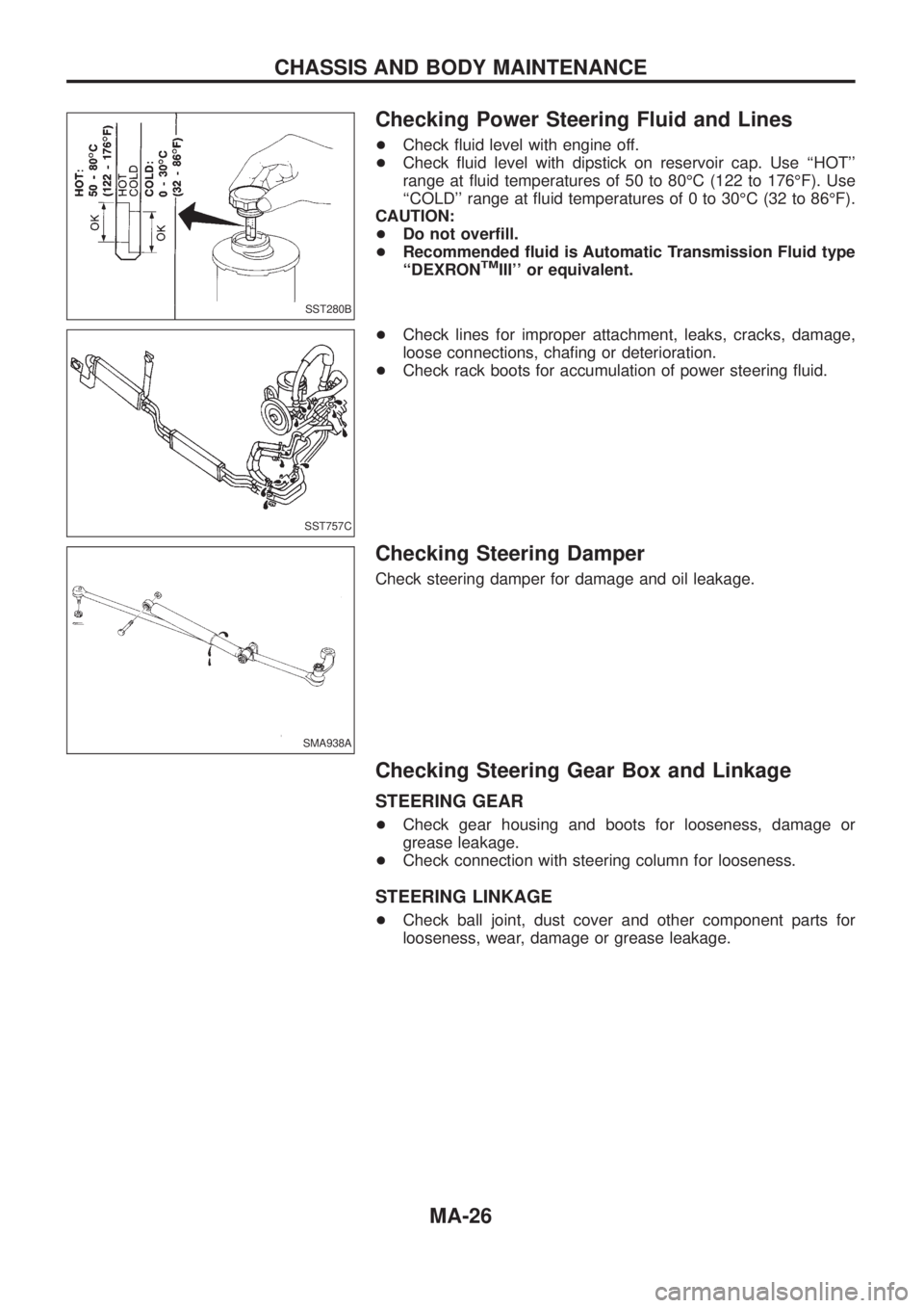
Checking Power Steering Fluid and Lines
+Check ¯uid level with engine off.
+Check ¯uid level with dipstick on reservoir cap. Use ``HOT''
range at ¯uid temperatures of 50 to 80ÉC (122 to 176ÉF). Use
``COLD'' range at ¯uid temperatures of 0 to 30ÉC (32 to 86ÉF).
CAUTION:
+Do not over®ll.
+Recommended ¯uid is Automatic Transmission Fluid type
``DEXRON
TMIII'' or equivalent.
+Check lines for improper attachment, leaks, cracks, damage,
loose connections, cha®ng or deterioration.
+Check rack boots for accumulation of power steering ¯uid.
Checking Steering Damper
Check steering damper for damage and oil leakage.
Checking Steering Gear Box and Linkage
STEERING GEAR
+Check gear housing and boots for looseness, damage or
grease leakage.
+Check connection with steering column for looseness.
STEERING LINKAGE
+Check ball joint, dust cover and other component parts for
looseness, wear, damage or grease leakage.
SST280B
SST757C
SMA938A
CHASSIS AND BODY MAINTENANCE
MA-26
Page 1004 of 1226
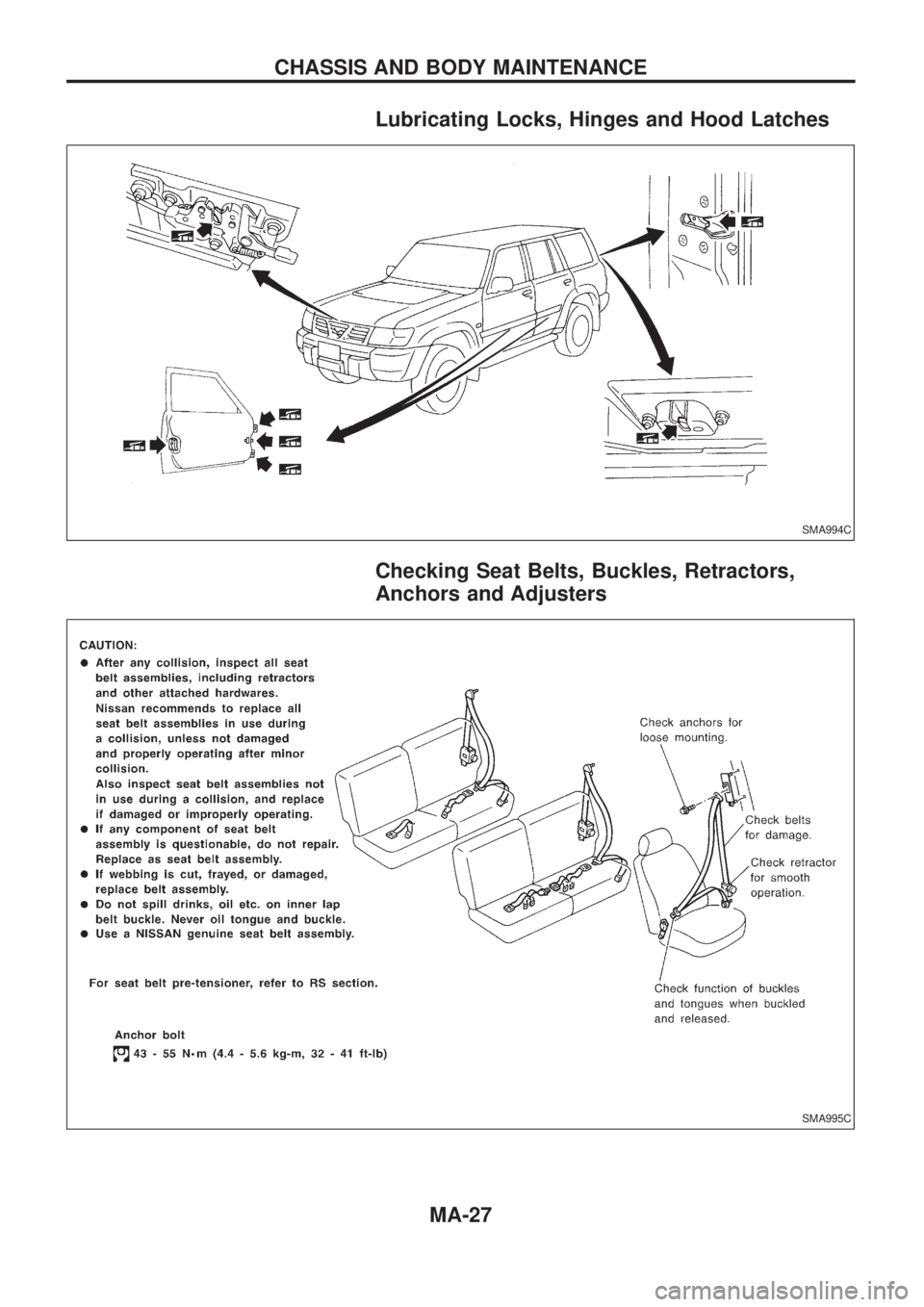
Lubricating Locks, Hinges and Hood Latches
Checking Seat Belts, Buckles, Retractors,
Anchors and Adjusters
SMA994C
SMA995C
CHASSIS AND BODY MAINTENANCE
MA-27
Page 1005 of 1226
Checking Body Corrosion
Visually check the body sheet metal panel for corrosion, paint damage (scratches, chipping, rubbing, etc.) or
damage to the anti-corrosion materials. In particular, check the following locations.
Hemmed portion
Hood front end, door lower end, trunk lid rear end, etc.
Panel joint
Side sill of rear fender and center pillar, rear wheel housing of rear fender, around strut tower in engine
compartment, etc.
Panel edge
Trunk lid opening, sunroof opening, fender wheelarch ¯ange, fuel ®ller lid ¯ange, around holes in panel, etc.
Parts contact
Waist molding, windshield molding, bumper, etc.
Protectors
Damage or condition of mudguard, fender protector, chipping protector, etc.
Anti-corrosion materials
Damage or separation of anti-corrosion materials under the body.
Drain holes
Condition of drain holes at door and side sill.
When repairing corroded areas, refer to the Corrosion Repair Manual.
CHASSIS AND BODY MAINTENANCE
MA-28
Page 1006 of 1226
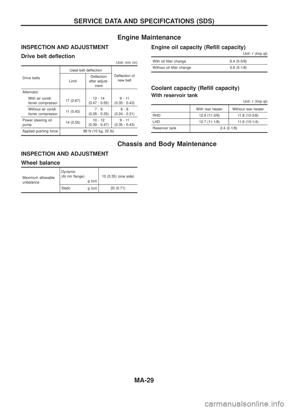
Engine Maintenance
INSPECTION AND ADJUSTMENT
Drive belt de¯ection
Unit: mm (in)
Drive beltsUsed belt de¯ection
De¯ection of
new belt
LimitDe¯ection
after adjust-
ment
Alternator
With air condi-
tioner compressor17 (0.67)12-14
(0.47 - 0.55)9-11
(0.35 - 0.43)
Without air condi-
tioner compressor11 (0.43)7-9
(0.28 - 0.35)6-8
(0.24 - 0.31)
Power steering oil
pump14 (0.55)10-12
(0.39 - 0.47)9-11
(0.35 - 0.43)
Applied pushing force 98 N (10 kg, 22 lb)
Engine oil capacity (Re®ll capacity)
Unit:!(Imp qt)
With oil ®lter change 6.4 (5-5/8)
Without oil ®lter change 5.8 (5-1/8)
Coolant capacity (Re®ll capacity)
With reservoir tank
Unit:!(Imp qt)
With rear heater Without rear heater
RHD 12.9 (11-3/8) 11.8 (10-3/8)
LHD 12.7 (11-1/8) 11.6 (10-1/4)
Reservoir tank 2.4 (2-1/8)
Chassis and Body Maintenance
INSPECTION AND ADJUSTMENT
Wheel balance
Maximum allowable
unbalanceDynamic
(At rim ¯ange)
g (oz)10 (0.35) (one side)
Static g (oz) 20 (0.71)
SERVICE DATA AND SPECIFICATIONS (SDS)
MA-29
Page 1007 of 1226
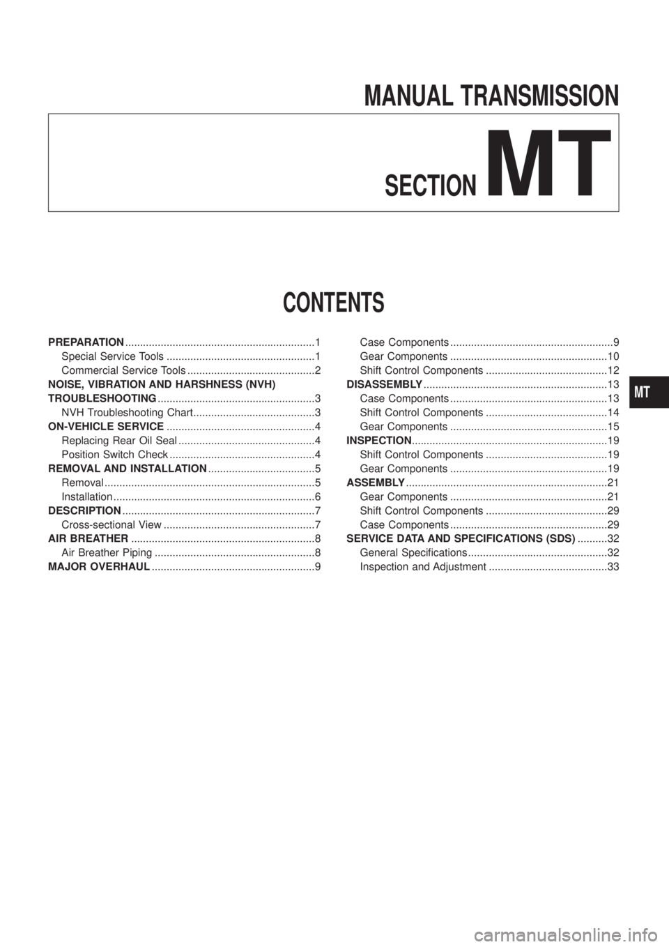
MANUAL TRANSMISSION
SECTION
MT
CONTENTS
PREPARATION................................................................1
Special Service Tools ..................................................1
Commercial Service Tools ...........................................2
NOISE, VIBRATION AND HARSHNESS (NVH)
TROUBLESHOOTING.....................................................3
NVH Troubleshooting Chart.........................................3
ON-VEHICLE SERVICE..................................................4
Replacing Rear Oil Seal ..............................................4
Position Switch Check .................................................4
REMOVAL AND INSTALLATION....................................5
Removal .......................................................................5
Installation ....................................................................6
DESCRIPTION.................................................................7
Cross-sectional View ...................................................7
AIR BREATHER..............................................................8
Air Breather Piping ......................................................8
MAJOR OVERHAUL.......................................................9Case Components .......................................................9
Gear Components .....................................................10
Shift Control Components .........................................12
DISASSEMBLY..............................................................13
Case Components .....................................................13
Shift Control Components .........................................14
Gear Components .....................................................15
INSPECTION..................................................................19
Shift Control Components .........................................19
Gear Components .....................................................19
ASSEMBLY....................................................................21
Gear Components .....................................................21
Shift Control Components .........................................29
Case Components .....................................................29
SERVICE DATA AND SPECIFICATIONS (SDS)..........32
General Speci®cations ...............................................32
Inspection and Adjustment ........................................33
MT
Page 1008 of 1226
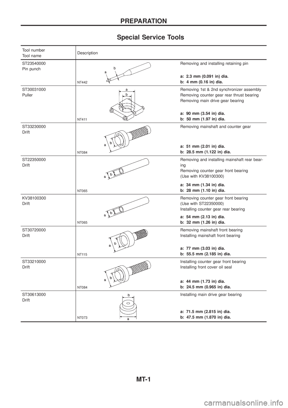
Special Service Tools
Tool number
Tool nameDescription
ST23540000
Pin punch
NT442
Removing and installing retaining pin
a: 2.3 mm (0.091 in) dia.
b: 4 mm (0.16 in) dia.
ST30031000
Puller
NT411
Removing 1st & 2nd synchronizer assembly
Removing counter gear rear thrust bearing
Removing main drive gear bearing
a: 90 mm (3.54 in) dia.
b: 50 mm (1.97 in) dia.
ST33230000
Drift
NT084
Removing mainshaft and counter gear
a: 51 mm (2.01 in) dia.
b: 28.5 mm (1.122 in) dia.
ST22350000
Drift
NT065
Removing and installing mainshaft rear bear-
ing
Removing counter gear front bearing
(Use with KV38100300)
a: 34 mm (1.34 in) dia.
b: 28 mm (1.10 in) dia.
KV38100300
Drift
NT065
Removing counter gear front bearing
(Use with ST22350000)
Installing counter gear rear bearing
a: 54 mm (2.13 in) dia.
b: 32 mm (1.26 in) dia.
ST30720000
Drift
NT115
Removing mainshaft front bearing
Installing mainshaft front bearing
a: 77 mm (3.03 in) dia.
b: 55.5 mm (2.185 in) dia.
ST33210000
Drift
NT084
Installing counter gear front bearing
Installing front cover oil seal
a: 44 mm (1.73 in) dia.
b: 24.5 mm (0.965 in) dia.
ST30613000
Drift
NT073
Installing main drive gear bearing
a: 71.5 mm (2.815 in) dia.
b: 47.5 mm (1.870 in) dia.
PREPARATION
MT-1
Page 1009 of 1226
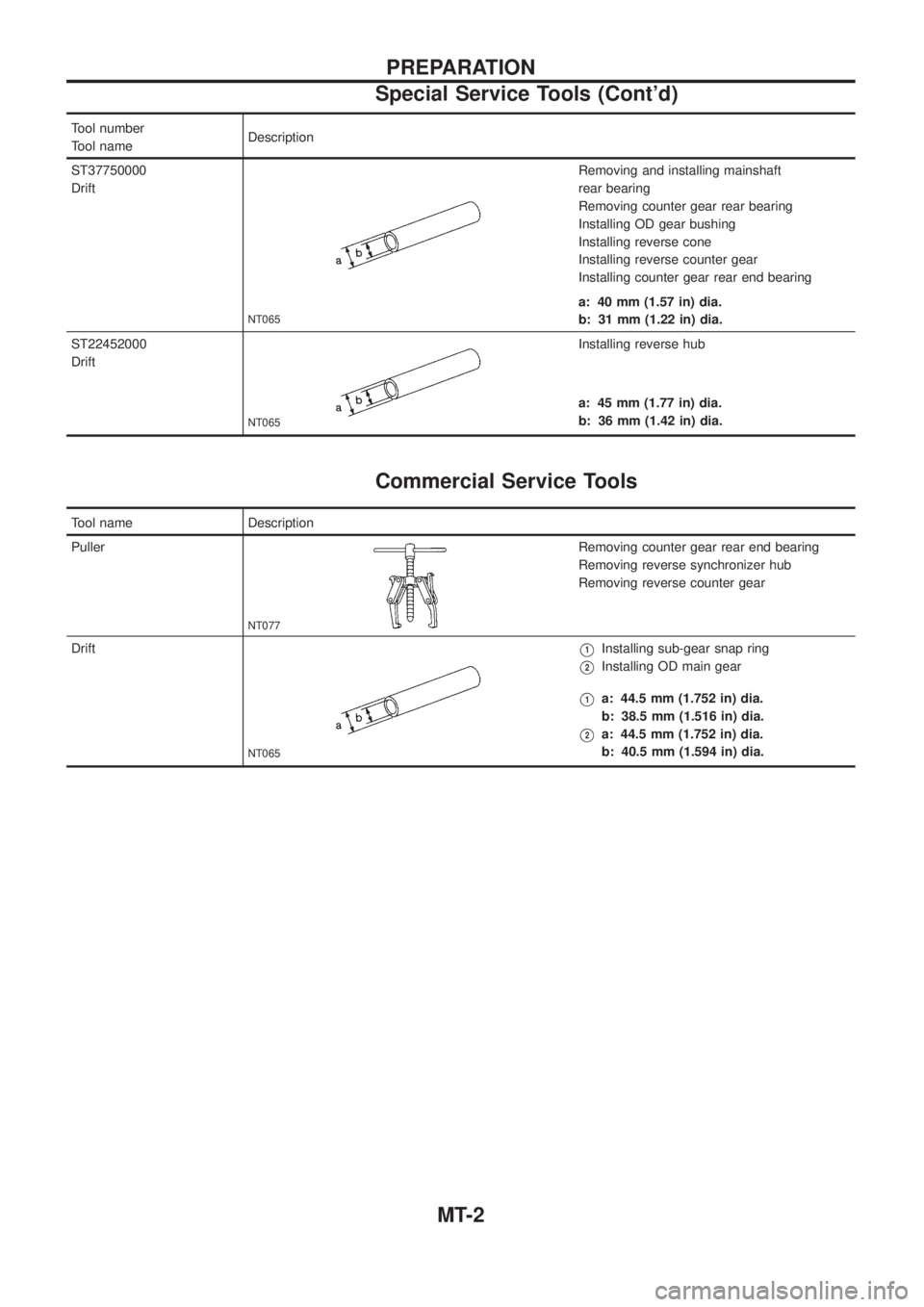
Tool number
Tool nameDescription
ST37750000
Drift
NT065
Removing and installing mainshaft
rear bearing
Removing counter gear rear bearing
Installing OD gear bushing
Installing reverse cone
Installing reverse counter gear
Installing counter gear rear end bearing
a: 40 mm (1.57 in) dia.
b: 31 mm (1.22 in) dia.
ST22452000
Drift
NT065
Installing reverse hub
a: 45 mm (1.77 in) dia.
b: 36 mm (1.42 in) dia.
Commercial Service Tools
Tool name Description
Puller
NT077
Removing counter gear rear end bearing
Removing reverse synchronizer hub
Removing reverse counter gear
Drift
NT065
V1Installing sub-gear snap ring
V2Installing OD main gear
V1a: 44.5 mm (1.752 in) dia.
b: 38.5 mm (1.516 in) dia.
V2a: 44.5 mm (1.752 in) dia.
b: 40.5 mm (1.594 in) dia.
PREPARATION
Special Service Tools (Cont'd)
MT-2
Page 1010 of 1226
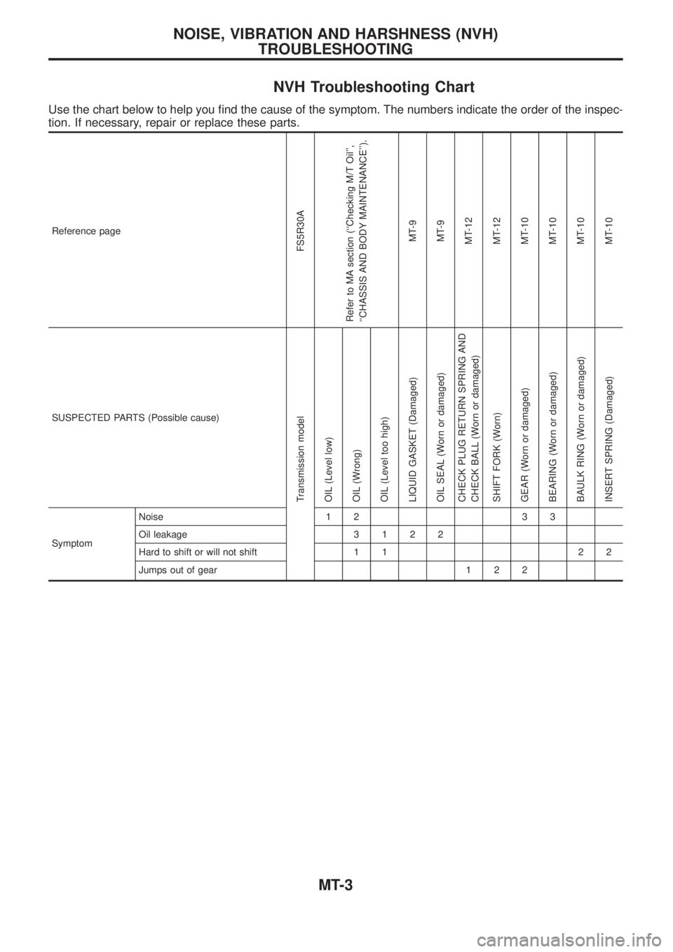
NVH Troubleshooting Chart
Use the chart below to help you ®nd the cause of the symptom. The numbers indicate the order of the inspec-
tion. If necessary, repair or replace these parts.
Reference page
FS5R30A
Refer to MA section (``Checking M/T Oil'',
``CHASSIS AND BODY MAINTENANCE'').
MT-9
MT-9
MT-12
MT-12
MT-10
MT-10
MT-10
MT-10
SUSPECTED PARTS (Possible cause)
Transmission model
OIL (Level low)
OIL (Wrong)
OIL (Level too high)
LIQUID GASKET (Damaged)
OIL SEAL (Worn or damaged)
CHECK PLUG RETURN SPRING AND
CHECK BALL (Worn or damaged)
SHIFT FORK (Worn)
GEAR (Worn or damaged)
BEARING (Worn or damaged)
BAULK RING (Worn or damaged)
INSERT SPRING (Damaged)
SymptomNoise 1 2 3 3
Oil leakage3122
Hard to shift or will not shift 1 1 2 2
Jumps out of gear 1 2 2
NOISE, VIBRATION AND HARSHNESS (NVH)
TROUBLESHOOTING
MT-3