NISSAN PATROL 2006 Manual PDF
Manufacturer: NISSAN, Model Year: 2006, Model line: PATROL, Model: NISSAN PATROL 2006Pages: 1226, PDF Size: 37.18 MB
Page 71 of 1226
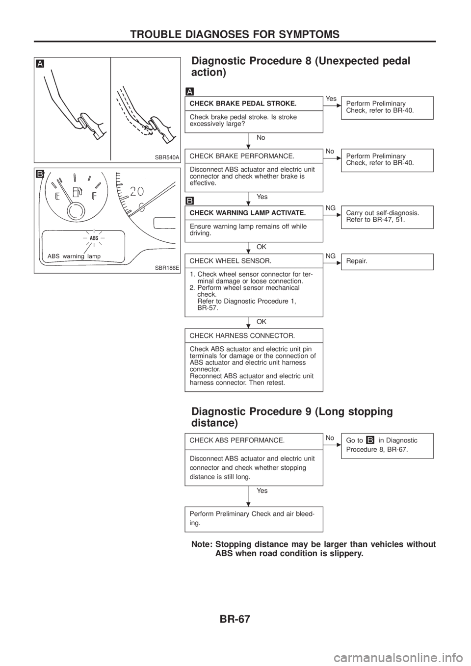
Diagnostic Procedure 8 (Unexpected pedal
action)
CHECK BRAKE PEDAL STROKE.
- ---------------------------------------------------------------------------------------------------------------------------------------------------------------------------------------------------------------------------------------------------------------------------------------------------------------
Check brake pedal stroke. Is stroke
excessively large?
No
cYe s Perform Preliminary
Check, refer to BR-40.
CHECK BRAKE PERFORMANCE.
- ---------------------------------------------------------------------------------------------------------------------------------------------------------------------------------------------------------------------------------------------------------------------------------------------------------------
Disconnect ABS actuator and electric unit
connector and check whether brake is
effective.
Ye s
cNo Perform Preliminary
Check, refer to BR-40.
CHECK WARNING LAMP ACTIVATE.
- ---------------------------------------------------------------------------------------------------------------------------------------------------------------------------------------------------------------------------------------------------------------------------------------------------------------
Ensure warning lamp remains off while
driving.
OK
cNG Carry out self-diagnosis.
Refer to BR-47, 51.
CHECK WHEEL SENSOR.
- ---------------------------------------------------------------------------------------------------------------------------------------------------------------------------------------------------------------------------------------------------------------------------------------------------------------
1. Check wheel sensor connector for ter- minal damage or loose connection.
2. Perform wheel sensor mechanical check.
Refer to Diagnostic Procedure 1,
BR-57.
OK
cNG Repair.
CHECK HARNESS CONNECTOR.
- ---------------------------------------------------------------------------------------------------------------------------------------------------------------------------------------------------------------------------------------------------------------------------------------------------------------
Check ABS actuator and electric unit pin
terminals for damage or the connection of
ABS actuator and electric unit harness
connector.
Reconnect ABS actuator and electric unit
harness connector. Then retest.
Diagnostic Procedure 9 (Long stopping
distance)
CHECK ABS PERFORMANCE.
- ---------------------------------------------------------------------------------------------------------------------------------------------------------------------------------------------------------------------------------------------------------------------------------------------------------------
Disconnect ABS actuator and electric unit
connector and check whether stopping
distance is still long.
Ye s
cNo Go toin Diagnostic
Procedure 8, BR-67.
Perform Preliminary Check and air bleed-
ing.
Note: Stopping distance may be larger than vehicles without ABS when road condition is slippery.
SBR540A
SBR186E
.
.
.
.
.
TROUBLE DIAGNOSES FOR SYMPTOMS
BR-67
Page 72 of 1226
Diagnostic Procedure 10 (ABS does not work.)
CHECK WARNING LAMP ACTIVATE.
- ---------------------------------------------------------------------------------------------------------------------------------------------------------------------------------------------------------------------------------------------------------------------------------------------------------------
Does the ABS warning lamp activate?
No
cYe s Carry out self-diagnosis.
Refer to BR-47, 51.
Go toin Diagnostic Procedure 8,
BR-67.
Note: ABS does not work when vehicle speed is under 10 km/h (6 MPH).
Diagnostic Procedure 11 (Pedal vibration and
noise)
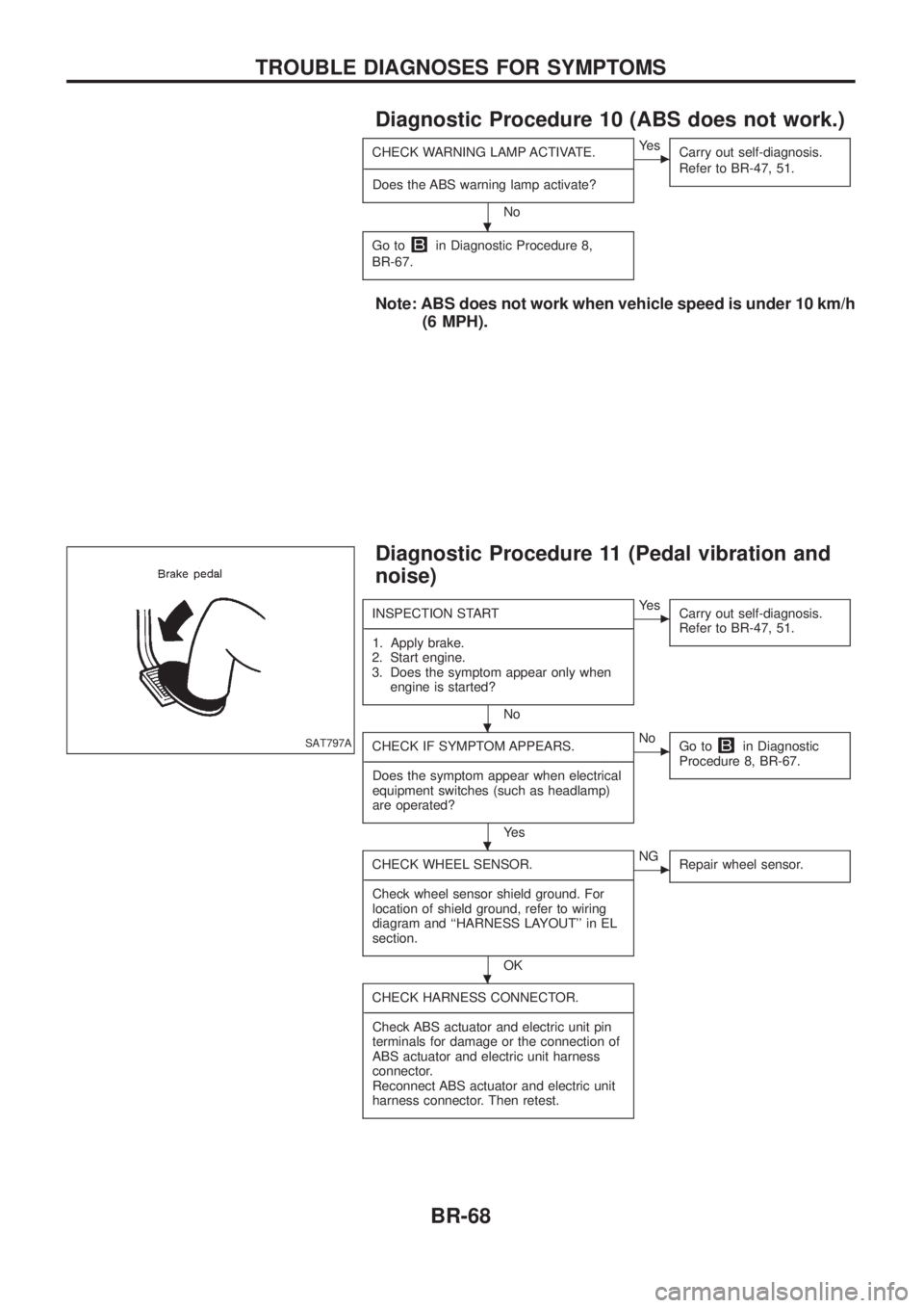
INSPECTION START
- ---------------------------------------------------------------------------------------------------------------------------------------------------------------------------------------------------------------------------------------------------------------------------------------------------------------
1. Apply brake.
2. Start engine.
3. Does the symptom appear only when engine is started?
No
cYe s Carry out self-diagnosis.
Refer to BR-47, 51.
CHECK IF SYMPTOM APPEARS.
- ---------------------------------------------------------------------------------------------------------------------------------------------------------------------------------------------------------------------------------------------------------------------------------------------------------------
Does the symptom appear when electrical
equipment switches (such as headlamp)
are operated?
Ye s
cNo Go toin Diagnostic
Procedure 8, BR-67.
CHECK WHEEL SENSOR.
- ---------------------------------------------------------------------------------------------------------------------------------------------------------------------------------------------------------------------------------------------------------------------------------------------------------------
Check wheel sensor shield ground. For
location of shield ground, refer to wiring
diagram and ``HARNESS LAYOUT'' in EL
section.
OK
cNG Repair wheel sensor.
CHECK HARNESS CONNECTOR.
- ---------------------------------------------------------------------------------------------------------------------------------------------------------------------------------------------------------------------------------------------------------------------------------------------------------------
Check ABS actuator and electric unit pin
terminals for damage or the connection of
ABS actuator and electric unit harness
connector.
Reconnect ABS actuator and electric unit
harness connector. Then retest.
SAT797A
.
.
.
.
TROUBLE DIAGNOSES FOR SYMPTOMS
BR-68
Page 73 of 1226
Note: ABS may operate and cause vibration under any of thefollowing conditions.
+ Applying brake gradually when shifting or operating
clutch.
+ Low friction (slippery) road.
+ High speed cornering.
+ Driving over bumps and pot holes.
+ Engine speed is over 5,000 rpm with vehicle stopped.
Diagnostic Procedure 12 (Warning lamp does
not come on when ignition switch is turned
ON.)
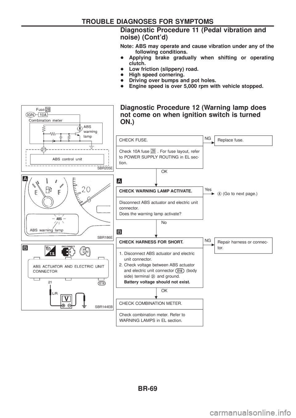
CHECK FUSE.
- ---------------------------------------------------------------------------------------------------------------------------------------------------------------------------------------------------------------------------------------------------------------------------------------------------------------
Check 10A fuse
28. For fuse layout, refer
to POWER SUPPLY ROUTING in EL sec-
tion.
OK
cNG Replace fuse.
CHECK WARNING LAMP ACTIVATE.
- ---------------------------------------------------------------------------------------------------------------------------------------------------------------------------------------------------------------------------------------------------------------------------------------------------------------
Disconnect ABS actuator and electric unit
connector.
Does the warning lamp activate?
No
cYe s jA(Go to next page.)
CHECK HARNESS FOR SHORT.
- ---------------------------------------------------------------------------------------------------------------------------------------------------------------------------------------------------------------------------------------------------------------------------------------------------------------
1. Disconnect ABS actuator and electric unit connector.
2. Check voltage between ABS actuator and electric unit connector
E18(body
side) terminal j
21and ground.
Battery voltage should not exist.
OK
cNG Repair harness or connec-
tor.
CHECK COMBINATION METER.
- ---------------------------------------------------------------------------------------------------------------------------------------------------------------------------------------------------------------------------------------------------------------------------------------------------------------
Check combination meter. Refer to
WARNING LAMPS in EL section.
SBR205E
SBR186E
SBR144EB
.
.
.
TROUBLE DIAGNOSES FOR SYMPTOMS
Diagnostic Procedure 11 (Pedal vibration and
noise) (Cont'd)
BR-69
Page 74 of 1226
jA
CHECK HARNESS CONNECTOR.
- ---------------------------------------------------------------------------------------------------------------------------------------------------------------------------------------------------------------------------------------------------------------------------------------------------------------
Check ABS actuator and electric unit pin
terminals for damage or connection of
ABS actuator and electric unit harness
connector. Reconnect ABS actuator and
electric unit harness connector. Then
retest.
NG
cOK Inspection end
REPLACE.
- ---------------------------------------------------------------------------------------------------------------------------------------------------------------------------------------------------------------------------------------------------------------------------------------------------------------
Replace ABS actuator and electric unit.
.
.
TROUBLE DIAGNOSES FOR SYMPTOMS
Diagnostic Procedure 12 (Warning lamp does
not come on when ignition switch is turned
ON.) (Cont'd)
BR-70
Page 75 of 1226
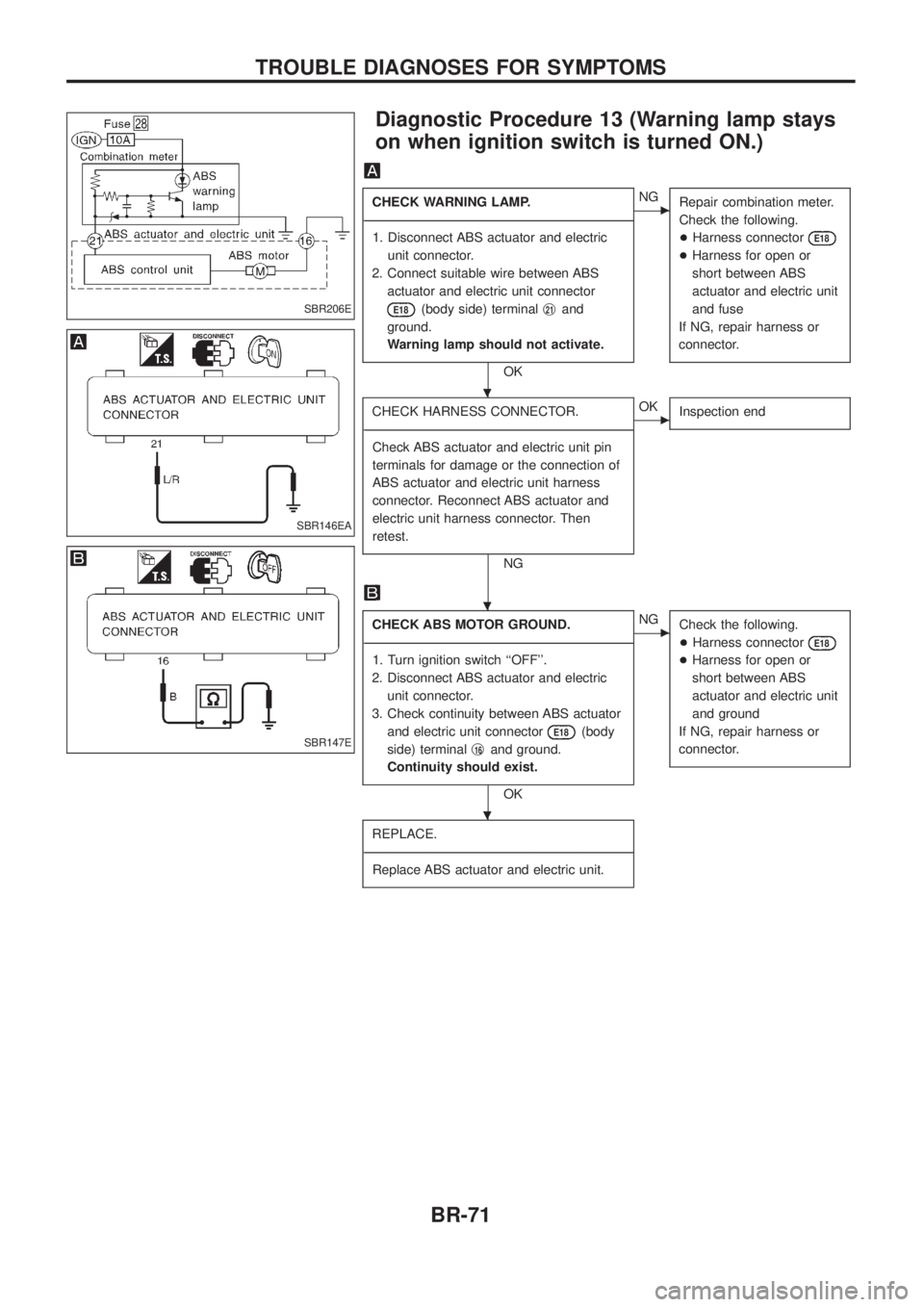
Diagnostic Procedure 13 (Warning lamp stays
on when ignition switch is turned ON.)
CHECK WARNING LAMP.
- ---------------------------------------------------------------------------------------------------------------------------------------------------------------------------------------------------------------------------------------------------------------------------------------------------------------
1. Disconnect ABS actuator and electric unit connector.
2. Connect suitable wire between ABS actuator and electric unit connector
E18(body side) terminal j21and
ground.
Warning lamp should not activate.
OK
cNG Repair combination meter.
Check the following.
+Harness connector
E18
+Harness for open or
short between ABS
actuator and electric unit
and fuse
If NG, repair harness or
connector.
CHECK HARNESS CONNECTOR.
- ---------------------------------------------------------------------------------------------------------------------------------------------------------------------------------------------------------------------------------------------------------------------------------------------------------------
Check ABS actuator and electric unit pin
terminals for damage or the connection of
ABS actuator and electric unit harness
connector. Reconnect ABS actuator and
electric unit harness connector. Then
retest.
NG
cOK Inspection end
CHECK ABS MOTOR GROUND.
- ---------------------------------------------------------------------------------------------------------------------------------------------------------------------------------------------------------------------------------------------------------------------------------------------------------------
1. Turn ignition switch ``OFF''.
2. Disconnect ABS actuator and electric unit connector.
3. Check continuity between ABS actuator and electric unit connector
E18(body
side) terminal j
16and ground.
Continuity should exist.
OK
cNG Check the following.
+Harness connector
E18
+Harness for open or
short between ABS
actuator and electric unit
and ground
If NG, repair harness or
connector.
REPLACE.
- ---------------------------------------------------------------------------------------------------------------------------------------------------------------------------------------------------------------------------------------------------------------------------------------------------------------
Replace ABS actuator and electric unit.
SBR206E
SBR146EA
SBR147E
.
.
.
TROUBLE DIAGNOSES FOR SYMPTOMS
BR-71
Page 76 of 1226
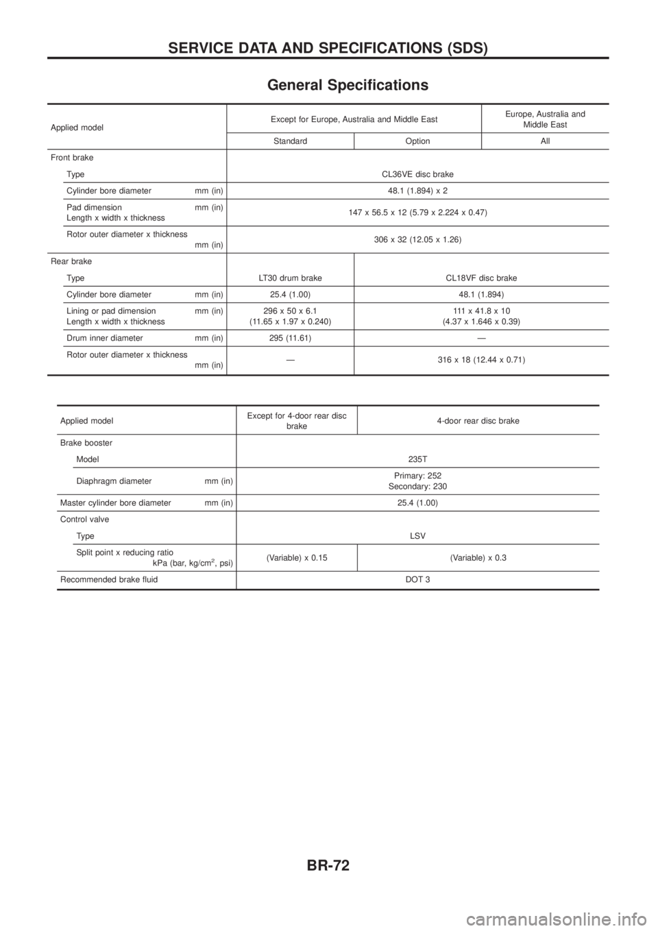
General Speci®cations
Applied modelExcept for Europe, Australia and Middle East
Europe, Australia and
Middle East
Standard Option All
Front brake Type CL36VE disc brake
Cylinder bore diameter mm (in) 48.1 (1.894) x 2
Pad dimension mm (in)
Length x width x thickness 147 x 56.5 x 12 (5.79 x 2.224 x 0.47)
Rotor outer diameter x thickness mm (in) 306 x 32 (12.05 x 1.26)
Rear brake Type LT30 drum brake CL18VF disc brake
Cylinder bore diameter mm (in) 25.4 (1.00) 48.1 (1.894)
Lining or pad dimension mm (in)
Length x width x thickness 296x50x6.1
(11.65 x 1.97 x 0.240) 111x41.8x10
(4.37 x 1.646 x 0.39)
Drum inner diameter mm (in) 295 (11.61) Ð
Rotor outer diameter x thickness mm (in)Ð 316 x 18 (12.44 x 0.71)
Applied model Except for 4-door rear disc
brake 4-door rear disc brake
Brake booster Model 235T
Diaphragm diameter mm (in) Primary: 252
Secondary: 230
Master cylinder bore diameter mm (in) 25.4 (1.00)
Control valve Type LSV
Split point x reducing ratio kPa (bar, kg/cm
2, psi)(Variable) x 0.15 (Variable) x 0.3
Recommended brake ¯uid DOT 3
SERVICE DATA AND SPECIFICATIONS (SDS)
BR-72
Page 77 of 1226
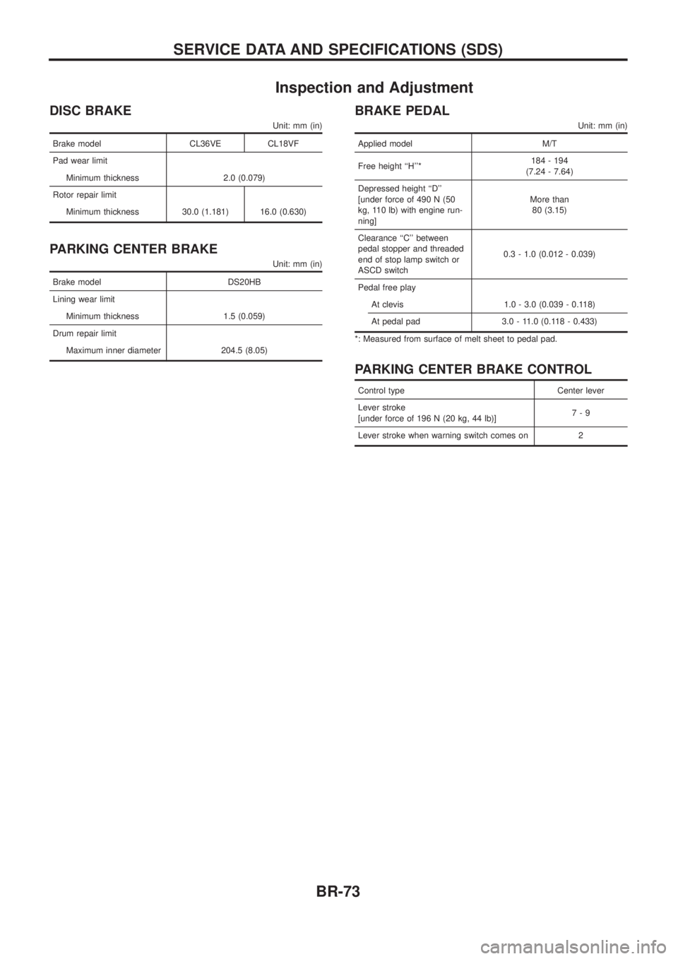
Inspection and Adjustment
DISC BRAKE
Unit: mm (in)
Brake model CL36VE CL18VF
Pad wear limit
Minimum thickness 2.0 (0.079)
Rotor repair limit
Minimum thickness 30.0 (1.181) 16.0 (0.630)
PARKING CENTER BRAKE
Unit: mm (in)
Brake model DS20HB
Lining wear limit
Minimum thickness 1.5 (0.059)
Drum repair limit
Maximum inner diameter 204.5 (8.05)
BRAKE PEDAL
Unit: mm (in)
Applied model M/T
Free height ``H''*184 - 194
(7.24 - 7.64)
Depressed height ``D''
[under force of 490 N (50
kg, 110 lb) with engine run-
ning]More than
80 (3.15)
Clearance ``C'' between
pedal stopper and threaded
end of stop lamp switch or
ASCD switch0.3 - 1.0 (0.012 - 0.039)
Pedal free play
At clevis 1.0 - 3.0 (0.039 - 0.118)
At pedal pad 3.0 - 11.0 (0.118 - 0.433)
*: Measured from surface of melt sheet to pedal pad.
PARKING CENTER BRAKE CONTROL
Control type Center lever
Lever stroke
[under force of 196 N (20 kg, 44 lb)]7-9
Lever stroke when warning switch comes on 2
SERVICE DATA AND SPECIFICATIONS (SDS)
BR-73
Page 78 of 1226
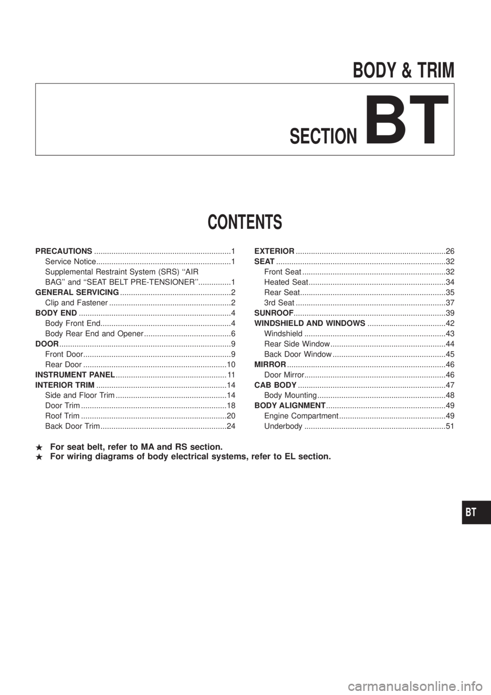
BODY & TRIM
SECTION
BT
CONTENTS
PRECAUTIONS ...............................................................1
Service Notice..............................................................1
Supplemental Restraint System (SRS) ``AIR
BAG''and``SEATBELTPRE-TENSIONER''...............1
GENERAL SERVICING ...................................................2
Clip and Fastener ........................................................2
BODY END ......................................................................4
Body Front End............................................................4
Body Rear End and Opener ........................................6
DOOR ........................................................................\
.......9
Front Door....................................................................9
Rear Door ..................................................................10
INSTRUMENT PANEL ................................................... 11
INTERIOR TRIM ............................................................14
Side and Floor Trim ...................................................14
Door Trim ...................................................................18
Roof Trim ...................................................................20
Back Door Trim ..........................................................24 EXTERIOR
.....................................................................26
SEAT ........................................................................\
......32
Front Seat ..................................................................32
Heated Seat ...............................................................34
Rear Seat...................................................................35
3rd Seat .....................................................................37
SUNROOF ......................................................................39
WINDSHIELD AND WINDOWS ....................................42
Windshield .................................................................43
Rear Side Window .....................................................44
Back Door Window ....................................................45
MIRROR ........................................................................\
.46
Door Mirror.................................................................46
CAB BODY ....................................................................47
Body Mounting ...........................................................48
BODY ALIGNMENT .......................................................49
Engine Compartment .................................................49
Underbody .................................................................51
. For seat belt, refer to MA and RS section.
. For wiring diagrams of body electrical systems, refer to EL section.
BT
Page 79 of 1226
Service Notice
+When removing or installing various parts, place a cloth or padding onto the vehicle body to prevent
scratches.
+Handle trim, molding, instruments, grille, etc. carefully during removing or installing. Be careful not to soil
or damage them.
+Apply sealing compound where necessary when installing parts.
+When applying sealing compound, be careful that the sealing compound does not protrude from parts.
+When replacing any metal parts (for example body outer panel, members, etc.), be sure to take rust pre-
vention measures.
Supplemental Restraint System (SRS) ``AIR
BAG'' and ``SEAT BELT PRE-TENSIONER''
The Supplemental Restraint System such as ``AIR BAG'' and ``SEAT BELT PRE-TENSIONER'' used along with
a seat belt, helps to reduce the risk or severity of injury to the driver and front passenger in a frontal collision.
The SRS system composition which is available to NISSAN MODEL Y61 is as follows (The composition var-
ies according to the destination.):
Driver air bag module (located in the center of the steering wheel), front passenger air bag module (located
on the instrument panel on passenger side), seat belt pre-tensioner, a diagnosis sensor unit, warning lamp,
wiring harness and spiral cable.
Information necessary to service the system safely is included in theRS sectionof this Service Manual.
WARNING:
+To avoid rendering the SRS inoperative, which could increase the risk of personal injury or death
in the event of a collision which would result in air bag in¯ation, all maintenance must be performed
by an authorized NISSAN dealer.
+Improper maintenance, including incorrect removal and installation of the SRS, can lead to per-
sonal injury caused by unintentional activation of the system. For removal of Spiral Cable and Air
Bag Module, see the RS section.
+Do not use electrical test equipment on any circuit related to the SRS unless instructed to in this
Service Manual. Spiral cable and wiring harnesses covered with yellow insulation either just before
the harness connectors or for the complete harness are related to the SRS.
PRECAUTIONS
BT-1
Page 80 of 1226
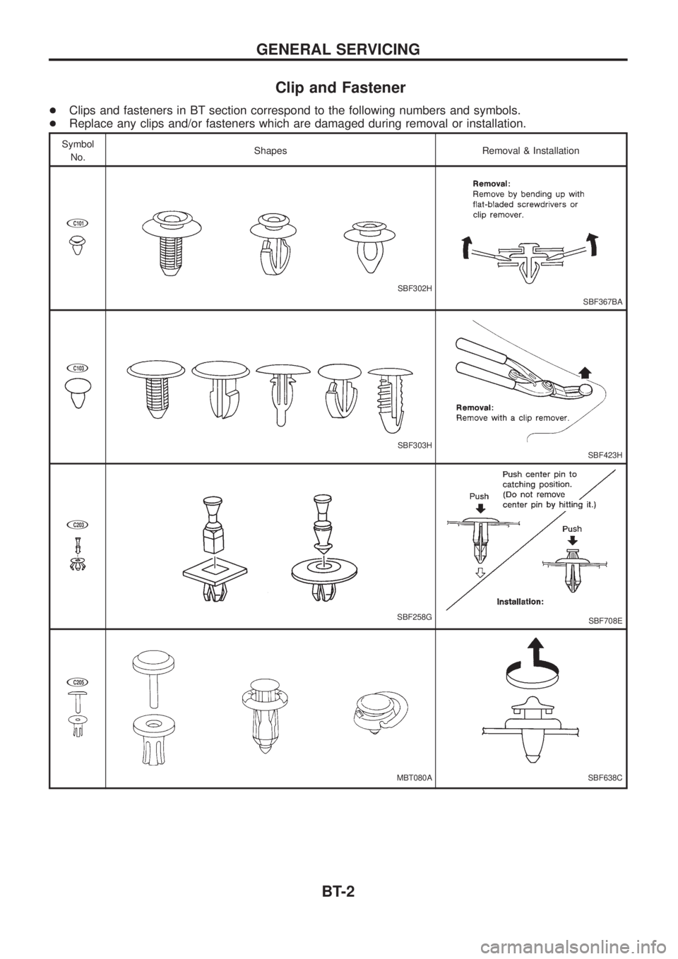
Clip and Fastener
+Clips and fasteners in BT section correspond to the following numbers and symbols.
+Replace any clips and/or fasteners which are damaged during removal or installation.
Symbol
No.Shapes Removal & Installation
jC101
SBF302H
SBF367BA
jC103
SBF303HSBF423H
jC203
SBF258GSBF708E
jC205
MBT080ASBF638C
GENERAL SERVICING
BT-2