NISSAN PATROL 2006 Manual Online
PATROL 2006
NISSAN
NISSAN
https://www.carmanualsonline.info/img/5/57368/w960_57368-0.png
NISSAN PATROL 2006 Manual Online
Trending: stop start, trunk release, remote start, main tank, door lock, fog light bulb, tire size
Page 81 of 1226
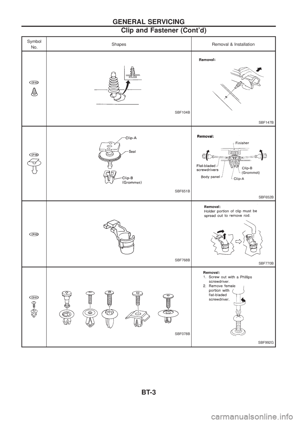
Symbol
No.Shapes Removal & Installation
jCE103
SBF104B
SBF147B
jCF109
SBF651B
SBF652B
jCR103
SBF768BSBF770B
jCS101
SBF078B
SBF992G
GENERAL SERVICING
Clip and Fastener (Cont'd)
BT-3
Page 82 of 1226
Body Front End
+When removing or installing hood, place a cloth or other padding on front fender panel and cowl top. This
prevents vehicle body from being scratched.
+Bumper fascia is made of plastic. Do not use excessive force and be sure to keep oil away from it.
+Hood adjustment: Adjust at hinge portion.
+Hood lock adjustment: After adjusting, check hood lock control operation. Apply a coat of grease to hood
locks engaging mechanism.
+Hood opener: Do not attempt to bend cable forcibly. Doing so increases effort required to unlock hood.
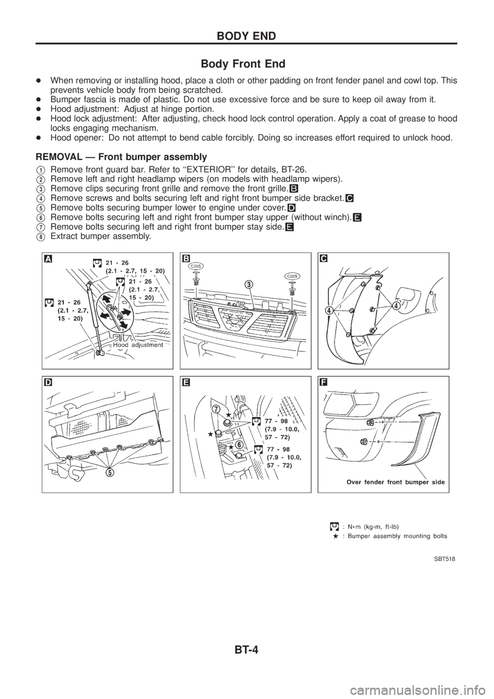
REMOVAL Ð Front bumper assembly
V1Remove front guard bar. Refer to ``EXTERIOR'' for details, BT-26.
V2Remove left and right headlamp wipers (on models with headlamp wipers).
V3Remove clips securing front grille and remove the front grille.
V4Remove screws and bolts securing left and right front bumper side bracket.
V5Remove bolts securing bumper lower to engine under cover.
V6Remove bolts securing left and right front bumper stay upper (without winch).
V7Remove bolts securing left and right front bumper stay side.
V8Extract bumper assembly.
SBT518
BODY END
BT-4
Page 83 of 1226
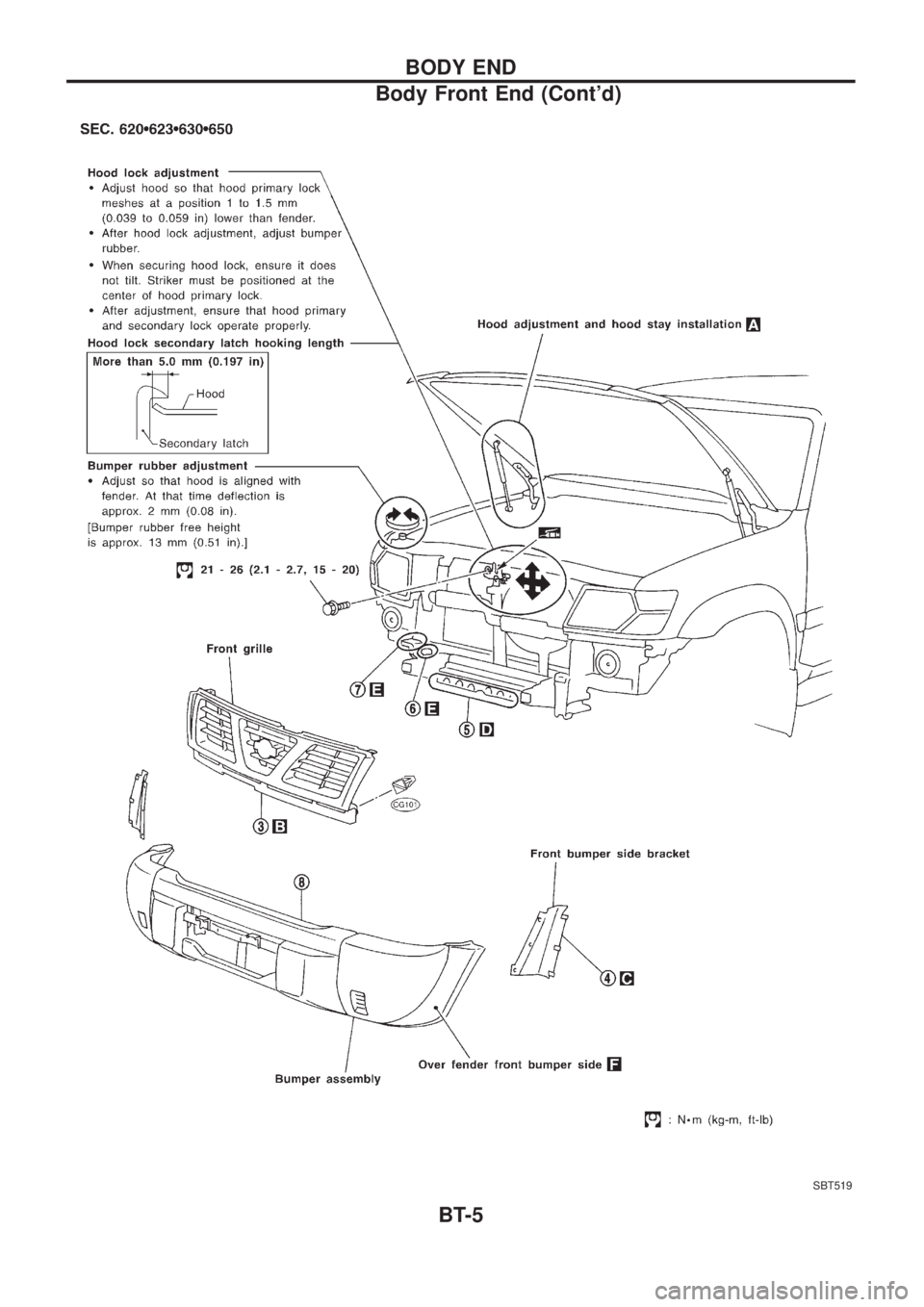
SBT519
BODY END
Body Front End (Cont'd)
BT-5
Page 84 of 1226
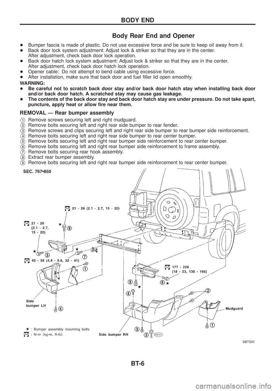
Body Rear End and Opener
+Bumper fascia is made of plastic. Do not use excessive force and be sure to keep oil away from it.
+Back door lock system adjustment: Adjust lock & striker so that they are in the center.
After adjustment, check back door lock operation.
+Back door hatch lock system adjustment: Adjust lock & striker so that they are in the center.
After adjustment, check back door hatch lock operation.
+Opener cable: Do not attempt to bend cable using excessive force.
+After installation, make sure that back door and fuel ®ller lid open smoothly.
WARNING:
+Be careful not to scratch back door stay and/or back door hatch stay when installing back door
and/or back door hatch. A scratched stay may cause gas leakage.
+The contents of the back door stay and back door hatch stay are under pressure. Do not take apart,
puncture, apply heat or allow ®re near them.
REMOVAL Ð Rear bumper assembly
V1Remove screws securing left and right mudguard.
V2Remove bolts securing left and right rear side bumper to rear fender.
V3Remove screws and clips securing left and right rear side bumper to rear bumper side reinforcement.
V4Remove bolts securing left and right rear side bumper to rear center bumper.
V5Remove bolts securing left and right rear bumper side reinforcement to rear center bumper.
V6Remove bolts securing left and right rear bumper side reinforcement to frame assembly.
V7Remove bolts securing rear hook assembly.
V8Extract rear bumper assembly.
V9Remove bolts securing left and right rear bumper side reinforcement to rear center bumper.
SBT520
BODY END
BT-6
Page 85 of 1226
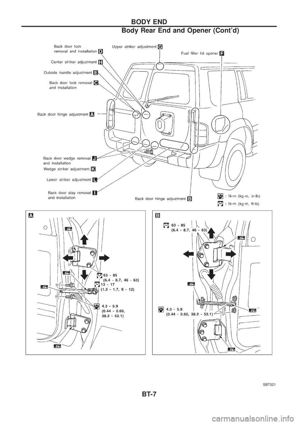
SBT521
BODY END
Body Rear End and Opener (Cont'd)
BT-7
Page 86 of 1226
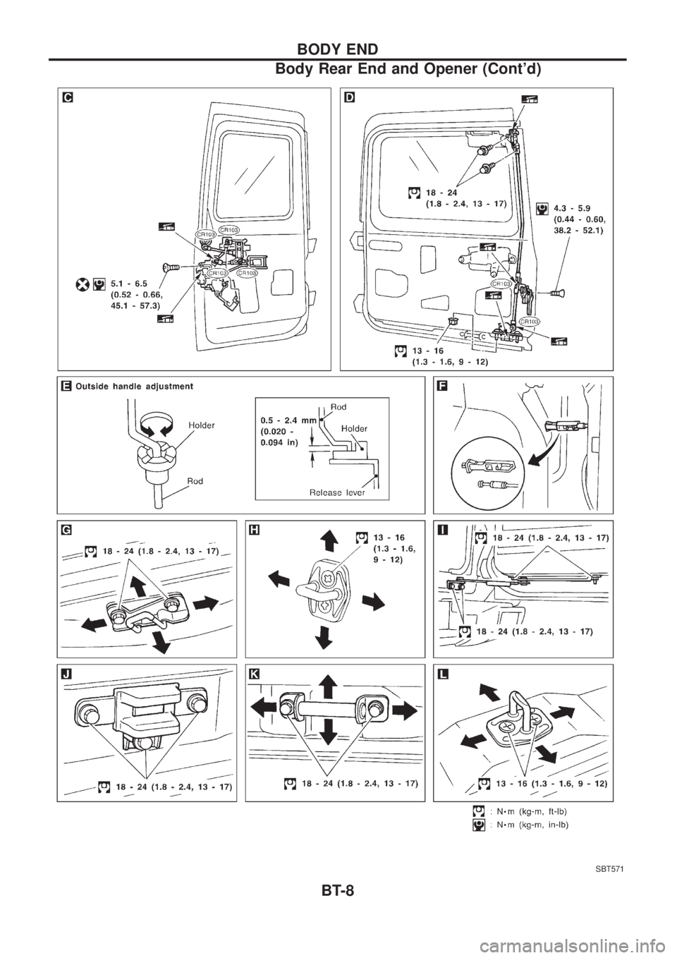
SBT571
BODY END
Body Rear End and Opener (Cont'd)
BT-8
Page 87 of 1226
Front Door
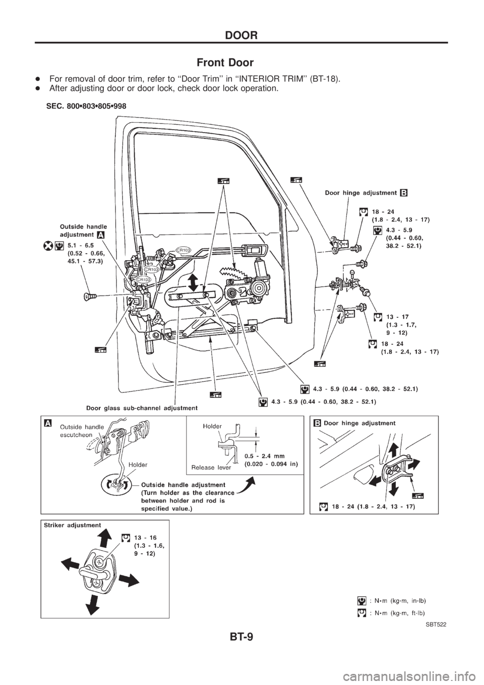
+For removal of door trim, refer to ``Door Trim'' in ``INTERIOR TRIM'' (BT-18).
+After adjusting door or door lock, check door lock operation.
SBT522
DOOR
BT-9
Page 88 of 1226
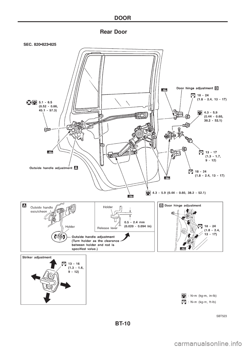
Rear Door
SBT523
DOOR
BT-10
Page 89 of 1226
CAUTION:
+Disconnect both battery cables in advance.
+Disconnect air bag system line in advance.
+Never tamper with or force air bag lid open, as this may adversely affect air bag performance.
+Be careful not to scratch pad and other parts.
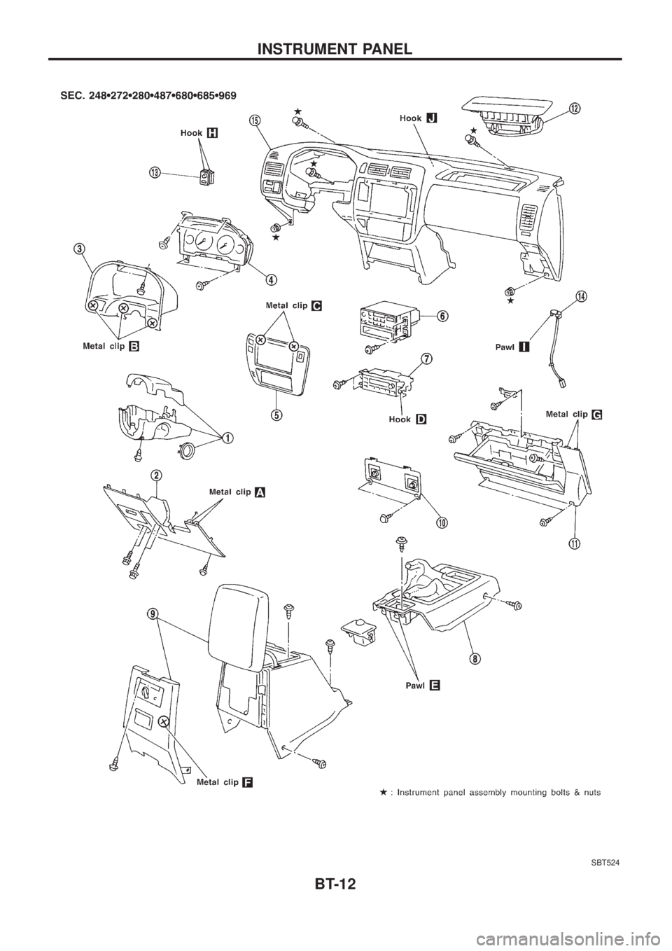
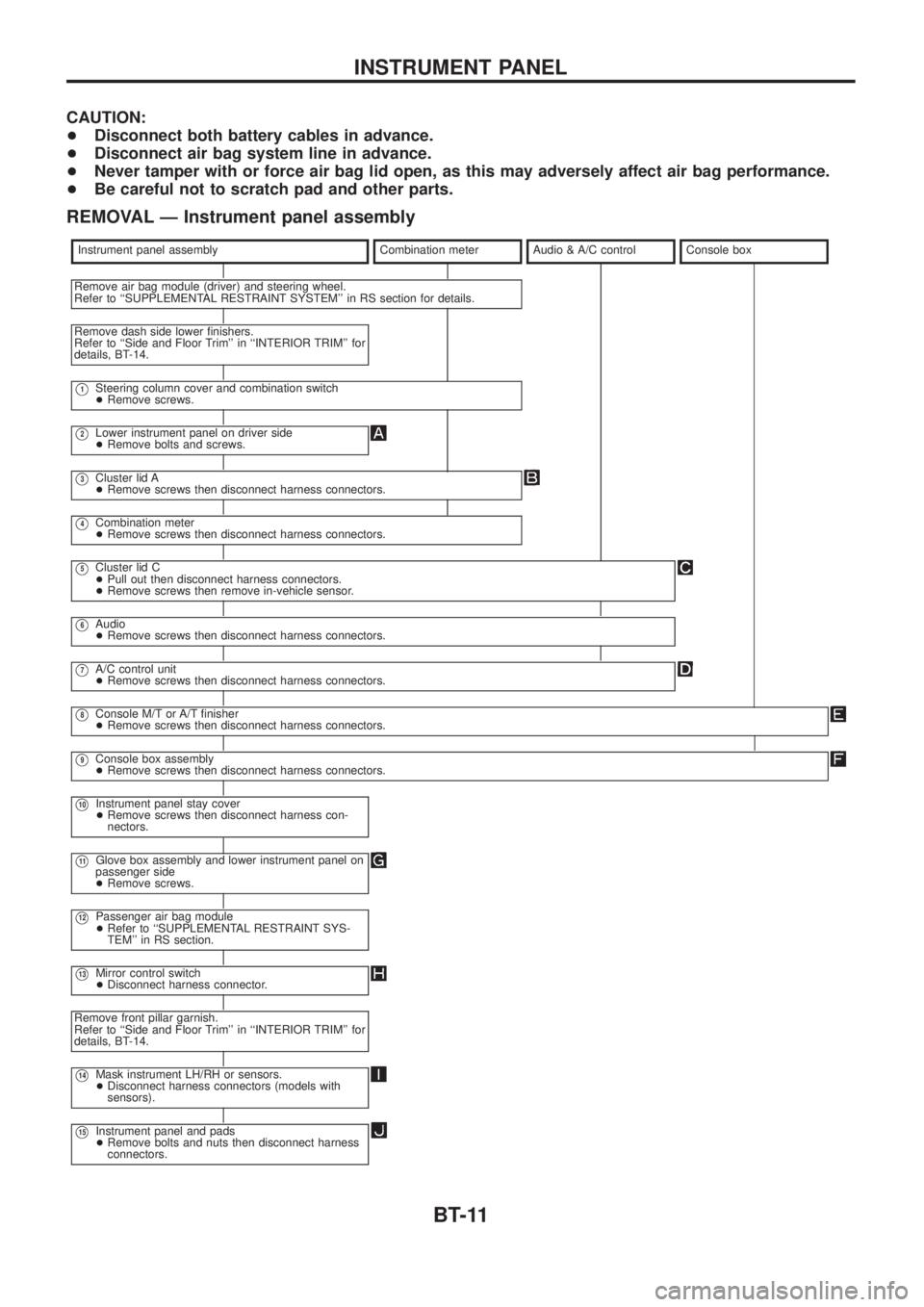
REMOVAL Ð Instrument panel assembly
Instrument panel assemblyCombination meterAudio & A/C controlConsole box
Remove air bag module (driver) and steering wheel.
Refer to ``SUPPLEMENTAL RESTRAINT SYSTEM'' in RS section for details.
Remove dash side lower ®nishers.
Refer to ``Side and Floor Trim'' in ``INTERIOR TRIM'' for
details, BT-14.
V1Steering column cover and combination switch
+Remove screws.
V2Lower instrument panel on driver side
+Remove bolts and screws.
V3Cluster lid A
+Remove screws then disconnect harness connectors.
V4Combination meter
+Remove screws then disconnect harness connectors.
V5Cluster lid C
+Pull out then disconnect harness connectors.
+Remove screws then remove in-vehicle sensor.
V6Audio
+Remove screws then disconnect harness connectors.
V7A/C control unit
+Remove screws then disconnect harness connectors.
V8Console M/T or A/T ®nisher
+Remove screws then disconnect harness connectors.
V9Console box assembly
+Remove screws then disconnect harness connectors.
V10Instrument panel stay cover
+Remove screws then disconnect harness con-
nectors.
V11Glove box assembly and lower instrument panel on
passenger side
+Remove screws.
V12Passenger air bag module
+Refer to ``SUPPLEMENTAL RESTRAINT SYS-
TEM'' in RS section.
V13Mirror control switch
+Disconnect harness connector.
Remove front pillar garnish.
Refer to ``Side and Floor Trim'' in ``INTERIOR TRIM'' for
details, BT-14.
V14Mask instrument LH/RH or sensors.
+Disconnect harness connectors (models with
sensors).
V15Instrument panel and pads
+Remove bolts and nuts then disconnect harness
connectors.
INSTRUMENT PANEL
BT-11
Page 90 of 1226
SBT524
INSTRUMENT PANEL
BT-12
Trending: height, diagram, speaker, Tail, dimensions, window, overheating
