water pump NISSAN PICK-UP 1998 User Guide
[x] Cancel search | Manufacturer: NISSAN, Model Year: 1998, Model line: PICK-UP, Model: NISSAN PICK-UP 1998Pages: 1659, PDF Size: 53.39 MB
Page 808 of 1659
lAfter disconnecting vacuum or air hoses, attach a tag to
indicate the proper connection.
lUse only the fluids and lubricants specified in this manual.
lUse approved bonding agent, sealants or their equivalents
when required.
lUse tools and recommended special tools where specified
for safe and efficient service repairs.
lWhen repairing the fuel, oil, water, vacuum or exhaust
systems, check all affected lines for leaks.
lDispose of drained oil or the solvent used for cleaning parts
in an appropriate manner.
WARNING:
To prevent ECM from storing the diagnostic trouble codes,
do not carelessly disconnect the harness connectors which
are related to the ECCS system and TCM (Transmission
Control Module) system. The connectors should be discon-
nected only when working according to the WORK FLOW of
TROUBLE DIAGNOSES in EC section.
Precautions for Multiport Fuel Injection
System or ECCS Engine
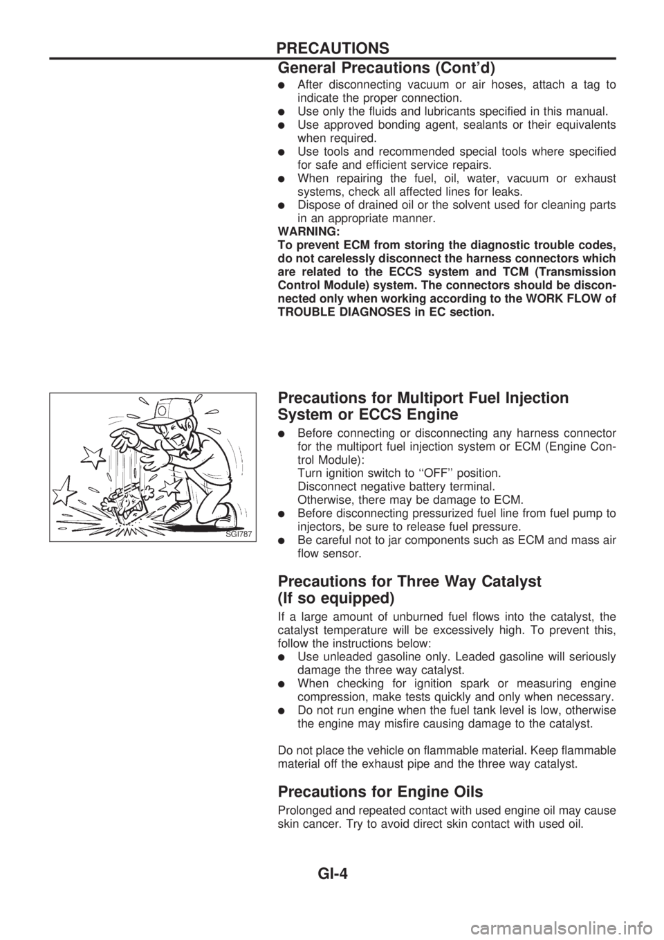
lBefore connecting or disconnecting any harness connector
for the multiport fuel injection system or ECM (Engine Con-
trol Module):
Turn ignition switch to ``OFF'' position.
Disconnect negative battery terminal.
Otherwise, there may be damage to ECM.
lBefore disconnecting pressurized fuel line from fuel pump to
injectors, be sure to release fuel pressure.
lBe careful not to jar components such as ECM and mass air
flow sensor.
Precautions for Three Way Catalyst
(If so equipped)
If a large amount of unburned fuel flows into the catalyst, the
catalyst temperature will be excessively high. To prevent this,
follow the instructions below:
lUse unleaded gasoline only. Leaded gasoline will seriously
damage the three way catalyst.
lWhen checking for ignition spark or measuring engine
compression, make tests quickly and only when necessary.
lDo not run engine when the fuel tank level is low, otherwise
the engine may misfire causing damage to the catalyst.
Do not place the vehicle on flammable material. Keep flammable
material off the exhaust pipe and the three way catalyst.
Precautions for Engine Oils
Prolonged and repeated contact with used engine oil may cause
skin cancer. Try to avoid direct skin contact with used oil.
SGI787
PRECAUTIONS
General Precautions (Cont'd)
GI-4
Page 870 of 1659
Throttle body ................................................. EM-9
Throttle position sensor (TPS)................... EC-113
Throwout bearing - See Clutch release
bearing........................................................ CL-9
Tie-rod .......................................................... ST-37
Tie-rod ball joints.......................................... ST-37
Tightening torque of standard bolts .............. GI-54
Timing chain ................................................ EM-13
Timing gear ................................................. EM-89
Tire rotation ................................................. MA-35
Tire size ........................................................ GI-46
Tooth contact (R180A) ................................ PD-26
Tooth contact (C200) ................................... PD-49
Tooth contact (H233B) ................................ PD-70
Torsion bar spring ........................................ FA-28
Tow truck towing ........................................... GI-51
Towing point.................................................. GI-53
Transfer case ................................................. TF-8
Transfer oil replacement ............................. MA-33
Transfer serial number.................................. GI-43
Transmission case (M/T) (FS5R30A).......... MT-35
Transmission case (M/T) (FS5W71C)......... MT-14
Transmission serial number.......................... GI-43
Tread - FR&RR (Dimensions) ...................... GI-44
Trim .............................................................. BT-15
Triple pressure switch ........................... HA-12, 44
Turn signal lamp........................................... EL-74
Two-pole lift................................................... GI-50
U
Under body ....................................................BT-46
Upper link (front susp.) ................................ FA-31
V
VSS - Wiring diagram .................................EC-119
Vacuum hose (brake system) .......................BR-17
Vacuum hose drawing (ECCS).....................EC-12
Vacuum pump ...............................................BR-19
Valve clearance adjustment .........................MA-23
Valve clearance ............................................EM-31
Valve guide (KA24 engine) ......................... EM-29Valve guide (TD25 engine) ..........................EM-56
Valve lifter .....................................................EM-60
Valve seat (KA24 engine) ............................EM-31
Valve seat (TD25 engine) ............................EM-57
Valve spring (KA24 engine) .........................EM-32
Valve spring (TD25 engine) .........................EM-60
Vehicle identification number .........................GI-40
Vehicle recovery (freeing a stuck
vehicle) .......................................................GI-53
Vehicle speed sensor (VSS).......................EC-118
Ventilator door control rod adjustment .........HA-45
Viscosity number (SAE) ...............................MA-13
W
WARN - Wiring diagram ..............................EL-106
WINDOW - Wiring diagram ........................ EL-157
WIPER - Wiring diagram ............................ EL-122
Warning lamps ........................................... EL-105
Washer, front .............................................. EL-120
Water cock control rod adjustment.............. HA-46
Water pump (KA24 engine) ........................... LC-7
Water pump (TD25 engine) ......................... LC-21
Weatherstrip - See Exterior ......................... BT-24
Wheel alignment (front).................................. FA-7
Wheel balance............................................. MA-34
Wheel bearing (front axle) ............................. FA-5
Wheel bearing (rear)...................................... RA-4
Wheel hub (front) ......................................... FA-16
Wheel sensors (ABS) .................................. BR-35
Wheel size .................................................... GI-46
Wheelbase (Dimensions) .............................. GI-44
Width (Dimensions)....................................... GI-44
Window, back ............................................... BT-24
Window, door ............................................... BT-10
Window, side ................................................ BT-38
Windshield .................................................... BT-36
Wiper, front ................................................. EL-120
Wiring diagram (cell code) list.................... EL-253
Wiring diagrams .............................................. GI-9
Withdrawal lever (clutch)................................ CL-9
Wrist pin - See Piston pin inspection .......... EM-39
ALPHABETICAL INDEX
IDX-8
Page 939 of 1659
ENGINE LUBRICATION &
COOLING SYSTEMS
SECTION
LC
CONTENTS
PRECAUTIONS AND PREPARATION..................... 1
Liquid Gasket Application Procedure .................... 1
Special Service Tools ............................................ 2
KA
ENGINE LUBRICATION SYSTEM............................ 3
Lubrication Circuit .................................................. 3
Oil Pressure Check ................................................ 4
Oil Pump ................................................................ 4
ENGINE COOLING SYSTEM.................................... 6
Cooling Circuit........................................................ 6
System Check ........................................................ 6
Water Pump ........................................................... 7
Thermostat ............................................................. 8
Radiator.................................................................. 9
Cooling Fan (Crankshaft driven).......................... 10
TD
ENGINE LUBRICATION SYSTEM.......................... 12
Lubrication Circuit ................................................ 12
Oil Pressure Check (On-vehicle service) ............ 13
Oil Pump .............................................................. 14
Oil Filter Bracket .................................................. 16
Oil Cooler ............................................................. 17Oil Jet ................................................................... 18
ENGINE COOLING SYSTEM.................................. 19
Cooling Circuit...................................................... 19
Cooling System Inspection .................................. 20
Water Pump and Cooling Fan (Camshaft
driven) .................................................................. 21
Thermostat ........................................................... 23
Radiator................................................................ 24
Refilling Engine Coolant ...................................... 24
ENGINE ROOM FAN MOTOR ELECTRICAL
CIRCUIT................................................................... 25
Wiring Diagram .................................................... 25
Cooling Fan (Motor driven) .................................. 26
Electrical Components Inspection ....................... 26
ENGINE COOLING SYSTEM.................................. 28
Radiator (Aluminum type) .................................... 28
Overheating Cause Analysis ............................... 31
SERVICE DATA AND SPECIFICATIONS (SDS)... 32
Engine Lubrication System (KA).......................... 32
Engine Cooling System (KA) ............................... 32
Engine Lubrication System (TD).......................... 32
Engine Cooling System (TD) ............................... 32
LC
Page 946 of 1659
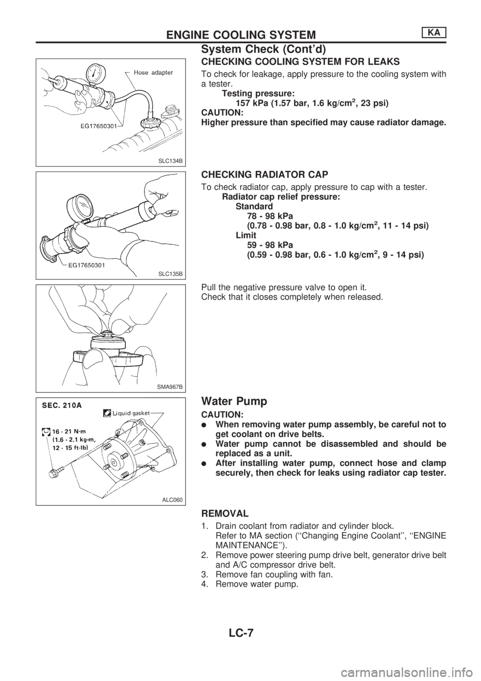
CHECKING COOLING SYSTEM FOR LEAKS
To check for leakage, apply pressure to the cooling system with
a tester.
Testing pressure:
157 kPa (1.57 bar, 1.6 kg/cm
2, 23 psi)
CAUTION:
Higher pressure than specified may cause radiator damage.
CHECKING RADIATOR CAP
To check radiator cap, apply pressure to cap with a tester.
Radiator cap relief pressure:
Standard
78-98kPa
(0.78 - 0.98 bar, 0.8 - 1.0 kg/cm
2, 11 - 14 psi)
Limit
59-98kPa
(0.59 - 0.98 bar, 0.6 - 1.0 kg/cm
2,9-14psi)
Pull the negative pressure valve to open it.
Check that it closes completely when released.
Water Pump
CAUTION:
lWhen removing water pump assembly, be careful not to
get coolant on drive belts.
lWater pump cannot be disassembled and should be
replaced as a unit.
lAfter installing water pump, connect hose and clamp
securely, then check for leaks using radiator cap tester.
REMOVAL
1. Drain coolant from radiator and cylinder block.
Refer to MA section (``Changing Engine Coolant'', ``ENGINE
MAINTENANCE'').
2. Remove power steering pump drive belt, generator drive belt
and A/C compressor drive belt.
3. Remove fan coupling with fan.
4. Remove water pump.
SLC134B
SLC135B
SMA967B
ALC060
ENGINE COOLING SYSTEMKA
System Check (Cont'd)
LC-7
Page 947 of 1659
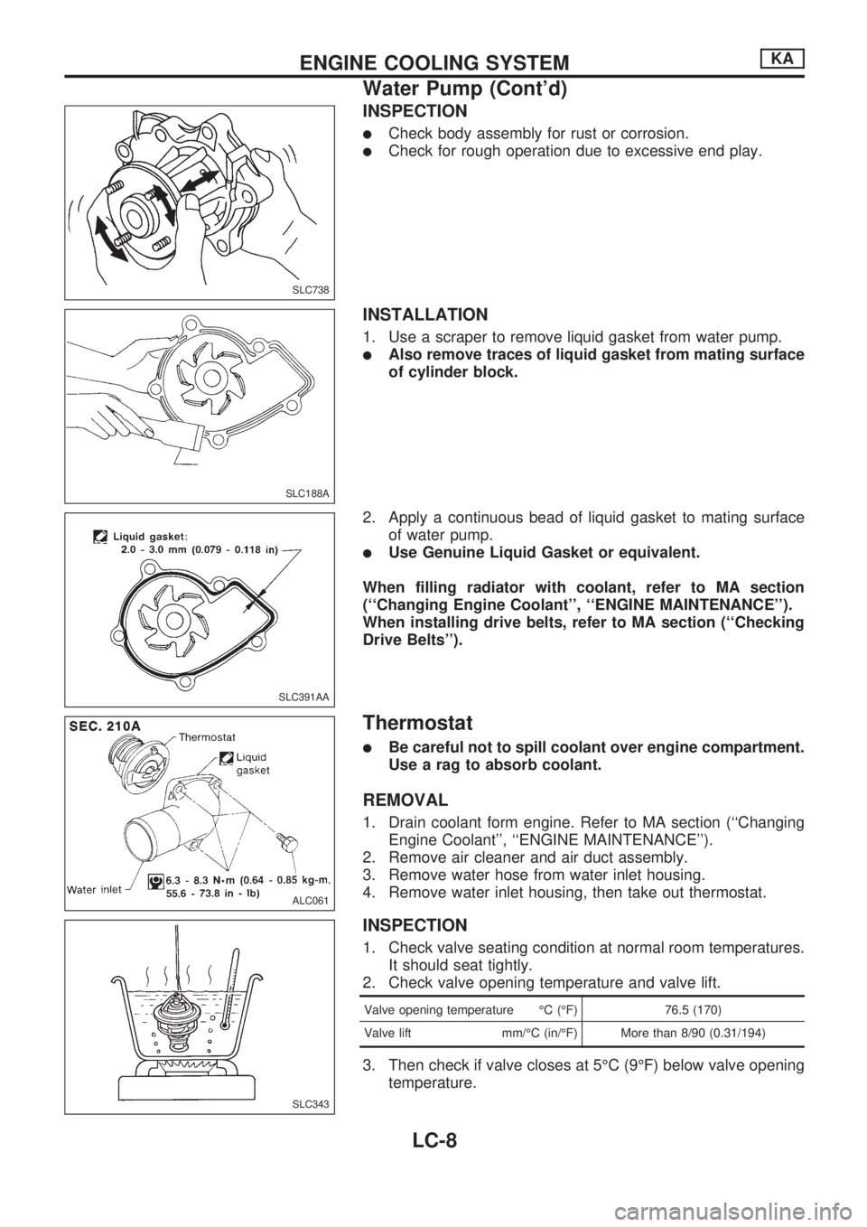
INSPECTION
lCheck body assembly for rust or corrosion.
lCheck for rough operation due to excessive end play.
INSTALLATION
1. Use a scraper to remove liquid gasket from water pump.
lAlso remove traces of liquid gasket from mating surface
of cylinder block.
2. Apply a continuous bead of liquid gasket to mating surface
of water pump.
lUse Genuine Liquid Gasket or equivalent.
When filling radiator with coolant, refer to MA section
(``Changing Engine Coolant'', ``ENGINE MAINTENANCE'').
When installing drive belts, refer to MA section (``Checking
Drive Belts'').
Thermostat
lBe careful not to spill coolant over engine compartment.
Use a rag to absorb coolant.
REMOVAL
1. Drain coolant form engine. Refer to MA section (``Changing
Engine Coolant'', ``ENGINE MAINTENANCE'').
2. Remove air cleaner and air duct assembly.
3. Remove water hose from water inlet housing.
4. Remove water inlet housing, then take out thermostat.
INSPECTION
1. Check valve seating condition at normal room temperatures.
It should seat tightly.
2. Check valve opening temperature and valve lift.
Valve opening temperature ÉC (ÉF) 76.5 (170)
Valve lift mm/ÉC (in/ÉF) More than 8/90 (0.31/194)
3. Then check if valve closes at 5ÉC (9ÉF) below valve opening
temperature.
SLC738
SLC188A
SLC391AA
ALC061
SLC343
ENGINE COOLING SYSTEMKA
Water Pump (Cont'd)
LC-8
Page 949 of 1659

Cooling Fan (Crankshaft driven)
REMOVAL AND INSTALLATION
lDo not release the drive belt tension by removing the fan/
water pump pulley.
lFan coupling cannot be disassembled and should be
replaced as a unit. If front mark
VFis present, install fan so
that side marked
VFfaces the front.
lInstall the drive belt only after the fan and fan coupling to
water pump flange bolts/nuts have been properly torqued.
lProper alignment of these components is essential. Improper
alignment will cause them to wobble and may eventually
cause the fan to separate from the water pump causing
extensive damage.
SLC227B
SLC224B
ENGINE COOLING SYSTEMKA
Radiator (Cont'd)
LC-10
Page 960 of 1659
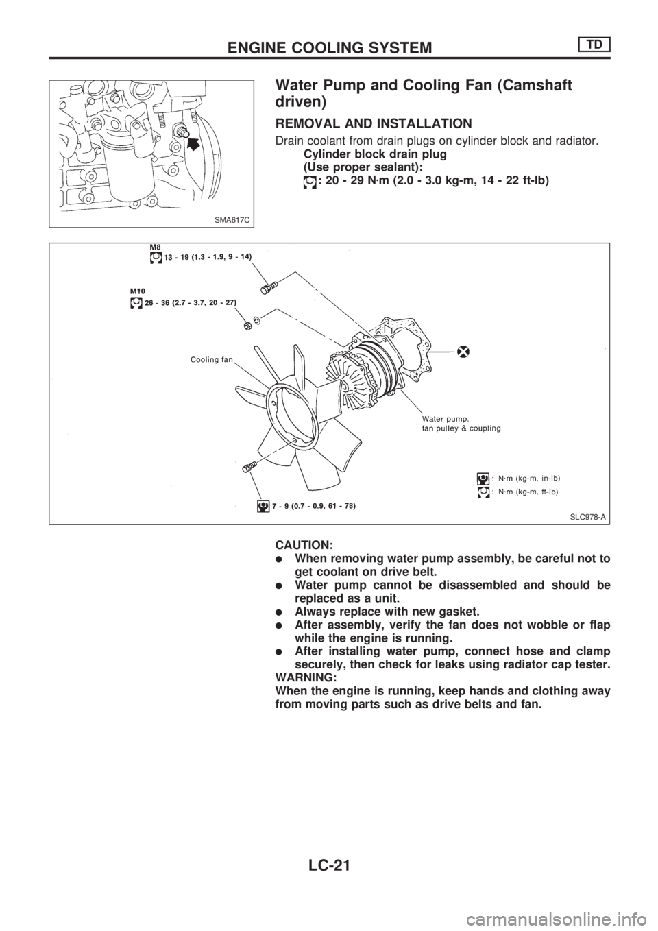
Water Pump and Cooling Fan (Camshaft
driven)
REMOVAL AND INSTALLATION
Drain coolant from drain plugs on cylinder block and radiator.
Cylinder block drain plug
(Use proper sealant):
:20-29Nzm (2.0 - 3.0 kg-m, 14 - 22 ft-lb)
CAUTION:
lWhen removing water pump assembly, be careful not to
get coolant on drive belt.
lWater pump cannot be disassembled and should be
replaced as a unit.
lAlways replace with new gasket.
lAfter assembly, verify the fan does not wobble or flap
while the engine is running.
lAfter installing water pump, connect hose and clamp
securely, then check for leaks using radiator cap tester.
WARNING:
When the engine is running, keep hands and clothing away
from moving parts such as drive belts and fan.
SMA617C
SLC978-A
ENGINE COOLING SYSTEMTD
LC-21
Page 961 of 1659
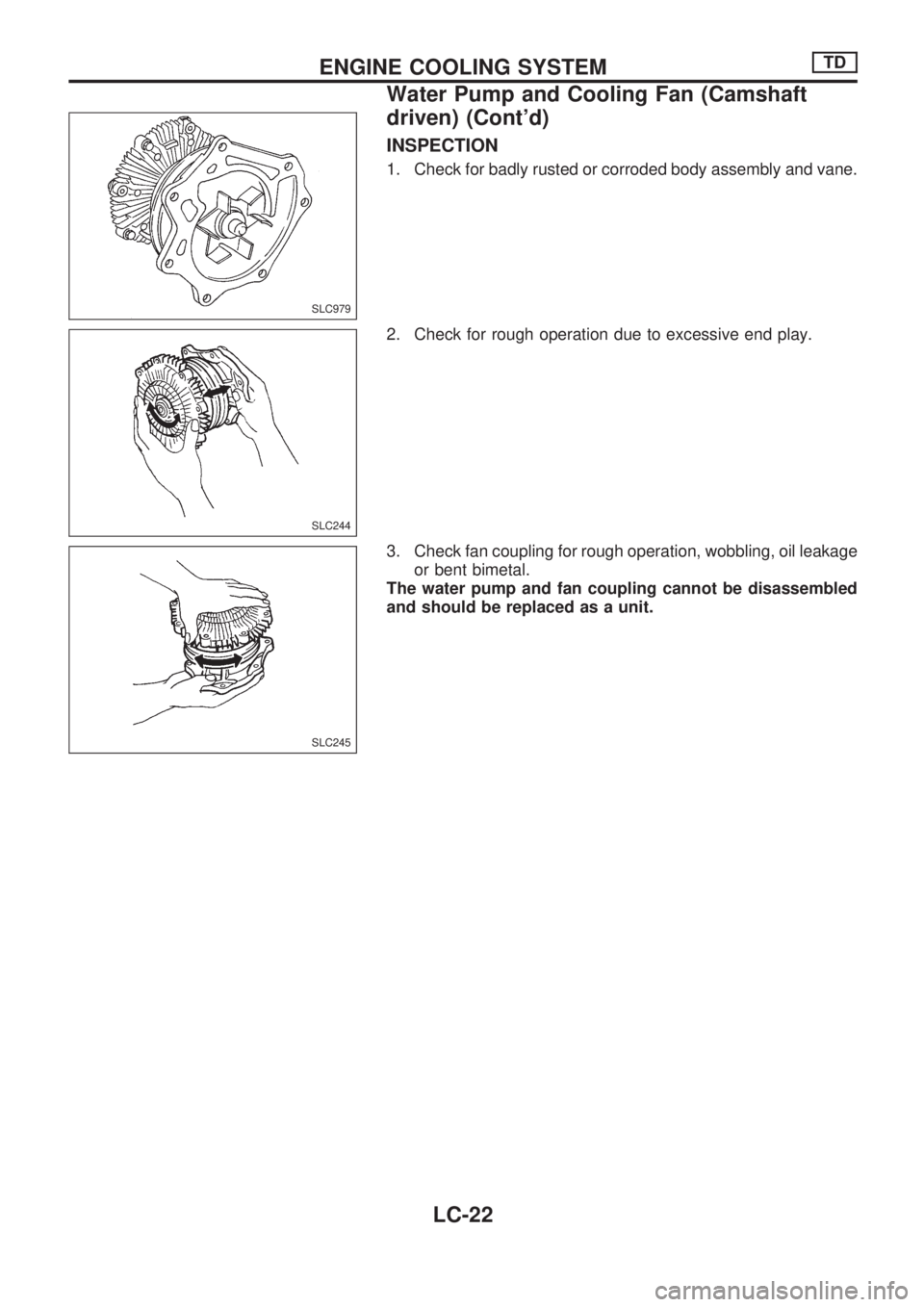
INSPECTION
1. Check for badly rusted or corroded body assembly and vane.
2. Check for rough operation due to excessive end play.
3. Check fan coupling for rough operation, wobbling, oil leakage
or bent bimetal.
The water pump and fan coupling cannot be disassembled
and should be replaced as a unit.
SLC979
SLC244
SLC245
ENGINE COOLING SYSTEMTD
Water Pump and Cooling Fan (Camshaft
driven) (Cont'd)
LC-22
Page 970 of 1659
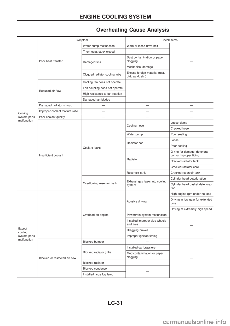
Overheating Cause Analysis
Symptom Check items
Cooling
system parts
malfunctionPoor heat transferWater pump malfunction Worn or loose drive belt
Ð Thermostat stuck closed Ð
Damaged finsDust contamination or paper
clogging
Mechanical damage
Clogged radiator cooling tubeExcess foreign material (rust,
dirt, sand, etc.)
Reduced air flowCooling fan does not operate
ÐÐ Fan coupling does not operate
High resistance to fan rotation
Damaged fan blades
Damaged radiator shroud Ð Ð Ð
Improper coolant mixture ratio Ð Ð Ð
Poor coolant quality Ð Ð Ð
Insufficient coolantCoolant leaksCooling hoseLoose clamp
Cracked hose
Water pump Poor sealing
Radiator capLoose
Poor sealing
RadiatorO-ring for damage, deteriora-
tion or improper fitting
Cracked radiator tank
Cracked radiator core
Reservoir tank Cracked reservoir tank
Overflowing reservoir tankExhaust gas leaks into cooling
systemCylinder head deterioration
Cylinder head gasket deteriora-
tion
Except
cooling
system parts
malfunctionÐ Overload on engineAbusive drivingHigh engine rpm under no load
Driving in low gear for extended
time
Driving at extremely high speed
Powertrain system malfunction
Ð Installed improper size wheels
and tires
Dragging brakes
Improper ignition timing
Blocked or restricted air flowBlocked bumper Ð
Ð Blocked radiator grilleInstalled car brassiere
Mud contamination or paper
clogging
Blocked radiator Ð
Blocked condenser
Ð
Installed large fog lamp
ENGINE COOLING SYSTEM
LC-31
Page 1001 of 1659
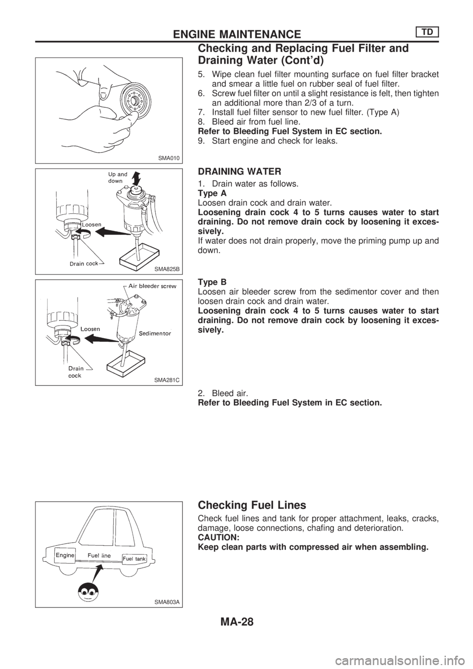
5. Wipe clean fuel filter mounting surface on fuel filter bracket
and smear a little fuel on rubber seal of fuel filter.
6. Screw fuel filter on until a slight resistance is felt, then tighten
an additional more than 2/3 of a turn.
7. Install fuel filter sensor to new fuel filter. (Type A)
8. Bleed air from fuel line.
Refer to Bleeding Fuel System in EC section.
9. Start engine and check for leaks.
DRAINING WATER
1. Drain water as follows.
Type A
Loosen drain cock and drain water.
Loosening drain cock 4 to 5 turns causes water to start
draining. Do not remove drain cock by loosening it exces-
sively.
If water does not drain properly, move the priming pump up and
down.
Type B
Loosen air bleeder screw from the sedimentor cover and then
loosen drain cock and drain water.
Loosening drain cock 4 to 5 turns causes water to start
draining. Do not remove drain cock by loosening it exces-
sively.
2. Bleed air.
Refer to Bleeding Fuel System in EC section.
Checking Fuel Lines
Check fuel lines and tank for proper attachment, leaks, cracks,
damage, loose connections, chafing and deterioration.
CAUTION:
Keep clean parts with compressed air when assembling.
SMA010
SMA825B
SMA281C
SMA803A
ENGINE MAINTENANCETD
Checking and Replacing Fuel Filter and
Draining Water (Cont'd)
MA-28