water pump NISSAN PICK-UP 1998 Owner's Manual
[x] Cancel search | Manufacturer: NISSAN, Model Year: 1998, Model line: PICK-UP, Model: NISSAN PICK-UP 1998Pages: 1659, PDF Size: 53.39 MB
Page 1313 of 1659

EARTH CONNECT TO CONN. NO. CELL CODE
M1/M54 COMBINATION METER (AIR BAG WARNING
LAMP)N5 RS-SRS EL-WARN
COMBINATION METER (CLOCK ILLUMINA-
TION)N6 EL-ILL EL-CLOCK
COMBINATION METER (DIGITAL CLOCK) N6 EL-CLOCK
COMBINATION METER (FUEL GAUGE) N5 EL-METER
COMBINATION METER (HIGH BEAM INDICA-
TOR)N5 EL-H/LAMP EL-DTRL EL-DIMDIP
COMBINATION METER (METER ILLUMINA-
TION)N6 EL-ILL
COMBINATION METER (ODO/TRIP METER
ILLUMINATION)N6 EL-ILL
COMBINATION METER (REAR FOG LAMP
INDICATOR)N6 EL-R/FOG
COMBINATION METER (TURN LH INDICA-
TOR)N6 EL-TURN
COMBINATION METER (TURN RH INDICA-
TOR)N6 EL-TURN
COMBINATION METER (UNIFIED METER
CONTROL UNIT)N5 EC-VSS EC-GLOW EL-METER
COMBINATION METER (WATER TEMP.
GAUGE)N5 EL-METER
DOOR MIRROR REMOTE CONTROL SWITCH N3 EL-MIRROR
FRONT WIPER AMPLIFIER (RHD models with
KA engine)F20 EL-WIPER
FRONT WIPER MOTOR (RHD models with KA
engine)F21 EL-WIPER
HEADLAMP AIMING SWITCH N7 EL-H/AIM
INTERIOR LAMP (Single cab and King cab) R4 EL-INT/L
SPOT LAMP R3 EL-INT/L
FUEL TANK GAUGE UNIT (With electric fuel
pump)C3EC-FPCM EC-F/PUMP EL-METER
EL-WARN
FUEL TANK GAUGE UNIT (With mechanical
fuel pump)C4 EL-METER EL-WARN
LICENSE PLATE LAMP LH (With step bumper) T7 EL-TAIL/L
LICENSE PLATE LAMP LH (Without step
bumper)T6 EL-TAIL/L
LICENSE PLATE LAMP RH (With step bumper) T3 EL-TAIL/L
LICENSE PLATE LAMP RH (Without step
bumper)T5 EL-TAIL/L
REAR COMBINATION LAMP LH (BACK-UP)
(A-chassis models, and except for Europe,
Australia and China)T8 EL-BACK/L
REAR COMBINATION LAMP LH (BACK-UP)
(For Europe, Australia and China except
A-chassis models)T9 EL-BACK/L
REAR COMBINATION LAMP LH (REAR FOG)
(LHD models except A-chassis)T9 EL-R/FOG
REAR COMBINATION LAMP LH (TAIL AND
STOP) (A-chassis models, and except for
Europe, Australia and China)T8 EL-TAIL/L EL-STOP/L
REAR COMBINATION LAMP LH (TAIL AND
STOP) (For Europe, Australia and China except
A-chassis models)T9 EL-TAIL/L EL-STOP/L
REAR COMBINATION LAMP LH (TURN SIG-
NAL) (A-chassis models, and except for
Europe, Australia and China)T8 EL-TURN
REAR COMBINATION LAMP LH (TURN SIG-
NAL) (For Europe, Australia and China except
A-chassis models)T9 EL-TURN
REAR COMBINATION LAMP RH (BACK-UP)
(A-chassis models, and except for Europe, Aus-
tralia and China)T1 EL-BACK/L
REAR COMBINATION LAMP RH (BACK-UP)
(For Europe, Australia and China except
A-chassis models)T2 EL-BACK/L
GROUND DISTRIBUTION
EL-15
Page 1402 of 1659
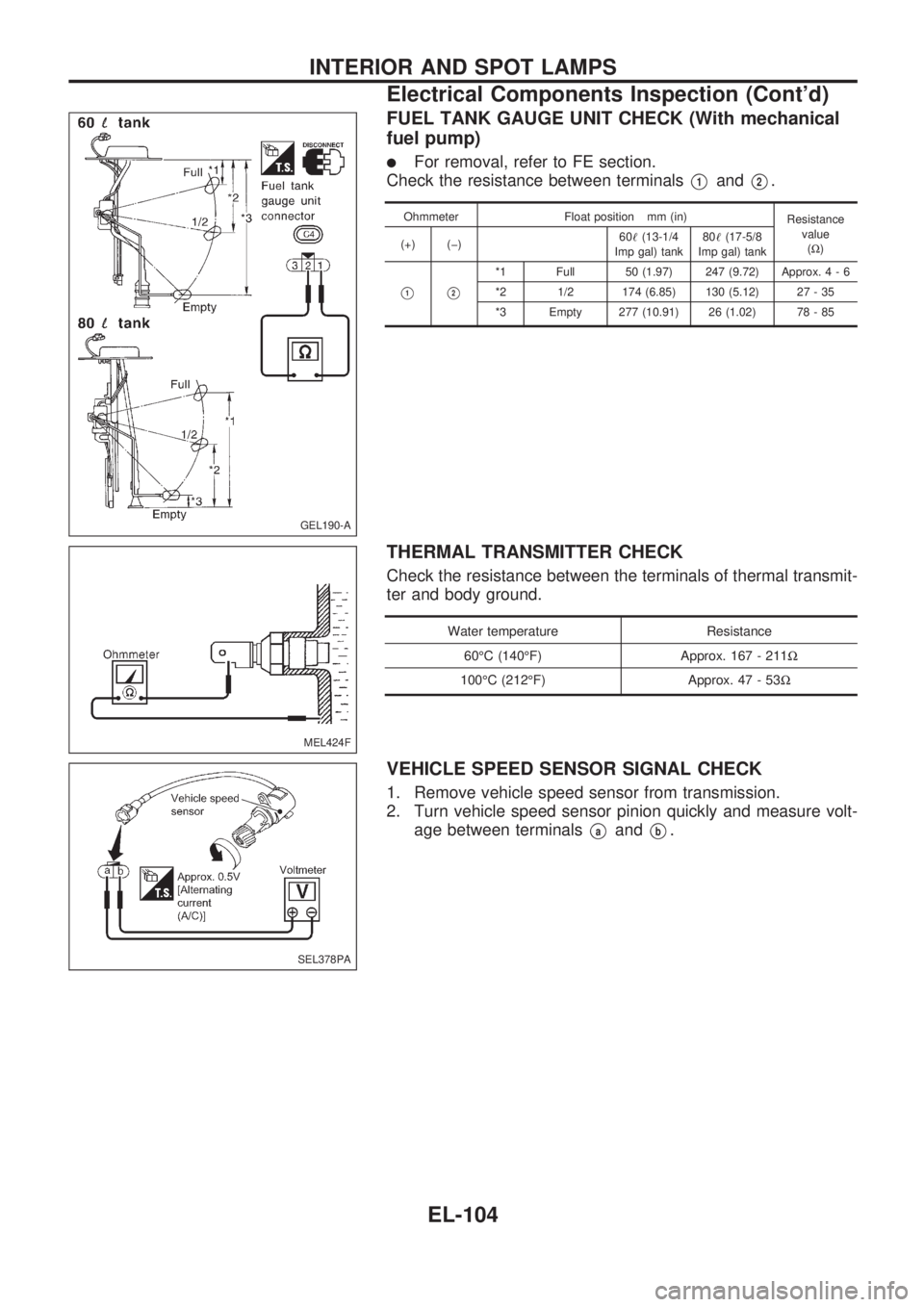
FUEL TANK GAUGE UNIT CHECK (With mechanical
fuel pump)
lFor removal, refer to FE section.
Check the resistance between terminals
V1andV2.
Ohmmeter Float position mm (in)
Resistance
value
(W) (+) (þ)60!(13-1/4
Imp gal) tank80!(17-5/8
Imp gal) tank
V1V2
*1 Full 50 (1.97) 247 (9.72) Approx. 4 - 6
*2 1/2 174 (6.85) 130 (5.12) 27 - 35
*3 Empty 277 (10.91) 26 (1.02) 78 - 85
THERMAL TRANSMITTER CHECK
Check the resistance between the terminals of thermal transmit-
ter and body ground.
Water temperature Resistance
60ÉC (140ÉF) Approx. 167 - 211W
100ÉC (212ÉF) Approx. 47 - 53W
VEHICLE SPEED SENSOR SIGNAL CHECK
1. Remove vehicle speed sensor from transmission.
2. Turn vehicle speed sensor pinion quickly and measure volt-
age between terminals
VaandVb.
GEL190-A
MEL424F
SEL378PA
INTERIOR AND SPOT LAMPS
Electrical Components Inspection (Cont'd)
EL-104
Page 1592 of 1659
CAUTION:
lWhen installing sliding parts (bearings, pistons, etc.),
lubricate contacting surfaces with new engine oil.
lPlace removed parts such as bearings and bearing caps
in their proper order and direction.
lWhen installing connecting rod nuts and main bearing
cap bolts, apply new engine oil to threads and seating
surfaces.
lDo not allow any magnetic materials to contact the ring
gear teeth of flywheel or drive plate.
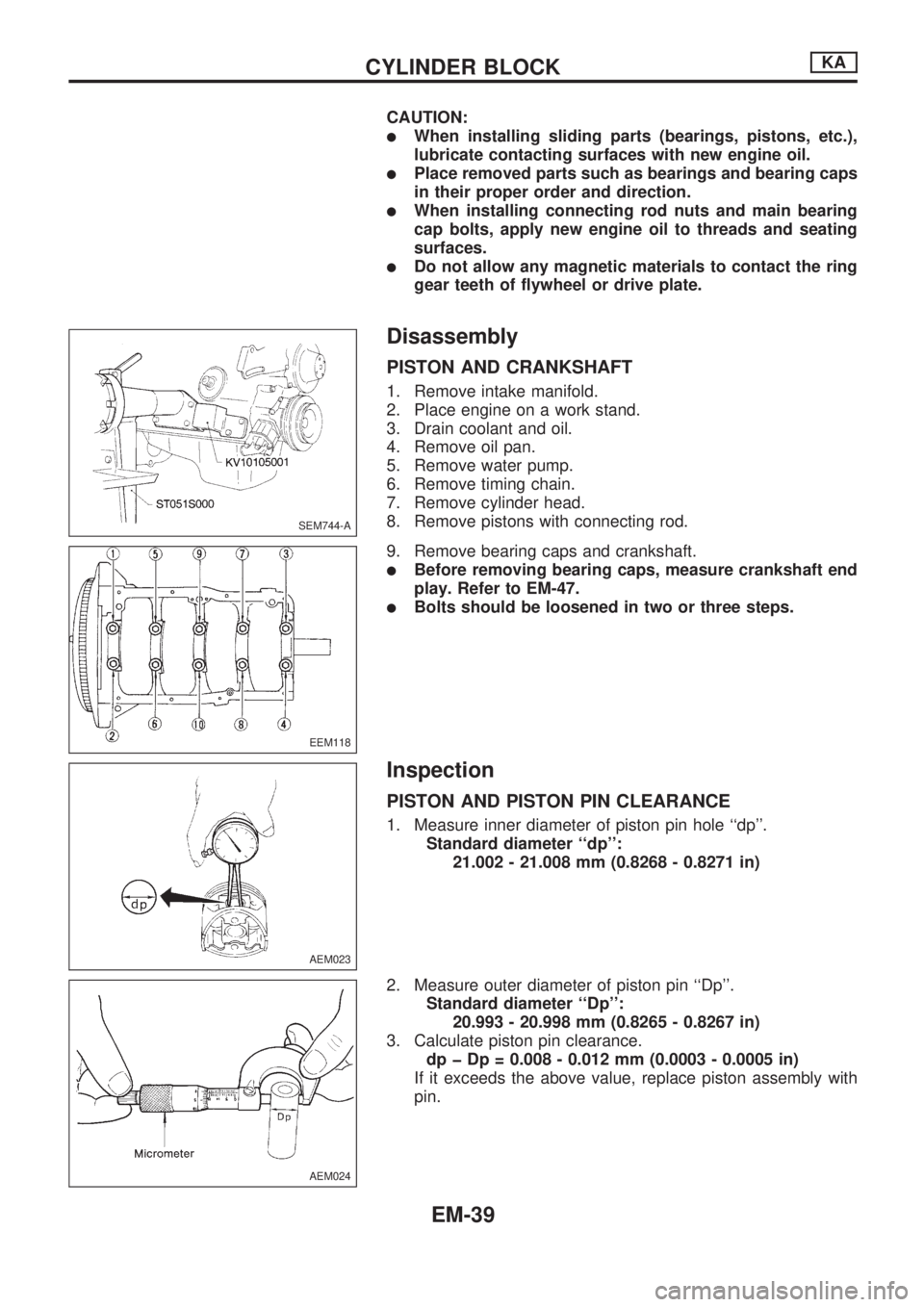
Disassembly
PISTON AND CRANKSHAFT
1. Remove intake manifold.
2. Place engine on a work stand.
3. Drain coolant and oil.
4. Remove oil pan.
5. Remove water pump.
6. Remove timing chain.
7. Remove cylinder head.
8. Remove pistons with connecting rod.
9. Remove bearing caps and crankshaft.
lBefore removing bearing caps, measure crankshaft end
play. Refer to EM-47.
lBolts should be loosened in two or three steps.
Inspection
PISTON AND PISTON PIN CLEARANCE
1. Measure inner diameter of piston pin hole ``dp''.
Standard diameter ``dp'':
21.002 - 21.008 mm (0.8268 - 0.8271 in)
2. Measure outer diameter of piston pin ``Dp''.
Standard diameter ``Dp'':
20.993 - 20.998 mm (0.8265 - 0.8267 in)
3. Calculate piston pin clearance.
dp þ Dp = 0.008 - 0.012 mm (0.0003 - 0.0005 in)
If it exceeds the above value, replace piston assembly with
pin.
SEM744-A
EEM118
AEM023
AEM024
CYLINDER BLOCKKA
EM-39
Page 1625 of 1659

Disassembly
PISTON AND CRANKSHAFT
1. Remove oil filter.
2. Place engine on work stand.
3. Drain coolant and oil.
4. Remove drive belts.
5. Remove cylinder head.
6. Remove oil pan.
7. Remove crankshaft pulley.
8. Remove water pump.
9. Remove timing gear case.
lRemove dust cover with a seal cutter.
lIf the timing case is hard to remove due to liquid gasket,
pry it off with a suitable tool at the cutout section.
SEM650B
SEM651B
DEM045
DEM062
DEM046
ENGINE OVERHAULTD
EM-72