oil type NISSAN PICK-UP 1998 Repair Manual
[x] Cancel search | Manufacturer: NISSAN, Model Year: 1998, Model line: PICK-UP, Model: NISSAN PICK-UP 1998Pages: 1659, PDF Size: 53.39 MB
Page 27 of 1659
Disassembly
WARNING:
Do not place your fingers in front of piston.
CAUTION:
lDo not scratch or score cylinder wall.
lCL28VD type front disc brake uses plastic pistons,
handle them carefully.
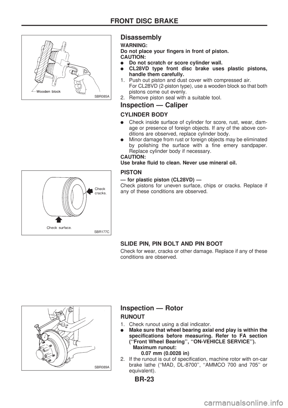
1. Push out piston and dust cover with compressed air.
For CL28VD (2-piston type), use a wooden block so that both
pistons come out evenly.
2. Remove piston seal with a suitable tool.
Inspection Ð Caliper
CYLINDER BODY
lCheck inside surface of cylinder for score, rust, wear, dam-
age or presence of foreign objects. If any of the above con-
ditions are observed, replace cylinder body.
lMinor damage from rust or foreign objects may be eliminated
by polishing the surface with a fine emery sandpaper.
Replace cylinder body if necessary.
CAUTION:
Use brake fluid to clean. Never use mineral oil.
PISTON
Ð for plastic piston (CL28VD) Ð
Check pistons for uneven surface, chips or cracks. Replace if
any of these conditions are observed.
SLIDE PIN, PIN BOLT AND PIN BOOT
Check for wear, cracks or other damage. Replace if any of these
conditions are observed.
Inspection Ð Rotor
RUNOUT
1. Check runout using a dial indicator.
lMake sure that wheel bearing axial end play is within the
specifications before measuring. Refer to FA section
(``Front Wheel Bearing'', ``ON-VEHICLE SERVICE'').
Maximum runout:
0.07 mm (0.0028 in)
2. If the runout is out of specification, machine rotor with on-car
brake lathe (``MAD, DL-8700'', ``AMMCO 700 and 705'' or
equivalent).
SBR085A
SBR177C
SBR089A
FRONT DISC BRAKE
BR-23
Page 431 of 1659
Service Data and Specifications (SDS)
ALTERNATOR
TypeLR160-727C LR160-728C
HITACHI
Applied model KA24 TD25
Nominal rating V-A 12-60
Ground polarityNegative
Minimum revolution under no-load
(When 13.5V is applied) rpmLess than 1,000
Hot output current A/rpmMore than 17/1,300
More than 48/2,500
More than 57/5,000
(When 13.5V is applied)
Regulated output voltage V 14.1 - 14.7
Minimum length of brush
mm (in)6.0 (0.236)
Brush spring pressure
N (g, oz)1.0 - 3.4 (102 - 350, 3.60 - 12.34)
Slip ring minimum outer diameter
mm (in)26.0 (1.024)
Rotor (Field coil) resistanceW2.58
SEL049Z
CHARGING SYSTEM
Assembly (Cont'd)
EL-41
Page 439 of 1659
Bulb Replacement
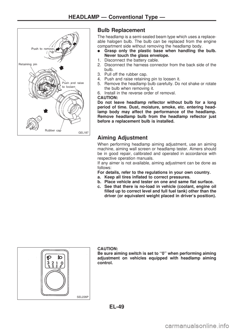
The headlamp is a semi-sealed beam type which uses a replace-
able halogen bulb. The bulb can be replaced from the engine
compartment side without removing the headlamp body.
lGrasp only the plastic base when handling the bulb.
Never touch the glass envelope.
1. Disconnect the battery cable.
2. Disconnect the harness connector from the back side of the
bulb.
3. Pull off the rubber cap.
4. Push and raise retaining pin to loosen it.
5. Remove the headlamp bulb carefully. Do not shake or rotate
the bulb when removing it.
6. Install in the reverse order of removal.
CAUTION:
Do not leave headlamp reflector without bulb for a long
period of time. Dust, moisture, smoke, etc. entering head-
lamp body may affect the performance of the headlamp.
Remove headlamp bulb from the headlamp reflector just
before a replacement bulb is installed.
Aiming Adjustment
When performing headlamp aiming adjustment, use an aiming
machine, aiming wall screen or headlamp tester. Aimers should
be in good repair, calibrated and operated in accordance with
respective operation manuals.
If any aimer is not available, aiming adjustment can be done as
follows:
For details, refer to the regulations in your own country.
a. Keep all tires inflated to correct pressures.
b. Place vehicle and tester on one and same flat surface.
c. See that there is no-load in vehicle (coolant, engine oil
filled up to correct level and full fuel tank) other than the
driver (or equivalent weight placed in driver's position).
CAUTION:
Be sure aiming switch is set to ``0'' when performing aiming
adjustment on vehicles equipped with headlamp aiming
control.
GEL187
SEL226P
HEADLAMP Ð Conventional Type Ð
EL-49
Page 506 of 1659
Electrical Components Inspection
FUEL WARNING LAMP SENSOR CHECK
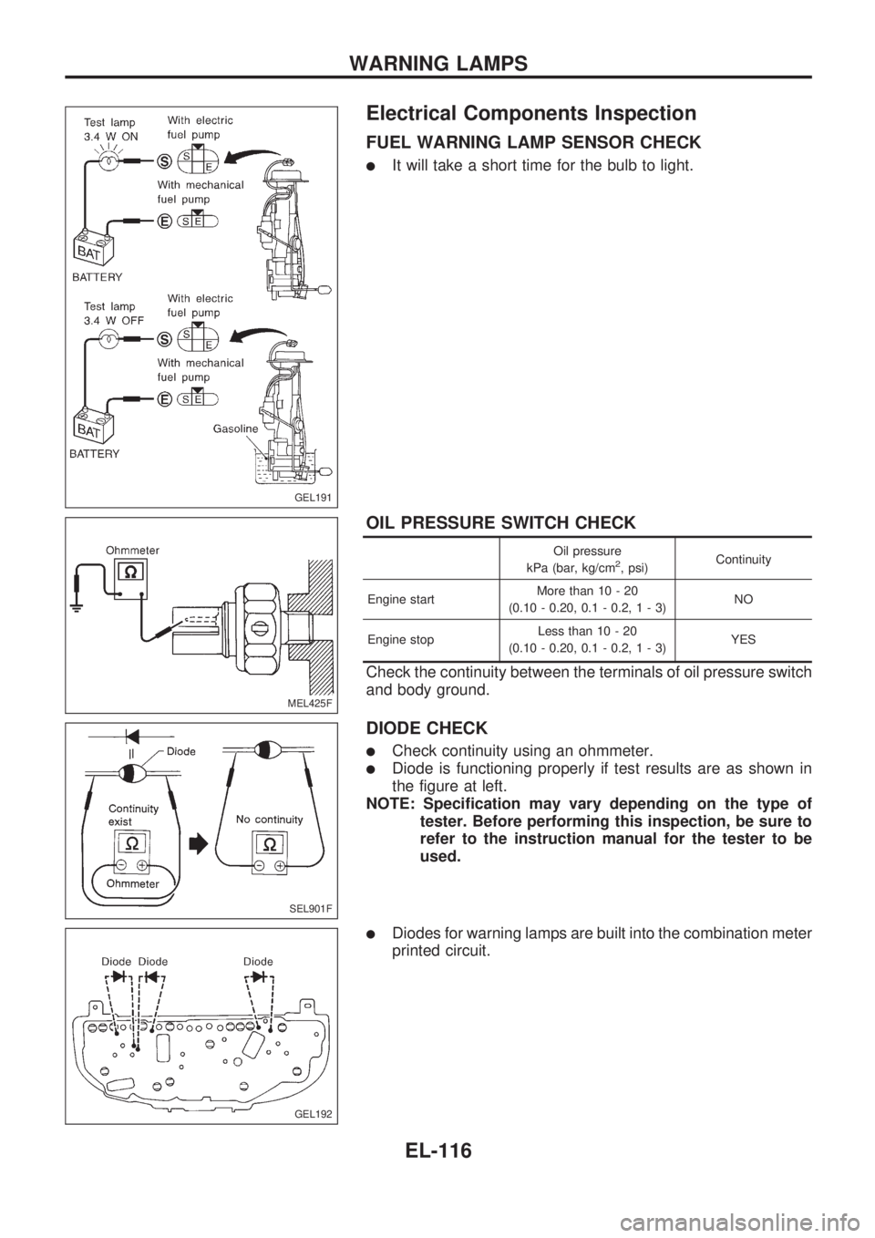
lIt will take a short time for the bulb to light.
OIL PRESSURE SWITCH CHECK
Oil pressure
kPa (bar, kg/cm2, psi)Continuity
Engine startMore than 10 - 20
(0.10 - 0.20, 0.1 - 0.2,1-3)NO
Engine stopLess than 10 - 20
(0.10 - 0.20, 0.1 - 0.2,1-3)YES
Check the continuity between the terminals of oil pressure switch
and body ground.
DIODE CHECK
lCheck continuity using an ohmmeter.
lDiode is functioning properly if test results are as shown in
the figure at left.
NOTE: Specification may vary depending on the type of
tester. Before performing this inspection, be sure to
refer to the instruction manual for the tester to be
used.
lDiodes for warning lamps are built into the combination meter
printed circuit.
GEL191
MEL425F
SEL901F
GEL192
WARNING LAMPS
EL-116
Page 678 of 1659
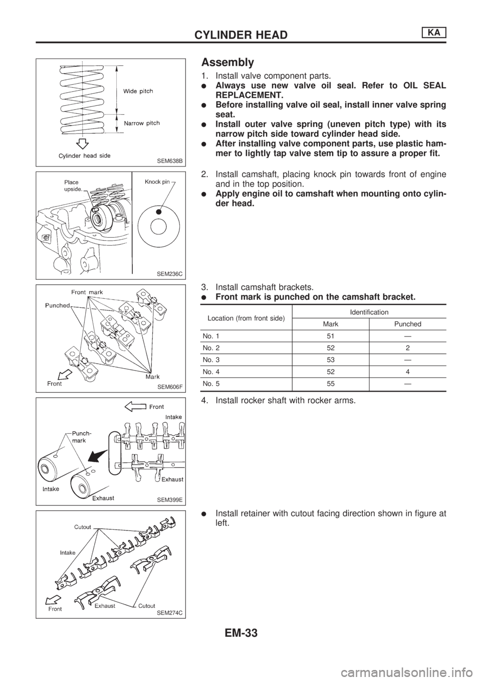
Assembly
1. Install valve component parts.
lAlways use new valve oil seal. Refer to OIL SEAL
REPLACEMENT.
lBefore installing valve oil seal, install inner valve spring
seat.
lInstall outer valve spring (uneven pitch type) with its
narrow pitch side toward cylinder head side.
lAfter installing valve component parts, use plastic ham-
mer to lightly tap valve stem tip to assure a proper fit.
2. Install camshaft, placing knock pin towards front of engine
and in the top position.
lApply engine oil to camshaft when mounting onto cylin-
der head.
3. Install camshaft brackets.
lFront mark is punched on the camshaft bracket.
Location (from front side)Identification
Mark Punched
No. 1 51 Ð
No. 2 52 2
No. 3 53 Ð
No. 4 52 4
No. 5 55 Ð
4. Install rocker shaft with rocker arms.
lInstall retainer with cutout facing direction shown in figure at
left.
SEM638B
SEM236C
SEM606F
SEM399E
SEM274C
CYLINDER HEADKA
EM-33
Page 707 of 1659
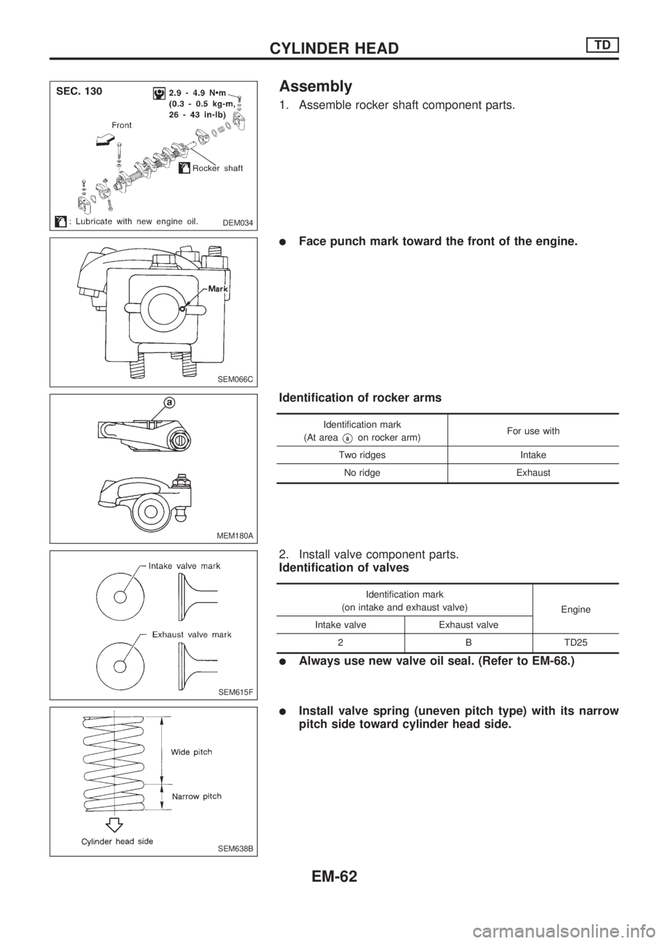
Assembly
1. Assemble rocker shaft component parts.
lFace punch mark toward the front of the engine.
Identification of rocker arms
Identification mark
(At area
Vaon rocker arm)For use with
Two ridges Intake
No ridge Exhaust
2. Install valve component parts.
Identification of valves
Identification mark
(on intake and exhaust valve)
Engine
Intake valve Exhaust valve
2 B TD25
lAlways use new valve oil seal. (Refer to EM-68.)
lInstall valve spring (uneven pitch type) with its narrow
pitch side toward cylinder head side.
DEM034
SEM066C
MEM180A
SEM615F
SEM638B
CYLINDER HEADTD
EM-62
Page 712 of 1659
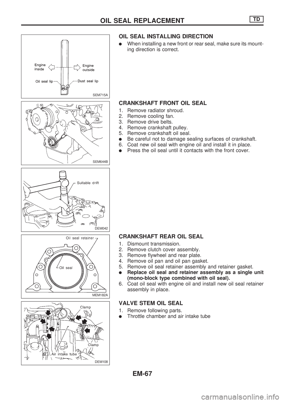
OIL SEAL INSTALLING DIRECTION
lWhen installing a new front or rear seal, make sure its mount-
ing direction is correct.
CRANKSHAFT FRONT OIL SEAL
1. Remove radiator shroud.
2. Remove cooling fan.
3. Remove drive belts.
4. Remove crankshaft pulley.
5. Remove crankshaft oil seal.
lBe careful not to damage sealing surfaces of crankshaft.
6. Coat new oil seal with engine oil and install it in place.
lPress the oil seal until it contacts with the front cover.
CRANKSHAFT REAR OIL SEAL
1. Dismount transmission.
2. Remove clutch cover assembly.
3. Remove flywheel and rear plate.
4. Remove oil pan and oil pan gasket.
5. Remove oil seal retainer assembly and retainer gasket.
lReplace oil seal and retainer assembly as a single unit
(mono-block type combined with oil seal).
6. Coat oil seal with engine oil and install new oil seal retainer
assembly in place.
VALVE STEM OIL SEAL
1. Remove following parts.
lThrottle chamber and air intake tube
SEM715A
SEM644B
DEM042
MEM182A
DEM108
.
OIL SEAL REPLACEMENTTD
EM-67
Page 733 of 1659
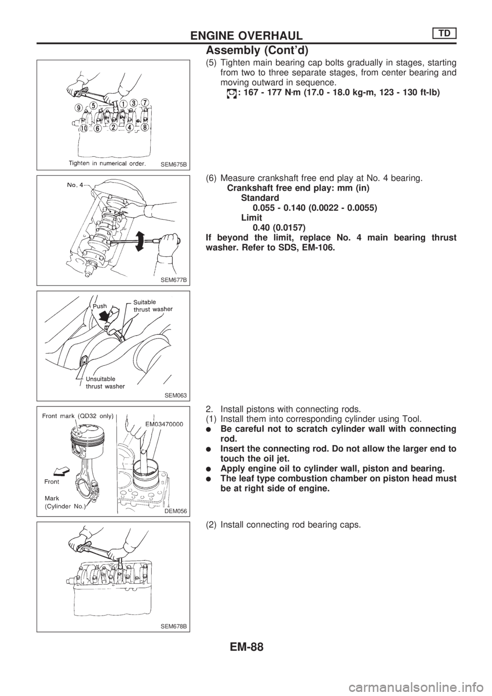
(5) Tighten main bearing cap bolts gradually in stages, starting
from two to three separate stages, from center bearing and
moving outward in sequence.
: 167 - 177 Nzm (17.0 - 18.0 kg-m, 123 - 130 ft-lb)
(6) Measure crankshaft free end play at No. 4 bearing.
Crankshaft free end play: mm (in)
Standard
0.055 - 0.140 (0.0022 - 0.0055)
Limit
0.40 (0.0157)
If beyond the limit, replace No. 4 main bearing thrust
washer. Refer to SDS, EM-106.
2. Install pistons with connecting rods.
(1) Install them into corresponding cylinder using Tool.
lBe careful not to scratch cylinder wall with connecting
rod.
lInsert the connecting rod. Do not allow the larger end to
touch the oil jet.
lApply engine oil to cylinder wall, piston and bearing.
lThe leaf type combustion chamber on piston head must
be at right side of engine.
(2) Install connecting rod bearing caps.
SEM675B
SEM677B
SEM063
DEM056.DEM056
SEM678B
ENGINE OVERHAULTD
Assembly (Cont'd)
EM-88
Page 810 of 1659
DIESEL ENGINE*:
For Europe: diesel fuel of above 50 cetane
* If two types of diesel fuel are available, use summer or win-
ter fuel properly according to the following temperature con-
ditions.
lAbove þ7ÉC (20ÉF) ... Summer type diesel fuel.
lBelow þ7ÉC (20ÉF) ... Winter type diesel fuel.
CAUTION:
lDo not use home heating oil, gasoline, or other alternate
fuels in your diesel engine. The use of those can cause
engine damage.
lDo not use summer fuel at temperature below þ7ÉC
(20ÉF). The cold temperature will cause wax to form in
the fuel. As a result, it may prevent the engine from run-
ning smoothly.
lDo not add gasoline or other alternate fuels to diesel
fuel.
Precautions for Air Conditioning
Use an approved refrigerant recovery unit any time the air con-
ditioning system must be discharged. Refer to HA section
(``HFC-134a (R-134a) Service Procedure'', ``SERVICE PRO-
CEDURES'') for specific instructions.
PRECAUTIONS
Precautions for Fuel (Cont'd)
GI-6
Page 812 of 1659
lThe followingSYMBOLS AND ABBREVIATIONSare used:
,: Tightening torque
: Should be lubricated with grease.
Unless otherwise indicated, use
recommended multi-purpose
grease.
: Should be lubricated with oil.
: Sealing point
: Checking point
: Always replace after every disas-
sembly.
VP: Apply petroleum jelly.
: Apply ATF.
.: Select with proper thickness.
>: Adjustment is required.
SDS : Service Data and Specifications
LH, RH : Left-Hand, Right-Hand
FR, RR : Front, Rear
M/T : Manual Transaxle/Transmission
A/T : Automatic Transaxle/Transmission
,
4WD : 4-Wheel Drive
2WD : 2-Wheel Drive
A/C : Air Conditioner
P/S : Power Steering
SST : Special Service Tools
SAE : Society of Automotive Engineers,
Inc.
ATF : Automatic Transmission Fluid
D
1: Drive range 1st gear
D
2: Drive range 2nd gear
D
3: Drive range 3rd gear
D
4: Drive range 4th gear
OD : Overdrive
2
2: 2nd range 2nd gear
2
1: 2nd range 1st gear
1
2: 1st range 2nd gear
1
1: 1st range 1st gear
lTheUNITSgiven in this manual are primarily expressed as the SI UNIT (International System of Unit),
and alternatively expressed in the metric system and in the yard/pound system.
``Example''
Tightening torque:
59 - 78 N´m (6.0 - 8.0 kg-m, 43 - 58 ft-lb)
lTROUBLE DIAGNOSESare included in sections dealing with complicated components.
lSERVICE DATA AND SPECIFICATIONSare contained at the end of each section for quick reference
of data.
lThe captionsWARNINGandCAUTIONwarn you of steps that must be followed to prevent personal
injury and/or damage to some part of the vehicle.
WARNINGindicates the possibility of personal injury if instructions are not followed.
CAUTIONindicates the possibility of component damage if instructions are not followed.
BOLD TYPED STATEMENTSexceptWARNINGandCAUTIONgive you helpful information.
HOW TO USE THIS MANUAL
GI-8