brake sensor NISSAN PICK-UP 1998 Repair Manual
[x] Cancel search | Manufacturer: NISSAN, Model Year: 1998, Model line: PICK-UP, Model: NISSAN PICK-UP 1998Pages: 1659, PDF Size: 53.39 MB
Page 5 of 1659
Supplemental Restraint System (SRS) ``AIR
BAG'' (4WD models)
The Supplemental Restraint System ``AIR BAG'', used along with a seat belt, helps to reduce the risk or
severity of injury to the driver in a frontal collision. The Supplemental Restraint System consists of air bag
module (located in the center of the steering wheel), a diagnosis sensor unit, warning lamp, wiring harness
and spiral cable. Information necessary to service the system safely is included in theRS sectionof this
Service Manual.
WARNING:
lTo avoid rendering the SRS inoperative, which could increase the risk of personal injury or death
in the event of a collision which would result in air bag inflation, all maintenance must be per-
formed by an authorized NISSAN dealer.
lImproper maintenance, including incorrect removal and installation of the SRS, can lead to per-
sonal injury caused by unintentional activation of the system.
lDo not use electrical test equipment on any circuit related to the SRS unless instructed to in this
Service Manual. SRS wiring harnesses are covered with yellow insulation either just before the
harness connectors or for the complete harness, for easy identification.
Supplemental Restraint System (SRS) ``AIR
BAG'' (2WD models)
The Supplemental Restraint System ``AIR BAG'', used along with a seat belt, helps to reduce the risk or
severity of injury to the driver in a frontal collision. The Supplemental Restraint System consists of an air
bag module (located in the center of the steering wheel), a diagnosis sensor unit, warning lamp and spiral
cable. Information necessary to service the system safely is included in theRS sectionof this Service
Manual.
WARNING:
lTo avoid rendering the SRS inoperative, which could increase the risk of personal injury or death
in the event of a collision which would result in air bag inflation, all maintenance must be per-
formed by an authorized NISSAN dealer.
lImproper maintenance, including incorrect removal and installation of the SRS, can lead to per-
sonal injury caused by unintentional activation of the system.
lDo not use electrical test equipment on any circuit related to the SRS.
Precautions for Brake System
lUse brake fluid DOT 3 or DOT 4*1.
lNever reuse drained brake fluid.
lBe careful not to splash brake fluid on painted areas; it
may cause paint damage. If brake fluid is splashed on
painted areas, wash it away with water immediately.
lTo clean master cylinder parts, disc brake caliper parts
or wheel cylinder parts, use clean brake fluid.
lNever use mineral oils such as gasoline or kerosene.
They will ruin rubber parts of the hydraulic system.
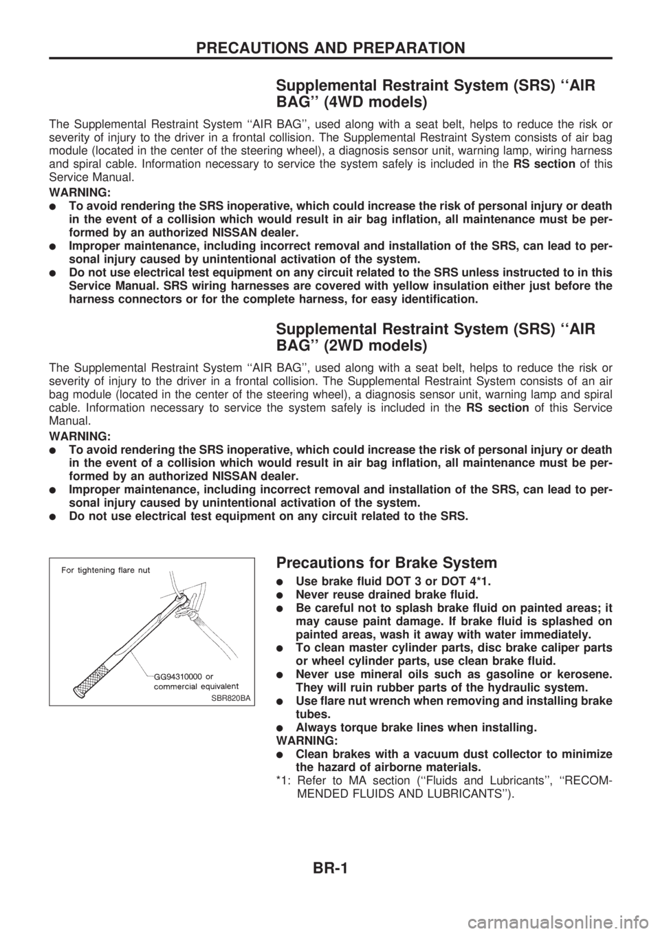
lUse flare nut wrench when removing and installing brake
tubes.
lAlways torque brake lines when installing.
WARNING:
lClean brakes with a vacuum dust collector to minimize
the hazard of airborne materials.
*1: Refer to MA section (``Fluids and Lubricants'', ``RECOM-
MENDED FLUIDS AND LUBRICANTS'').
SBR820BA
PRECAUTIONS AND PREPARATION
BR-1
Page 13 of 1659
INSPECTION
1. Ensure vehicle is unladen condition*.
* Fuel, radiator coolant and engine oil full. Spare tire, jack,
hand tools and mats in designated positions.
2. Have a driver sit in the driver's seat and one person sit on
the rear of the vehicle. Then have the person on the rear of
the vehicle slowly get off. This is necessary to stabilize sus-
pension deflection.
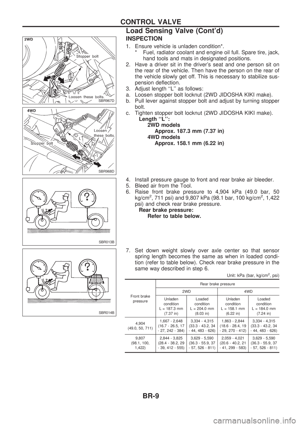
3. Adjust length ``L'' as follows:
a. Loosen stopper bolt locknut (2WD JIDOSHA KIKI make).
b. Pull lever against stopper bolt and adjust by turning stopper
bolt.
c. Tighten stopper bolt locknut (2WD JIDOSHA KIKI make).
Length ``L'':
2WD models
Approx. 187.3 mm (7.37 in)
4WD models
Approx. 158.1 mm (6.22 in)
4. Install pressure gauge to front and rear brake air bleeder.
5. Bleed air from the Tool.
6. Raise front brake pressure to 4,904 kPa (49.0 bar, 50
kg/cm
2, 711 psi) and 9,807 kPa (98.1 bar, 100 kg/cm2, 1,422
psi) and check rear brake pressure.
Rear brake pressure:
Refer to table below.
7. Set down weight slowly over axle center so that sensor
spring length becomes the same as when in loaded condi-
tion (refer to table below). Check rear brake pressure in the
same way described in step 6.
Unit: kPa (bar, kg/cm2, psi)
Front brake
pressureRear brake pressure
2WD 4WD
Unladen
condition
L = 187.3 mm
(7.37 in)Loaded
condition
L = 204.0 mm
(8.03 in)Unladen
condition
L = 158.1 mm
(6.22 in)Loaded
condition
L = 184.0 mm
(7.24 in)
4,904
(49.0, 50, 711)1,667 - 2,648
(16.7 - 26.5, 17
- 27, 242 - 384)3,334 - 4,315
(33.3 - 43.2, 34
- 44, 483 - 626)1,863 - 2,844
(18.6 - 28.4, 19
- 29, 270 - 412)3,334 - 4,315
(33.3 - 43.2, 34
- 44, 483 - 626)
9,807
(98.1, 100,
1,422)2,844 - 3,825
(28.4 - 38.2, 29
- 39, 412 - 555)3,629 - 5,590
(36.3 - 55.9, 37
- 57, 526 - 811)2,059 - 4,021
(20.6 - 40.2, 21
- 41, 299 - 583)3,629 - 5,590
(36.3 - 55.9, 37
- 57, 526 - 811)
SBR967D
SBR968D
SBR013B
SBR014B
CONTROL VALVE
Load Sensing Valve (Cont'd)
BR-9
Page 37 of 1659
System Components
System Description
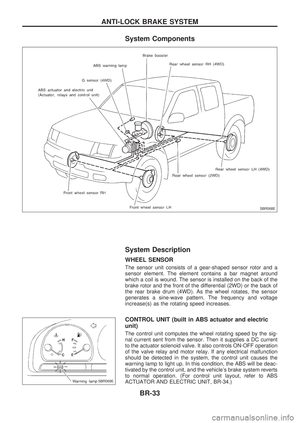
WHEEL SENSOR
The sensor unit consists of a gear-shaped sensor rotor and a
sensor element. The element contains a bar magnet around
which a coil is wound. The sensor is installed on the back of the
brake rotor and the front of the differential (2WD) or the back of
the rear brake drum (4WD). As the wheel rotates, the sensor
generates a sine-wave pattern. The frequency and voltage
increase(s) as the rotating speed increases.
CONTROL UNIT (built in ABS actuator and electric
unit)
The control unit computes the wheel rotating speed by the sig-
nal current sent from the sensor. Then it supplies a DC current
to the actuator solenoid valve. It also controls ON-OFF operation
of the valve relay and motor relay. If any electrical malfunction
should be detected in the system, the control unit causes the
warning lamp to light up. In this condition, the ABS will be deac-
tivated by the control unit, and the vehicle's brake system reverts
to normal operation. (For control unit layout, refer to ABS
ACTUATOR AND ELECTRIC UNIT, BR-34.)
SBR068E
SBR069E
ANTI-LOCK BRAKE SYSTEM
BR-33
Page 38 of 1659
G SENSOR (4WD models only)
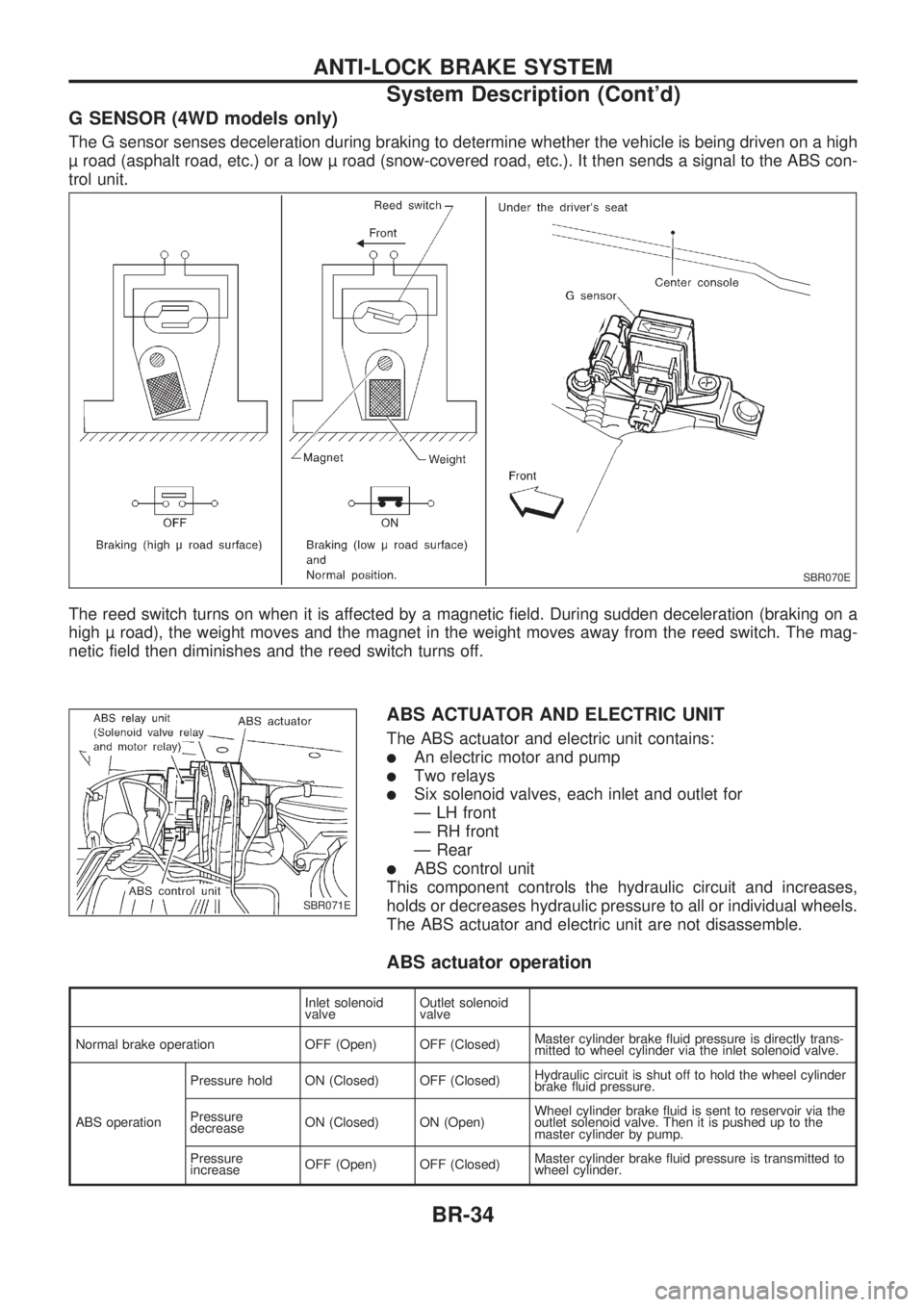
The G sensor senses deceleration during braking to determine whether the vehicle is being driven on a high
road (asphalt road, etc.) or a low road (snow-covered road, etc.). It then sends a signal to the ABS con-
trol unit.
The reed switch turns on when it is affected by a magnetic field. During sudden deceleration (braking on a
high road), the weight moves and the magnet in the weight moves away from the reed switch. The mag-
netic field then diminishes and the reed switch turns off.
ABS ACTUATOR AND ELECTRIC UNIT
The ABS actuator and electric unit contains:
lAn electric motor and pump
lTwo relays
lSix solenoid valves, each inlet and outlet for
Ð LH front
Ð RH front
Ð Rear
lABS control unit
This component controls the hydraulic circuit and increases,
holds or decreases hydraulic pressure to all or individual wheels.
The ABS actuator and electric unit are not disassemble.
ABS actuator operation
Inlet solenoid
valveOutlet solenoid
valve
Normal brake operation OFF (Open) OFF (Closed)Master cylinder brake fluid pressure is directly trans-
mitted to wheel cylinder via the inlet solenoid valve.
ABS operationPressure hold ON (Closed) OFF (Closed)Hydraulic circuit is shut off to hold the wheel cylinder
brake fluid pressure.
Pressure
decreaseON (Closed) ON (Open)Wheel cylinder brake fluid is sent to reservoir via the
outlet solenoid valve. Then it is pushed up to the
master cylinder by pump.
Pressure
increaseOFF (Open) OFF (Closed)Master cylinder brake fluid pressure is transmitted to
wheel cylinder.
SBR070E
SBR071E
ANTI-LOCK BRAKE SYSTEM
System Description (Cont'd)
BR-34
Page 39 of 1659
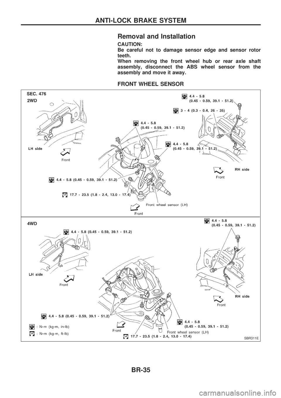
Removal and Installation
CAUTION:
Be careful not to damage sensor edge and sensor rotor
teeth.
When removing the front wheel hub or rear axle shaft
assembly, disconnect the ABS wheel sensor from the
assembly and move it away.
FRONT WHEEL SENSOR
SBR311E
ANTI-LOCK BRAKE SYSTEM
BR-35
Page 40 of 1659
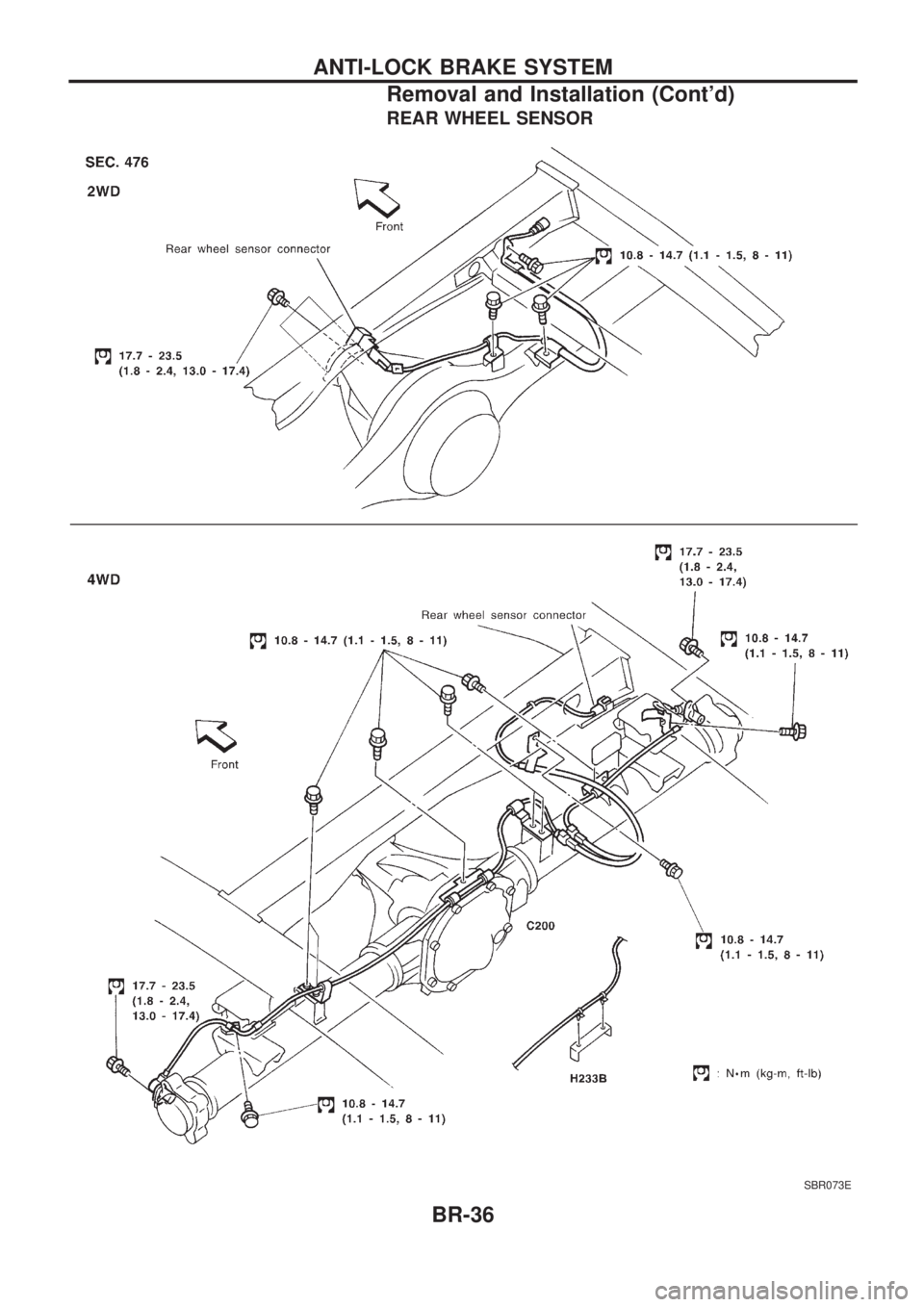
REAR WHEEL SENSOR
SBR073E
ANTI-LOCK BRAKE SYSTEM
Removal and Installation (Cont'd)
BR-36
Page 41 of 1659
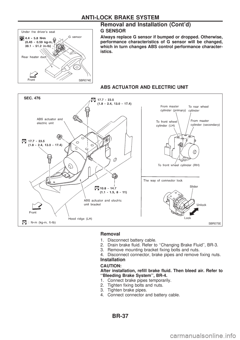
G SENSOR
Always replace G sensor if bumped or dropped. Otherwise,
performance characteristics of G sensor will be changed,
which in turn changes ABS control performance character-
istics.
ABS ACTUATOR AND ELECTRIC UNIT
Removal
1. Disconnect battery cable.
2. Drain brake fluid. Refer to ``Changing Brake Fluid'', BR-3.
3. Remove mounting bracket fixing bolts and nuts.
4. Disconnect connector, brake pipes and remove fixing nuts.
Installation
CAUTION:
After installation, refill brake fluid. Then bleed air. Refer to
``Bleeding Brake System'', BR-4.
1. Connect brake pipes temporarily.
2. Tighten fixing bolts and nuts.
3. Tighten brake pipes.
4. Connect connector and battery cable.
SBR074E
SBR075E
ANTI-LOCK BRAKE SYSTEM
Removal and Installation (Cont'd)
BR-37
Page 42 of 1659
How to Perform Trouble Diagnoses for Quick
and Accurate Repair
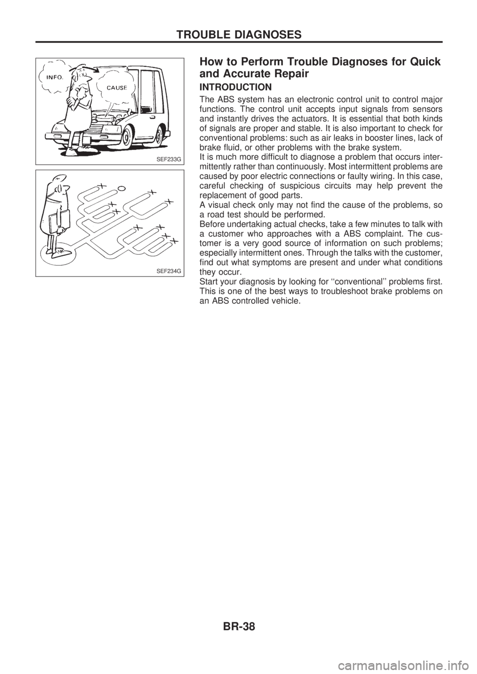
INTRODUCTION
The ABS system has an electronic control unit to control major
functions. The control unit accepts input signals from sensors
and instantly drives the actuators. It is essential that both kinds
of signals are proper and stable. It is also important to check for
conventional problems: such as air leaks in booster lines, lack of
brake fluid, or other problems with the brake system.
It is much more difficult to diagnose a problem that occurs inter-
mittently rather than continuously. Most intermittent problems are
caused by poor electric connections or faulty wiring. In this case,
careful checking of suspicious circuits may help prevent the
replacement of good parts.
A visual check only may not find the cause of the problems, so
a road test should be performed.
Before undertaking actual checks, take a few minutes to talk with
a customer who approaches with a ABS complaint. The cus-
tomer is a very good source of information on such problems;
especially intermittent ones. Through the talks with the customer,
find out what symptoms are present and under what conditions
they occur.
Start your diagnosis by looking for ``conventional'' problems first.
This is one of the best ways to troubleshoot brake problems on
an ABS controlled vehicle.
SEF233G
SEF234G
TROUBLE DIAGNOSES
BR-38
Page 65 of 1659
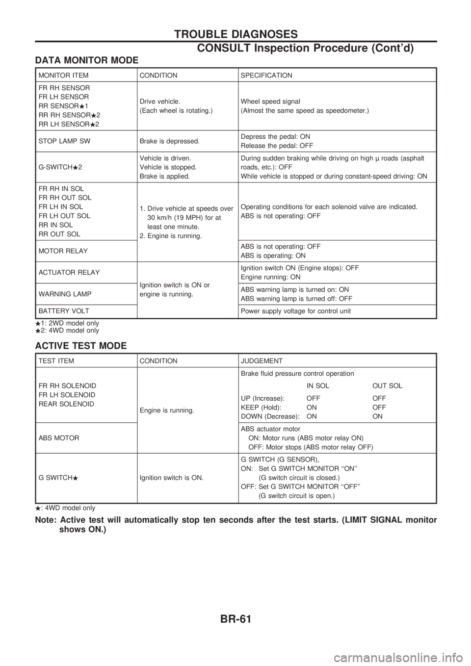
DATA MONITOR MODE
MONITOR ITEM CONDITION SPECIFICATION
FR RH SENSOR
FR LH SENSOR
RR SENSOR.1
RR RH SENSOR.2
RR LH SENSOR.2Drive vehicle.
(Each wheel is rotating.)Wheel speed signal
(Almost the same speed as speedometer.)
STOP LAMP SW Brake is depressed.Depress the pedal: ON
Release the pedal: OFF
G-SWITCH.2Vehicle is driven.
Vehicle is stopped.
Brake is applied.During sudden braking while driving on high roads (asphalt
roads, etc.): OFF
While vehicle is stopped or during constant-speed driving: ON
FR RH IN SOL
FR RH OUT SOL
FR LH IN SOL
FR LH OUT SOL
RR IN SOL
RR OUT SOL1. Drive vehicle at speeds over
30 km/h (19 MPH) for at
least one minute.
2. Engine is running.Operating conditions for each solenoid valve are indicated.
ABS is not operating: OFF
MOTOR RELAYABS is not operating: OFF
ABS is operating: ON
ACTUATOR RELAY
Ignition switch is ON or
engine is running.Ignition switch ON (Engine stops): OFF
Engine running: ON
WARNING LAMPABS warning lamp is turned on: ON
ABS warning lamp is turned off: OFF
BATTERY VOLT Power supply voltage for control unit
.1: 2WD model only
.2: 4WD model only
ACTIVE TEST MODE
TEST ITEM CONDITION JUDGEMENT
FR RH SOLENOID
FR LH SOLENOID
REAR SOLENOID
Engine is running.Brake fluid pressure control operation
IN SOL OUT SOL
UP (Increase):
KEEP (Hold):
DOWN (Decrease):OFF
ON
ONOFF
OFF
ON
ABS MOTORABS actuator motor
ON: Motor runs (ABS motor relay ON)
OFF: Motor stops (ABS motor relay OFF)
G SWITCH.Ignition switch is ON.G SWITCH (G SENSOR),
ON: Set G SWITCH MONITOR ``ON''
(G switch circuit is closed.)
OFF: Set G SWITCH MONITOR ``OFF''
(G switch circuit is open.)
.: 4WD model only
Note: Active test will automatically stop ten seconds after the test starts. (LIMIT SIGNAL monitor
shows ON.)
TROUBLE DIAGNOSES
CONSULT Inspection Procedure (Cont'd)
BR-61
Page 76 of 1659
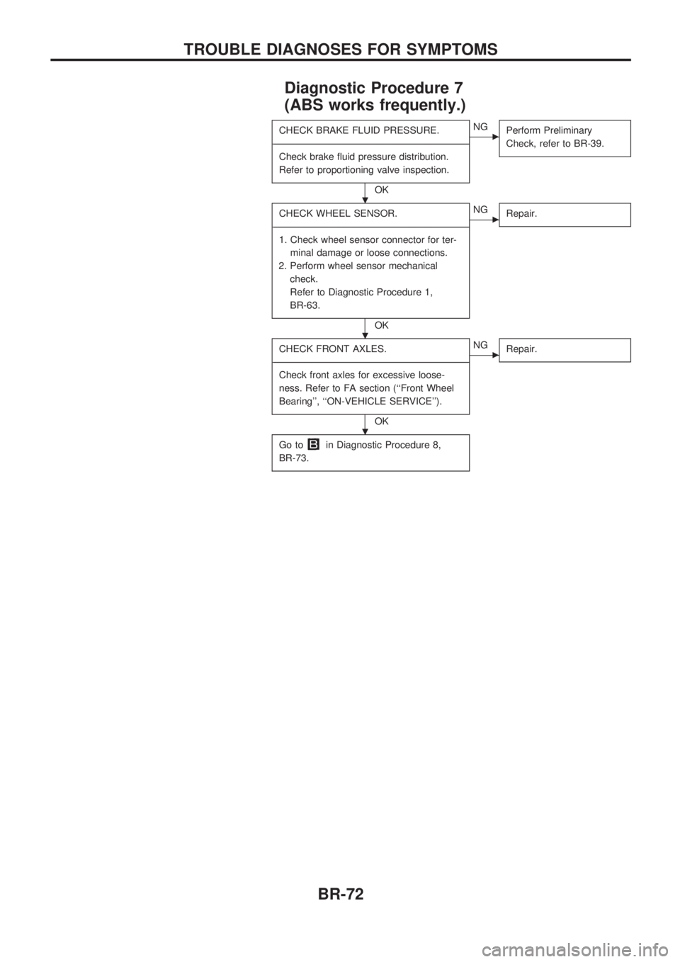
Diagnostic Procedure 7
(ABS works frequently.)
CHECK BRAKE FLUID PRESSURE.
-------------------------------------------------------------------------------------------------------------------------------------------------------------------------------------------------------------------------------------------------------------------------------------------------------------
Check brake fluid pressure distribution.
Refer to proportioning valve inspection.
OK
cNG
Perform Preliminary
Check, refer to BR-39.
CHECK WHEEL SENSOR.
-------------------------------------------------------------------------------------------------------------------------------------------------------------------------------------------------------------------------------------------------------------------------------------------------------------
1. Check wheel sensor connector for ter-
minal damage or loose connections.
2. Perform wheel sensor mechanical
check.
Refer to Diagnostic Procedure 1,
BR-63.
OK
cNG
Repair.
CHECK FRONT AXLES.
-------------------------------------------------------------------------------------------------------------------------------------------------------------------------------------------------------------------------------------------------------------------------------------------------------------
Check front axles for excessive loose-
ness. Refer to FA section (``Front Wheel
Bearing'', ``ON-VEHICLE SERVICE'').
OK
cNG
Repair.
Go toin Diagnostic Procedure 8,
BR-73.
.
.
.
TROUBLE DIAGNOSES FOR SYMPTOMS
BR-72