NISSAN PICK-UP 1999 Repair Manual
Manufacturer: NISSAN, Model Year: 1999, Model line: PICK-UP, Model: NISSAN PICK-UP 1999Pages: 666, PDF Size: 16.21 MB
Page 531 of 666
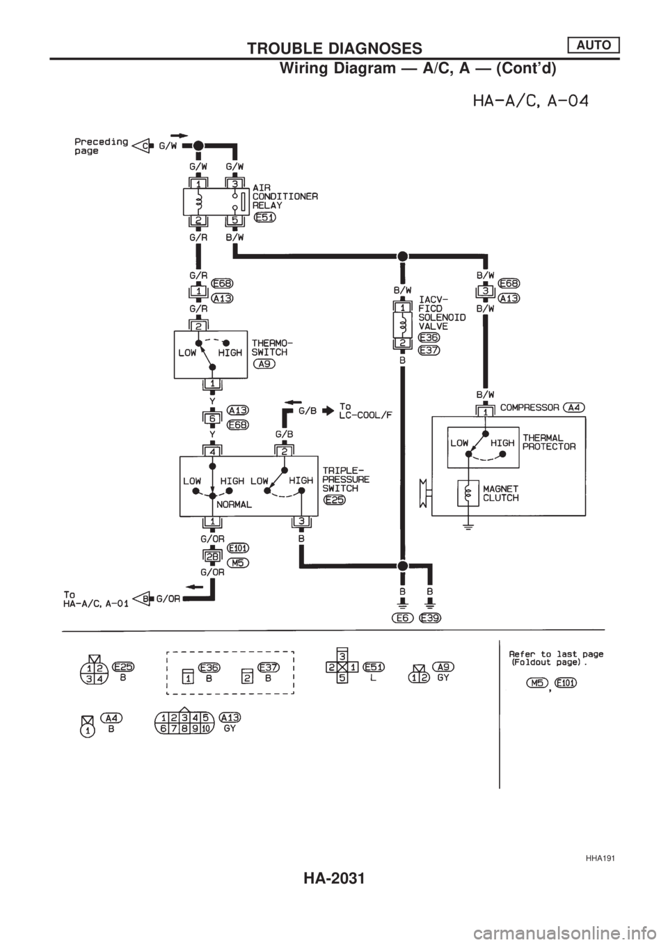
HHA191
TROUBLE DIAGNOSESAUTO
Wiring Diagram Ð A/C, A Ð (Cont'd)
HA-2031
Page 532 of 666
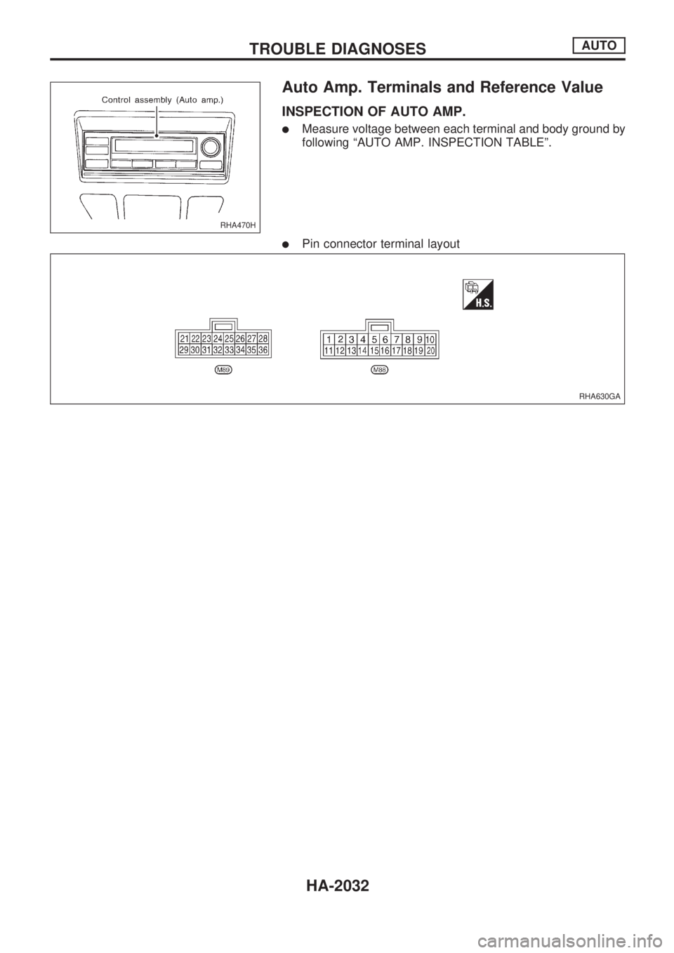
Auto Amp. Terminals and Reference Value
INSPECTION OF AUTO AMP.
lMeasure voltage between each terminal and body ground by
following ªAUTO AMP. INSPECTION TABLEº.
lPin connector terminal layout
RHA470H
RHA630GA
TROUBLE DIAGNOSESAUTO
HA-2032
Page 533 of 666
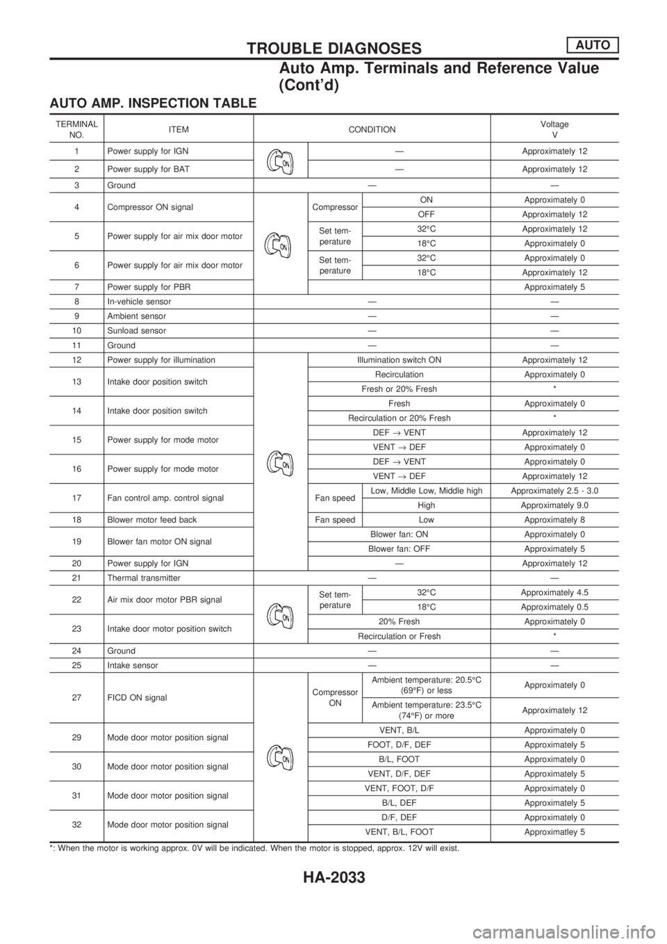
AUTO AMP. INSPECTION TABLE
TERMINAL
NO.ITEM CONDITIONVoltage
V
1 Power supply for IGN
Ð Approximately 12
2 Power supply for BAT Ð Approximately 12
3 Ground Ð Ð
4 Compressor ON signal
CompressorON Approximately 0
OFF Approximately 12
5 Power supply for air mix door motorSet tem-
perature32ÉC Approximately 12
18ÉC Approximately 0
6 Power supply for air mix door motorSet tem-
perature32ÉC Approximately 0
18ÉC Approximately 12
7 Power supply for PBRApproximately 5
8 In-vehicle sensor Ð Ð
9 Ambient sensor Ð Ð
10 Sunload sensor Ð Ð
11 Ground Ð Ð
12 Power supply for illumination
Illumination switch ON Approximately 12
13 Intake door position switchRecirculation Approximately 0
Fresh or 20% Fresh *
14 Intake door position switchFresh Approximately 0
Recirculation or 20% Fresh *
15 Power supply for mode motorDEF®VENT Approximately 12
VENT®DEF Approximately 0
16 Power supply for mode motorDEF®VENT Approximately 0
VENT®DEF Approximately 12
17 Fan control amp. control signal Fan speedLow, Middle Low, Middle high Approximately 2.5 - 3.0
High Approximately 9.0
18 Blower motor feed back Fan speed Low Approximately 8
19 Blower fan motor ON signalBlower fan: ON Approximately 0
Blower fan: OFF Approximately 5
20 Power supply for IGN Ð Approximately 12
21 Thermal transmitter Ð Ð
22 Air mix door motor PBR signal
Set tem-
perature32ÉC Approximately 4.5
18ÉC Approximately 0.5
23 Intake door motor position switch20% Fresh Approximately 0
Recirculation or Fresh *
24 Ground Ð Ð
25 Intake sensor Ð Ð
27 FICD ON signal
Compressor
ONAmbient temperature: 20.5ÉC
(69ÉF) or lessApproximately 0
Ambient temperature: 23.5ÉC
(74ÉF) or moreApproximately 12
29 Mode door motor position signalVENT, B/L Approximately 0
FOOT, D/F, DEF Approximately 5
30 Mode door motor position signalB/L, FOOT Approximately 0
VENT, D/F, DEF Approximately 5
31 Mode door motor position signalVENT, FOOT, D/F Approximately 0
B/L, DEF Approximately 5
32 Mode door motor position signalD/F, DEF Approximately 0
VENT, B/L, FOOT Approximatley 5
*: When the motor is working approx. 0V will be indicated. When the motor is stopped, approx. 12V will exist.
TROUBLE DIAGNOSESAUTO
Auto Amp. Terminals and Reference Value
(Cont'd)
HA-2033
Page 534 of 666
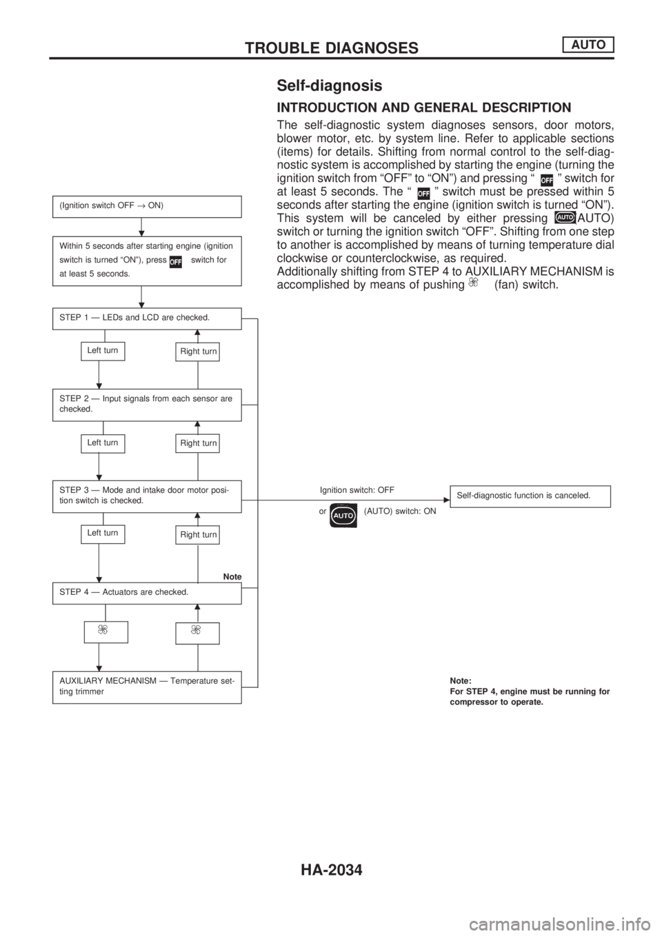
Self-diagnosis
INTRODUCTION AND GENERAL DESCRIPTION
The self-diagnostic system diagnoses sensors, door motors,
blower motor, etc. by system line. Refer to applicable sections
(items) for details. Shifting from normal control to the self-diag-
nostic system is accomplished by starting the engine (turning the
ignition switch from ªOFFº to ªONº) and pressing ª
º switch for
at least 5 seconds. The ª
º switch must be pressed within 5
seconds after starting the engine (ignition switch is turned ªONº).
This system will be canceled by either pressing
(AUTO)
switch or turning the ignition switch ªOFFº. Shifting from one step
to another is accomplished by means of turning temperature dial
clockwise or counterclockwise, as required.
Additionally shifting from STEP 4 to AUXILIARY MECHANISM is
accomplished by means of pushing
(fan) switch.
(Ignition switch OFF®ON)
Within 5 seconds after starting engine (ignition
switch is turned ªONº), press
switch for
at least 5 seconds.
STEP 1 Ð LEDs and LCD are checked.
m
Left turnRight turn
STEP 2 Ð Input signals from each sensor are
checked.
m
Left turnRight turn
STEP 3 Ð Mode and intake door motor posi-
tion switch is checked.Ignition switch: OFFc
or(AUTO) switch: ONSelf-diagnostic function is canceled.m
Left turnRight turn
Note
STEP 4 Ð Actuators are checked.
m
AUXILIARY MECHANISM Ð Temperature set-
ting trimmerNote:
For STEP 4, engine must be running for
compressor to operate.
.
.
.
.
.
.
TROUBLE DIAGNOSESAUTO
HA-2034
Page 535 of 666
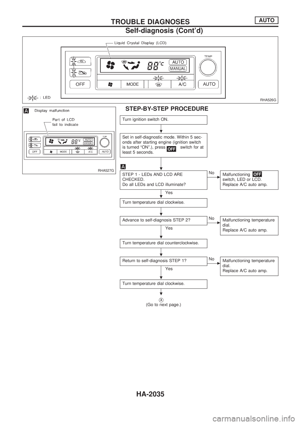
STEP-BY-STEP PROCEDURE
Turn ignition switch ON.
Set in self-diagnostic mode. Within 5 sec-
onds after starting engine (ignition switch
is turned ªONº.), press
switch for at
least 5 seconds.
STEP 1 - LEDs AND LCD ARE
CHECKED.
Do all LEDs and LCD illuminate?
Yes
cNo
Malfunctioning
switch, LED or LCD.
Replace A/C auto amp.
Turn temperature dial clockwise.
Advance to self-diagnosis STEP 2?
Yes
cNo
Malfunctioning temperature
dial.
Replace A/C auto amp.
Turn temperature dial counterclockwise.
Return to self-diagnosis STEP 1?
Yes
cNo
Malfunctioning temperature
dial.
Replace A/C auto amp.
Turn temperature dial clockwise.
VA(Go to next page.)
RHA526G
RHA527G
.
.
.
.
.
.
.
.
TROUBLE DIAGNOSESAUTO
Self-diagnosis (Cont'd)
HA-2035
Page 536 of 666
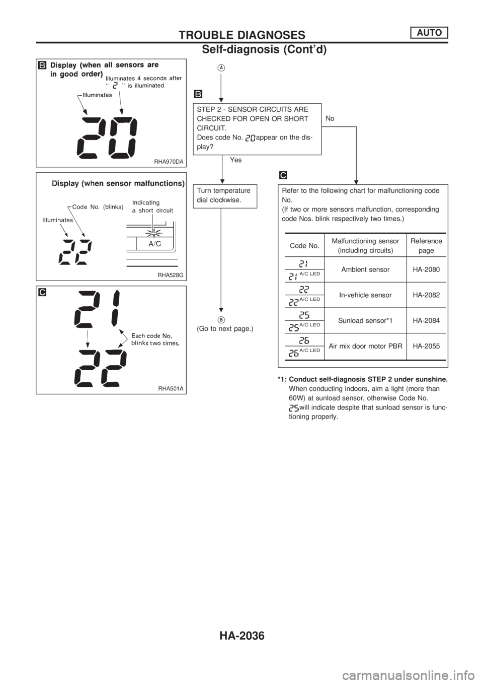
VA
STEP 2 - SENSOR CIRCUITS ARE
CHECKED FOR OPEN OR SHORT
CIRCUIT.
Does code No.
appear on the dis-
play?
YesNo
.
Turn temperature
dial clockwise.Refer to the following chart for malfunctioning code
No.
(If two or more sensors malfunction, corresponding
code Nos. blink respectively two times.)
*1: Conduct self-diagnosis STEP 2 under sunshine.
When conducting indoors, aim a light (more than
60W) at sunload sensor, otherwise Code No.
will indicate despite that sunload sensor is func-
tioning properly.
VB
(Go to next page.)
Code No.Malfunctioning sensor
(including circuits)Reference
page
Ambient sensor HA-2080A/C LED
In-vehicle sensor HA-2082A/C LED
Sunload sensor*1 HA-2084A/C LED
Air mix door motor PBR HA-2055A/C LED
RHA970DA
RHA528G
RHA501A
.
.
.
TROUBLE DIAGNOSESAUTO
Self-diagnosis (Cont'd)
HA-2036
Page 537 of 666

VB
STEP 3 - MODE DOOR POSITIONS
ARE CHECKED.
Does code No.
appear on the dis-
play?
YesNo
.
Turn temperature
dial clockwise.Mode door motor position switch is malfunctioning.
(If two or more mode doors are out of order, corre-
sponding code numbers blink respectively two
times.)
*1: If mode door motor harness connector is
disconnected, the following display pattern will
appear.
®
®®®®þ
VC
(Go to next page.)
Code
No.*1Mode door positionReference
page
VENT
HA-2049
B/L
FOOT
D/F
DEF
RHA869DC
RHA168DA
RHA498A
.
.
.
TROUBLE DIAGNOSESAUTO
Self-diagnosis (Cont'd)
HA-2037
Page 538 of 666
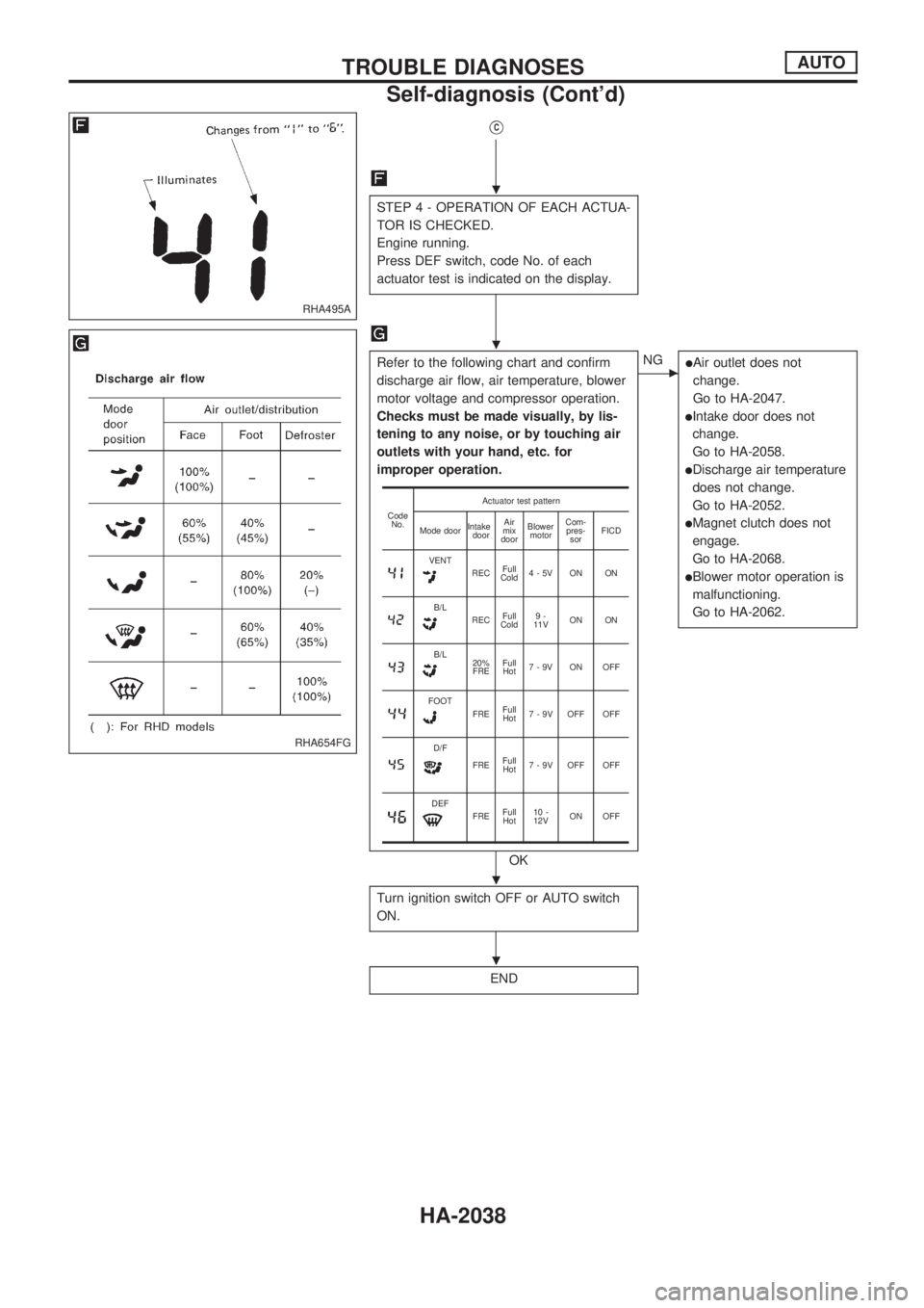
VC
STEP 4 - OPERATION OF EACH ACTUA-
TOR IS CHECKED.
Engine running.
Press DEF switch, code No. of each
actuator test is indicated on the display.
Refer to the following chart and confirm
discharge air flow, air temperature, blower
motor voltage and compressor operation.
Checks must be made visually, by lis-
tening to any noise, or by touching air
outlets with your hand, etc. for
improper operation.
OK
cNGlAir outlet does not
change.
Go to HA-2047.
lIntake door does not
change.
Go to HA-2058.
lDischarge air temperature
does not change.
Go to HA-2052.
lMagnet clutch does not
engage.
Go to HA-2068.
lBlower motor operation is
malfunctioning.
Go to HA-2062.
Turn ignition switch OFF or AUTO switch
ON.
END
Code
No.Actuator test pattern
Mode doorIntake
doorAir
mix
doorBlower
motorCom-
pres-
sorFICD
VENTRECFull
Cold4-5V ON ON
B/LRECFull
Cold9-
11VON ON
B/L20%
FREFull
Hot7-9V ON OFF
FOOTFREFull
Hot7 - 9V OFF OFF
D/F
FREFull
Hot7 - 9V OFF OFF
DEFFREFull
Hot10 -
12VON OFF
RHA495A
RHA654FG
.
.
.
.
TROUBLE DIAGNOSESAUTO
Self-diagnosis (Cont'd)
HA-2038
Page 539 of 666
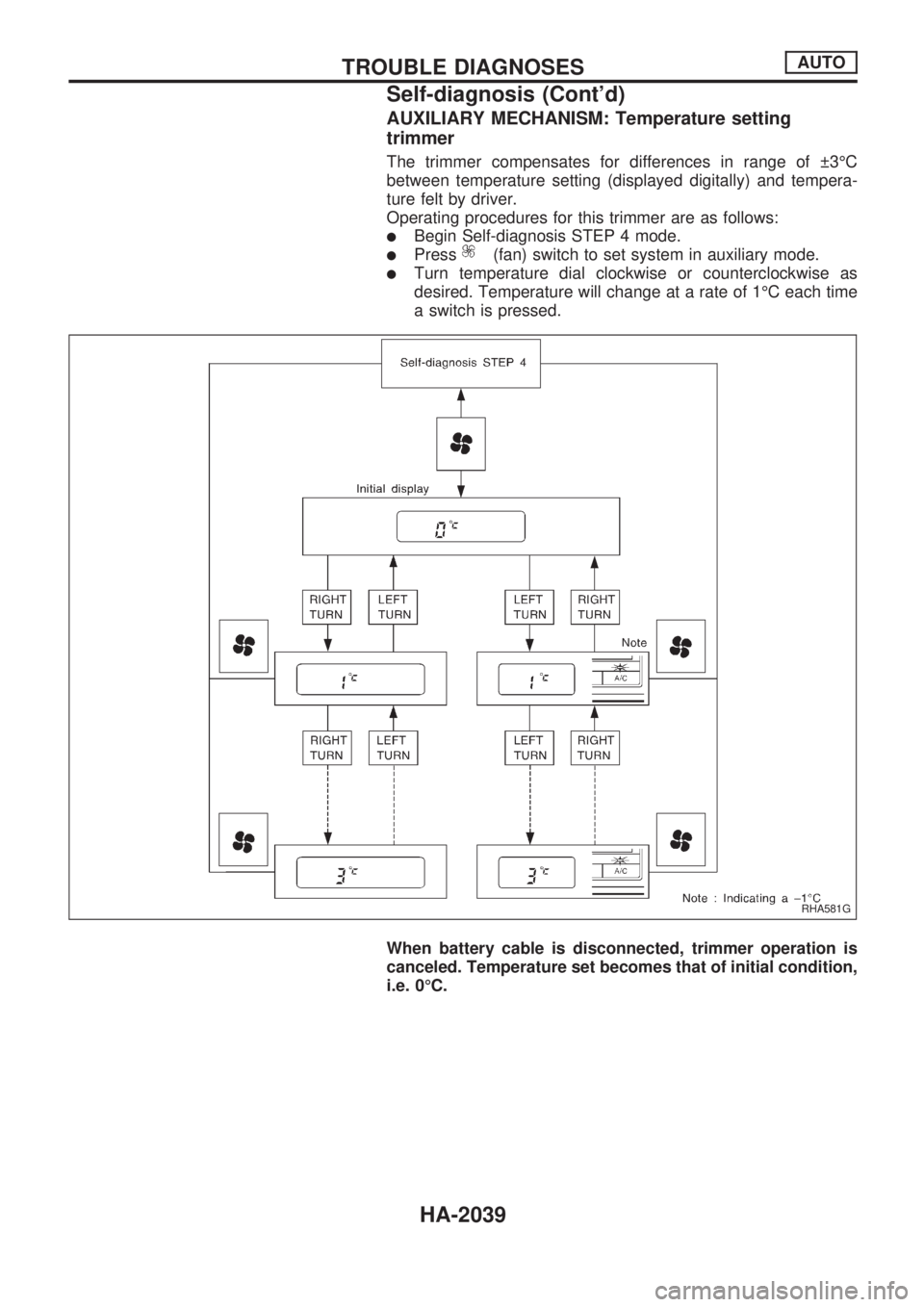
AUXILIARY MECHANISM: Temperature setting
trimmer
The trimmer compensates for differences in range of 3ÉC
between temperature setting (displayed digitally) and tempera-
ture felt by driver.
Operating procedures for this trimmer are as follows:
lBegin Self-diagnosis STEP 4 mode.
lPress(fan) switch to set system in auxiliary mode.
lTurn temperature dial clockwise or counterclockwise as
desired. Temperature will change at a rate of 1ÉC each time
a switch is pressed.
When battery cable is disconnected, trimmer operation is
canceled. Temperature set becomes that of initial condition,
i.e. 0ÉC.
RHA581G
TROUBLE DIAGNOSESAUTO
Self-diagnosis (Cont'd)
HA-2039
Page 540 of 666
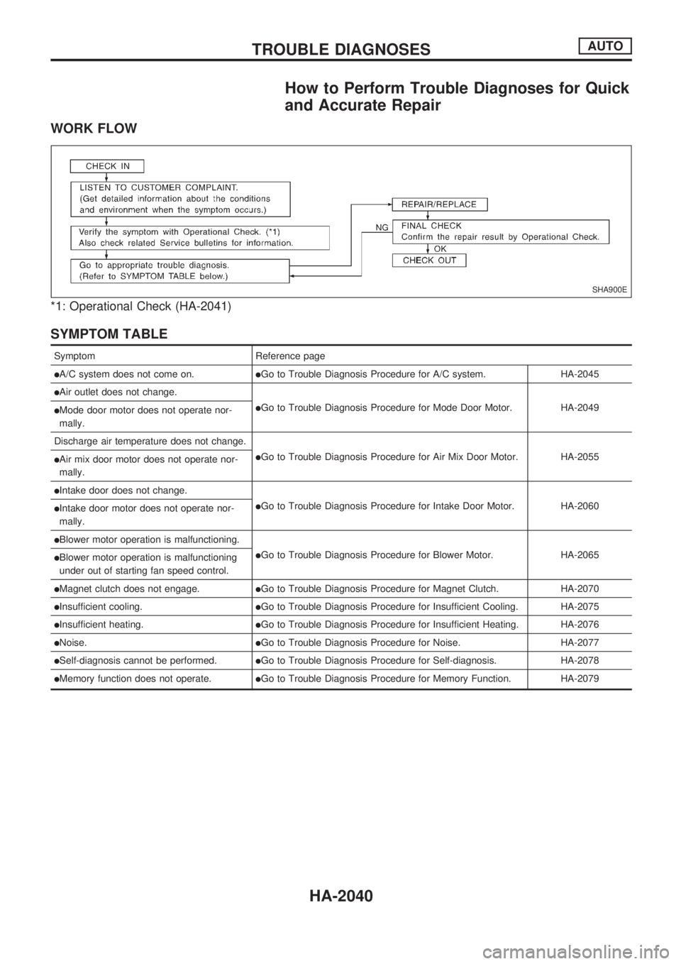
How to Perform Trouble Diagnoses for Quick
and Accurate Repair
WORK FLOW
*1: Operational Check (HA-2041)
SYMPTOM TABLE
Symptom Reference page
lA/C system does not come on.lGo to Trouble Diagnosis Procedure for A/C system. HA-2045
lAir outlet does not change.
lGo to Trouble Diagnosis Procedure for Mode Door Motor. HA-2049lMode door motor does not operate nor-
mally.
Discharge air temperature does not change.
lGo to Trouble Diagnosis Procedure for Air Mix Door Motor. HA-2055lAir mix door motor does not operate nor-
mally.
lIntake door does not change.
lGo to Trouble Diagnosis Procedure for Intake Door Motor. HA-2060lIntake door motor does not operate nor-
mally.
lBlower motor operation is malfunctioning.
lGo to Trouble Diagnosis Procedure for Blower Motor. HA-2065lBlower motor operation is malfunctioning
under out of starting fan speed control.
lMagnet clutch does not engage.lGo to Trouble Diagnosis Procedure for Magnet Clutch. HA-2070
lInsufficient cooling.lGo to Trouble Diagnosis Procedure for Insufficient Cooling. HA-2075
lInsufficient heating.lGo to Trouble Diagnosis Procedure for Insufficient Heating. HA-2076
lNoise.lGo to Trouble Diagnosis Procedure for Noise. HA-2077
lSelf-diagnosis cannot be performed.lGo to Trouble Diagnosis Procedure for Self-diagnosis. HA-2078
lMemory function does not operate.lGo to Trouble Diagnosis Procedure for Memory Function. HA-2079
SHA900E
TROUBLE DIAGNOSESAUTO
HA-2040