NISSAN PICK-UP 1999 Repair Manual
Manufacturer: NISSAN, Model Year: 1999, Model line: PICK-UP, Model: NISSAN PICK-UP 1999Pages: 666, PDF Size: 16.21 MB
Page 581 of 666
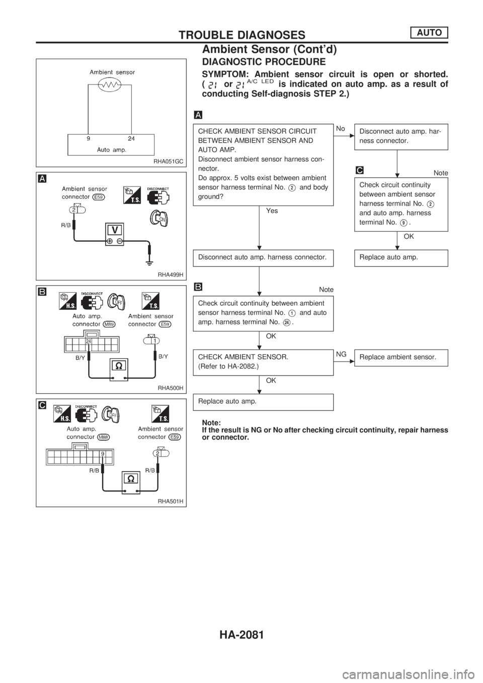
DIAGNOSTIC PROCEDURE
SYMPTOM: Ambient sensor circuit is open or shorted.
(
orA/C LEDis indicated on auto amp. as a result of
conducting Self-diagnosis STEP 2.)
CHECK AMBIENT SENSOR CIRCUIT
BETWEEN AMBIENT SENSOR AND
AUTO AMP.
Disconnect ambient sensor harness con-
nector.
Do approx. 5 volts exist between ambient
sensor harness terminal No.
V2and body
ground?
Yes
cNo
Disconnect auto amp. har-
ness connector.
Note
Check circuit continuity
between ambient sensor
harness terminal No.
V2
and auto amp. harness
terminal No.
V9.
OK
Disconnect auto amp. harness connector.
Replace auto amp.
Note
Check circuit continuity between ambient
sensor harness terminal No.
V1and auto
amp. harness terminal No.
V24.
OK
CHECK AMBIENT SENSOR.
(Refer to HA-2082.)
OK
cNG
Replace ambient sensor.
Replace auto amp.
Note:
If the result is NG or No after checking circuit continuity, repair harness
or connector.
RHA051GC
RHA499H
RHA500H
RHA501H
.
..
.
.
.
TROUBLE DIAGNOSESAUTO
Ambient Sensor (Cont'd)
HA-2081
Page 582 of 666
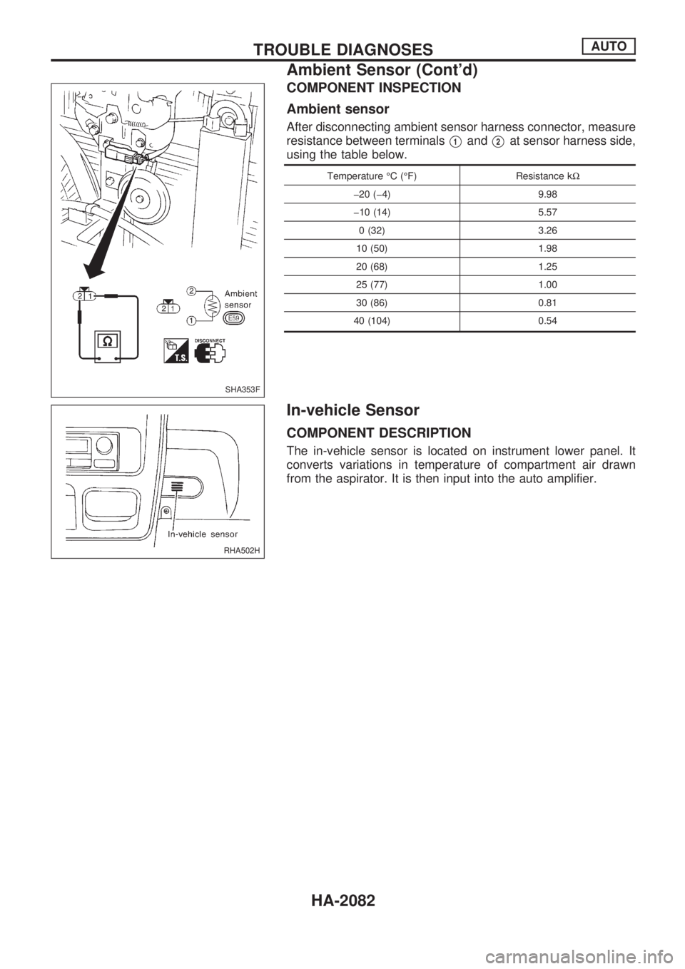
COMPONENT INSPECTION
Ambient sensor
After disconnecting ambient sensor harness connector, measure
resistance between terminals
V1andV2at sensor harness side,
using the table below.
Temperature ÉC (ÉF) Resistance kW
þ20 (þ4) 9.98
þ10 (14) 5.57
0 (32) 3.26
10 (50) 1.98
20 (68) 1.25
25 (77) 1.00
30 (86) 0.81
40 (104) 0.54
In-vehicle Sensor
COMPONENT DESCRIPTION
The in-vehicle sensor is located on instrument lower panel. It
converts variations in temperature of compartment air drawn
from the aspirator. It is then input into the auto amplifier.
SHA353F
RHA502H
TROUBLE DIAGNOSESAUTO
Ambient Sensor (Cont'd)
HA-2082
Page 583 of 666
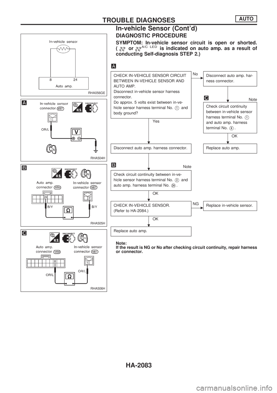
DIAGNOSTIC PROCEDURE
SYMPTOM: In-vehicle sensor circuit is open or shorted.
(
orA/C LEDis indicated on auto amp. as a result of
conducting Self-diagnosis STEP 2.)
CHECK IN-VEHICLE SENSOR CIRCUIT
BETWEEN IN-VEHICLE SENSOR AND
AUTO AMP.
Disconnect in-vehicle sensor harness
connector.
Do approx. 5 volts exist between in-ve-
hicle sensor harness terminal No.
V1and
body ground?
Yes
cNo
Disconnect auto amp. har-
ness connector.
Note
Check circuit continuity
between in-vehicle sensor
harness terminal No.
V1
and auto amp. harness
terminal No.
V8.
OK
Disconnect auto amp. harness connector.
Replace auto amp.
Note
Check circuit continuity between in-ve-
hicle sensor harness terminal No.
V2and
auto amp. harness terminal No.
V24.
OK
CHECK IN-VEHICLE SENSOR.
(Refer to HA-2084.)
OK
cNG
Replace in-vehicle sensor.
Replace auto amp.
Note:
If the result is NG or No after checking circuit continuity, repair harness
or connector.
RHA056GE
RHA504H
RHA505H
RHA506H
.
..
.
.
.
TROUBLE DIAGNOSESAUTO
In-vehicle Sensor (Cont'd)
HA-2083
Page 584 of 666
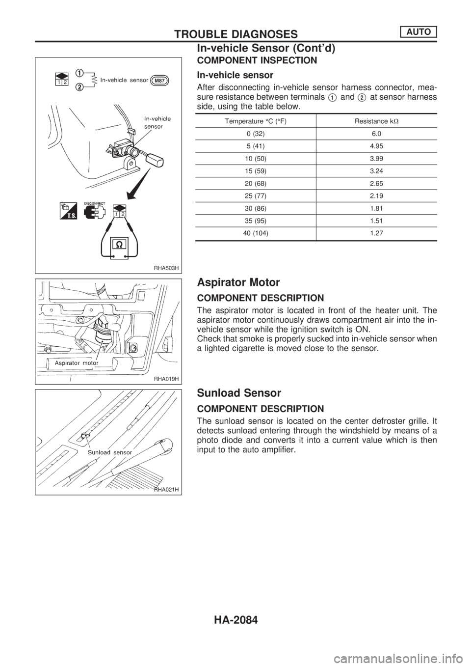
COMPONENT INSPECTION
In-vehicle sensor
After disconnecting in-vehicle sensor harness connector, mea-
sure resistance between terminals
V1andV2at sensor harness
side, using the table below.
Temperature ÉC (ÉF) Resistance kW
0 (32) 6.0
5 (41) 4.95
10 (50) 3.99
15 (59) 3.24
20 (68) 2.65
25 (77) 2.19
30 (86) 1.81
35 (95) 1.51
40 (104) 1.27
Aspirator Motor
COMPONENT DESCRIPTION
The aspirator motor is located in front of the heater unit. The
aspirator motor continuously draws compartment air into the in-
vehicle sensor while the ignition switch is ON.
Check that smoke is properly sucked into in-vehicle sensor when
a lighted cigarette is moved close to the sensor.
Sunload Sensor
COMPONENT DESCRIPTION
The sunload sensor is located on the center defroster grille. It
detects sunload entering through the windshield by means of a
photo diode and converts it into a current value which is then
input to the auto amplifier.
RHA503H
RHA019H
RHA021H
TROUBLE DIAGNOSESAUTO
In-vehicle Sensor (Cont'd)
HA-2084
Page 585 of 666
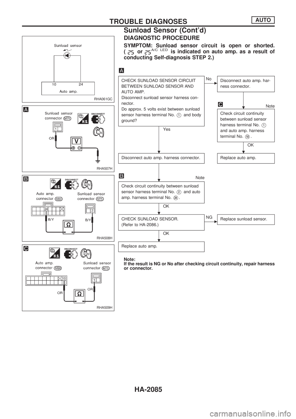
DIAGNOSTIC PROCEDURE
SYMPTOM: Sunload sensor circuit is open or shorted.
(
orA/C LEDis indicated on auto amp. as a result of
conducting Self-diagnosis STEP 2.)
CHECK SUNLOAD SENSOR CIRCUIT
BETWEEN SUNLOAD SENSOR AND
AUTO AMP.
Disconnect sunload sensor harness con-
nector.
Do approx. 5 volts exist between sunload
sensor harness terminal No.
V1and body
ground?
Yes
cNo
Disconnect auto amp. har-
ness connector.
Note
Check circuit continuity
between sunload sensor
harness terminal No.
V1
and auto amp. harness
terminal No.
V10.
OK
Disconnect auto amp. harness connector.
Replace auto amp.
Note
Check circuit continuity between sunload
sensor harness terminal No.
V2and auto
amp. harness terminal No.
V24.
OK
CHECK SUNLOAD SENSOR.
(Refer to HA-2086.)
OK
cNG
Replace sunload sensor.
Replace auto amp.
Note:
If the result is NG or No after checking circuit continuity, repair harness
or connector.
RHA061GC
RHA507H
RHA508H
RHA509H
.
..
.
.
.
TROUBLE DIAGNOSESAUTO
Sunload Sensor (Cont'd)
HA-2085
Page 586 of 666
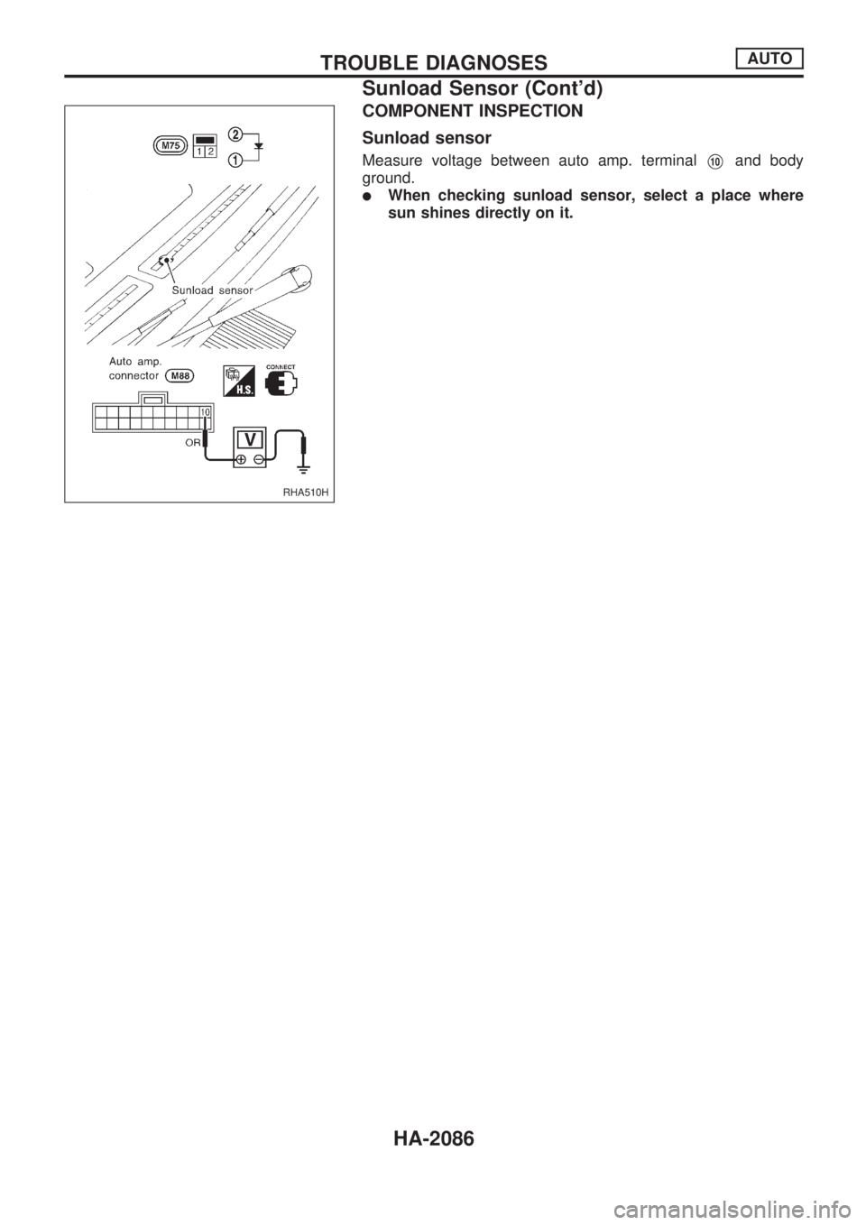
COMPONENT INSPECTION
Sunload sensor
Measure voltage between auto amp. terminalV10and body
ground.
lWhen checking sunload sensor, select a place where
sun shines directly on it.
RHA510H
TROUBLE DIAGNOSESAUTO
Sunload Sensor (Cont'd)
HA-2086
Page 587 of 666
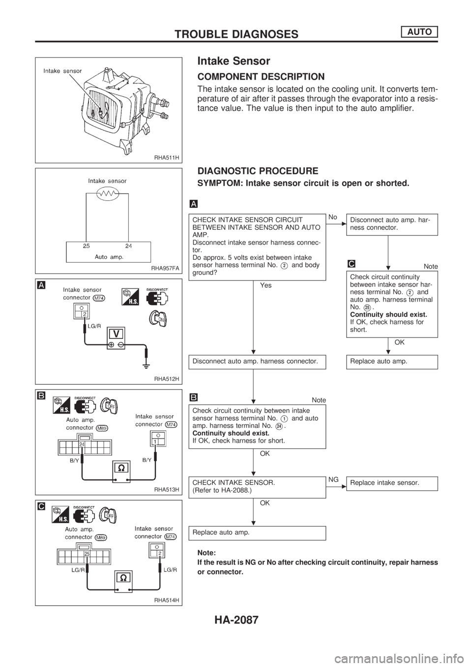
Intake Sensor
COMPONENT DESCRIPTION
The intake sensor is located on the cooling unit. It converts tem-
perature of air after it passes through the evaporator into a resis-
tance value. The value is then input to the auto amplifier.
DIAGNOSTIC PROCEDURE
SYMPTOM: Intake sensor circuit is open or shorted.
CHECK INTAKE SENSOR CIRCUIT
BETWEEN INTAKE SENSOR AND AUTO
AMP.
Disconnect intake sensor harness connec-
tor.
Do approx. 5 volts exist between intake
sensor harness terminal No.
V2and body
ground?
Yes
cNo
Disconnect auto amp. har-
ness connector.
Note
Check circuit continuity
between intake sensor har-
ness terminal No.
V2and
auto amp. harness terminal
No.
V25.
Continuity should exist.
If OK, check harness for
short.
OK
Disconnect auto amp. harness connector.
Replace auto amp.
Note
Check circuit continuity between intake
sensor harness terminal No.
V1and auto
amp. harness terminal No.
V24.
Continuity should exist.
If OK, check harness for short.
OK
CHECK INTAKE SENSOR.
(Refer to HA-2088.)
OK
cNG
Replace intake sensor.
Replace auto amp.
Note:
If the result is NG or No after checking circuit continuity, repair harness
or connector.
RHA511H
RHA957FA
RHA512H
RHA513H
RHA514H
.
..
.
.
.
TROUBLE DIAGNOSESAUTO
HA-2087
Page 588 of 666
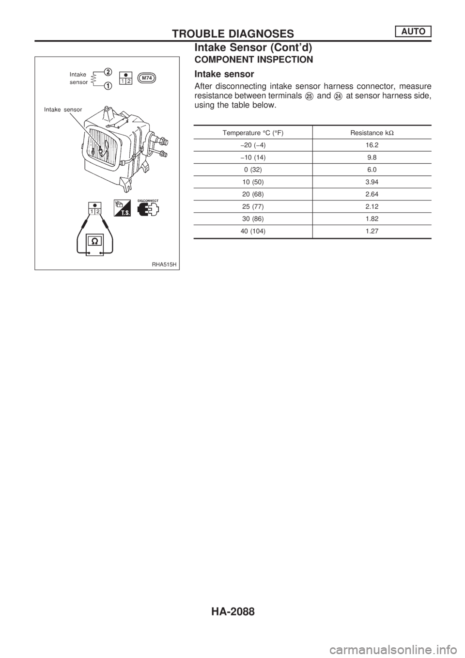
COMPONENT INSPECTION
Intake sensor
After disconnecting intake sensor harness connector, measure
resistance between terminals
V25andV24at sensor harness side,
using the table below.
Temperature ÉC (ÉF) Resistance kW
þ20 (þ4) 16.2
þ10 (14) 9.8
0 (32) 6.0
10 (50) 3.94
20 (68) 2.64
25 (77) 2.12
30 (86) 1.82
40 (104) 1.27
RHA515H
TROUBLE DIAGNOSESAUTO
Intake Sensor (Cont'd)
HA-2088
Page 589 of 666

ALPHABETICAL INDEX
SECTION
IDX
IDX
Page 590 of 666
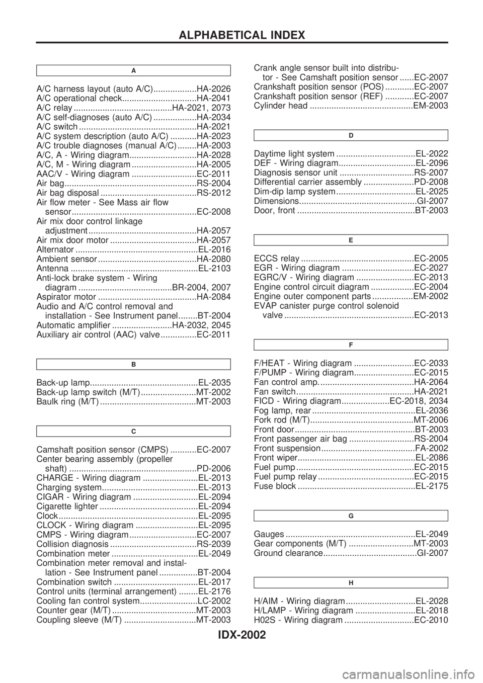
A
A/C harness layout (auto A/C)..................HA-2026
A/C operational check...............................HA-2041
A/C relay .........................................HA-2021, 2073
A/C self-diagnoses (auto A/C) ..................HA-2034
A/C switch .................................................HA-2021
A/C system description (auto A/C) ...........HA-2023
A/C trouble diagnoses (manual A/C) ........HA-2003
A/C, A - Wiring diagram............................HA-2028
A/C, M - Wiring diagram ...........................HA-2005
AAC/V - Wiring diagram ...........................EC-2011
Air bag.......................................................RS-2004
Air bag disposal ........................................RS-2012
Air flow meter - See Mass air flow
sensor....................................................EC-2008
Air mix door control linkage
adjustment .............................................HA-2057
Air mix door motor ....................................HA-2057
Alternator ...................................................EL-2016
Ambient sensor .........................................HA-2080
Antenna .....................................................EL-2103
Anti-lock brake system - Wiring
diagram .......................................BR-2004, 2007
Aspirator motor .........................................HA-2084
Audio and A/C control removal and
installation - See Instrument panel........BT-2004
Automatic amplifier .........................HA-2032, 2045
Auxiliary air control (AAC) valve ...............EC-2011
B
Back-up lamp.............................................EL-2035
Back-up lamp switch (M/T) .......................MT-2002
Baulk ring (M/T) ........................................MT-2003
C
Camshaft position sensor (CMPS) ...........EC-2007
Center bearing assembly (propeller
shaft) .....................................................PD-2006
CHARGE - Wiring diagram .......................EL-2013
Charging system........................................EL-2013
CIGAR - Wiring diagram ...........................EL-2094
Cigarette lighter .........................................EL-2094
Clock ..........................................................EL-2095
CLOCK - Wiring diagram ..........................EL-2095
CMPS - Wiring diagram ............................EC-2007
Collision diagnosis ....................................RS-2039
Combination meter ....................................EL-2049
Combination meter removal and instal-
lation - See Instrument panel ................BT-2004
Combination switch ...................................EL-2017
Control units (terminal arrangement) ........EL-2176
Cooling fan control system........................LC-2002
Counter gear (M/T) ...................................MT-2003
Coupling sleeve (M/T) ..............................MT-2003Crank angle sensor built into distribu-
tor - See Camshaft position sensor ......EC-2007
Crankshaft position sensor (POS) ............EC-2007
Crankshaft position sensor (REF) ............EC-2007
Cylinder head ...........................................EM-2003
D
Daytime light system .................................EL-2022
DEF - Wiring diagram................................EL-2096
Diagnosis sensor unit ...............................RS-2007
Differential carrier assembly .....................PD-2008
Dim-dip lamp system .................................EL-2025
Dimensions.................................................GI-2007
Door, front .................................................BT-2003
E
ECCS relay ...............................................EC-2005
EGR - Wiring diagram ..............................EC-2027
EGRC/V - Wiring diagram ........................EC-2013
Engine control circuit diagram ..................EC-2004
Engine outer component parts .................EM-2002
EVAP canister purge control solenoid
valve ......................................................EC-2013
F
F/HEAT - Wiring diagram .........................EC-2033
F/PUMP - Wiring diagram.........................EC-2015
Fan control amp. .......................................HA-2064
Fan switch .................................................HA-2021
FICD - Wiring diagram....................EC-2018, 2034
Fog lamp, rear ...........................................EL-2036
Fork rod (M/T)...........................................MT-2006
Front door ..................................................BT-2003
Front passenger air bag ...........................RS-2004
Front suspension .......................................FA-2002
Front wiper.................................................EL-2086
Fuel pump .................................................EC-2015
Fuel pump relay ........................................EC-2015
Fuse block .................................................EL-2175
G
Gauges ......................................................EL-2049
Gear components (M/T) ...........................MT-2003
Ground clearance.......................................GI-2007
H
H/AIM - Wiring diagram .............................EL-2028
H/LAMP - Wiring diagram .........................EL-2018
H02S - Wiring diagram .............................EC-2010
ALPHABETICAL INDEX
IDX-2002