NISSAN PICK-UP 1999 Repair Manual
Manufacturer: NISSAN, Model Year: 1999, Model line: PICK-UP, Model: NISSAN PICK-UP 1999Pages: 666, PDF Size: 16.21 MB
Page 591 of 666
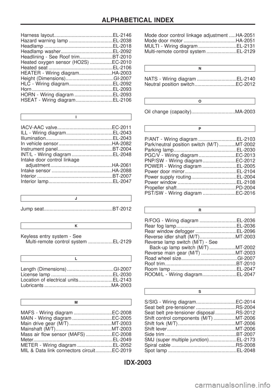
Harness layout...........................................EL-2146
Hazard warning lamp ................................EL-2038
Headlamp ..................................................EL-2018
Headlamp washer......................................EL-2092
Headlining - See Roof trim........................BT-2010
Heated oxygen sensor (HO2S) ................EC-2010
Heated seat ...............................................EL-2106
HEATER - Wiring diagram........................HA-2003
Height (Dimensions)...................................GI-2007
HLC - Wiring diagram................................EL-2092
Horn ...........................................................EL-2093
HORN - Wiring diagram ............................EL-2093
HSEAT - Wiring diagram ...........................EL-2106
I
IACV-AAC valve........................................EC-2011
ILL - Wiring diagram ..................................EL-2043
Illumination.................................................EL-2043
In vehicle sensor .......................................HA-2082
Instrument panel........................................BT-2004
INT/L - Wiring diagram ..............................EL-2048
Intake door control linkage
adjustment .............................................HA-2061
Intake sensor ............................................HA-2088
Interior .......................................................BT-2007
Interior lamp...............................................EL-2047
J
Jump seat ..................................................BT-2012
K
Keyless entry system - See
Multi-remote control system ..................EL-2129
L
Length (Dimensions) ..................................GI-2007
License lamp .............................................EL-2030
Location of electrical units .........................EL-2143
Lubricants .................................................MA-2003
M
MAFS - Wiring diagram ............................EC-2008
MAIN - Wiring diagram .............................EC-2005
Main drive gear (M/T) ...............................MT-2003
Mainshaft (M/T).........................................MT-2003
Mass air flow sensor (MAFS) ...................EC-2008
Meter..........................................................EL-2049
METER - Wiring diagram ..........................EL-2052
MIL & Data link connectors circuit ............EC-2019Mode door control linkage adjustment .....HA-2051
Mode door motor ......................................HA-2051
MULTI - Wiring diagram ............................EL-2131
Multi-remote control system ......................EL-2129
N
NATS - Wiring diagram .............................EL-2140
Neutral position switch ..............................EC-2012
O
Oil change (capacity)................................MA-2003
P
P/ANT - Wiring diagram ............................EL-2103
Park/neutral position switch (M/T) ............MT-2002
Parking lamp..............................................EL-2030
PGC/V - Wiring diagram ...........................EC-2013
PNP/SW - Wiring diagram ........................EC-2012
POWER - Wiring diagram .........................EL-2005
Power door mirror......................................EL-2104
Power supply routing .................................EL-2004
Power window ...........................................EL-2108
Propeller shaft ...........................................PD-2004
PST/SW - Wiring diagram ........................EC-2016
R
R/FOG - Wiring diagram ...........................EL-2036
Rear fog lamp ............................................EL-2036
Rear window defogger ..............................EL-2096
Reverse idler shaft (M/T) ..........................MT-2003
Reverse lamp switch (M/T) - See
Back-up lamp switch (M/T) ...................MT-2002
Reverse main gear (M/T) .........................MT-2003
Road wheel size.........................................GI-2007
Roof trim ....................................................BT-2010
Room lamp ................................................EL-2047
ROOM/L - Wiring diagram.........................EL-2047
S
S/SIG - Wiring diagram.............................EC-2014
Seat belt pre-tensioner .............................RS-2004
Seat belt pre-tensioner disposal ...............RS-2012
Shift control components (M/T) ................MT-2006
Shift fork (M/T) ..........................................MT-2006
Shift lever ..................................................MT-2006
Side trim ....................................................BT-2007
SMJ (super multiple junction) ....................EL-2173
Spiral cable ...............................................RS-2008
Spot lamp ..................................................EL-2048
ALPHABETICAL INDEX
IDX-2003
Page 592 of 666
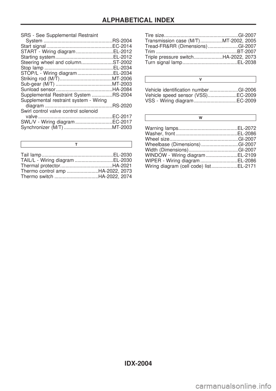
SRS - See Supplemental Restraint
System ..................................................RS-2004
Start signal ................................................EC-2014
START - Wiring diagram ...........................EL-2012
Starting system ..........................................EL-2012
Steering wheel and column.......................ST-2002
Stop lamp ..................................................EL-2034
STOP/L - Wiring diagram ..........................EL-2034
Striking rod (M/T) ......................................MT-2006
Sub-gear (M/T) .........................................MT-2003
Sunload sensor .........................................HA-2084
Supplemental Restraint System ...............RS-2004
Supplemental restraint system - Wiring
diagram .................................................RS-2020
Swirl control valve control solenoid
valve ......................................................EC-2017
SWL/V - Wiring diagram ...........................EC-2017
Synchronizer (M/T) ...................................MT-2003
T
Tail lamp ....................................................EL-2030
TAIL/L - Wiring diagram ............................EL-2030
Thermal protector......................................HA-2021
Thermo control amp .......................HA-2022, 2073
Thermo switch ................................HA-2022, 2074Tire size......................................................GI-2007
Transmission case (M/T) ................MT-2002, 2005
Tread-FR&RR (Dimensions) ......................GI-2007
Trim ...........................................................BT-2007
Triple pressure switch.....................HA-2022, 2073
Turn signal lamp ........................................EL-2038
V
Vehicle identification number .....................GI-2006
Vehicle speed sensor (VSS).....................EC-2009
VSS - Wiring diagram ...............................EC-2009
W
Warning lamps...........................................EL-2072
Washer, front .............................................EL-2086
Wheel size..................................................GI-2007
Wheelbase (Dimensions) ...........................GI-2007
Width (Dimensions) ....................................GI-2007
WINDOW - Wiring diagram .......................EL-2109
WIPER - Wiring diagram ...........................EL-2086
Wiring diagram (cell code) list ...................EL-2171
ALPHABETICAL INDEX
IDX-2004
Page 593 of 666
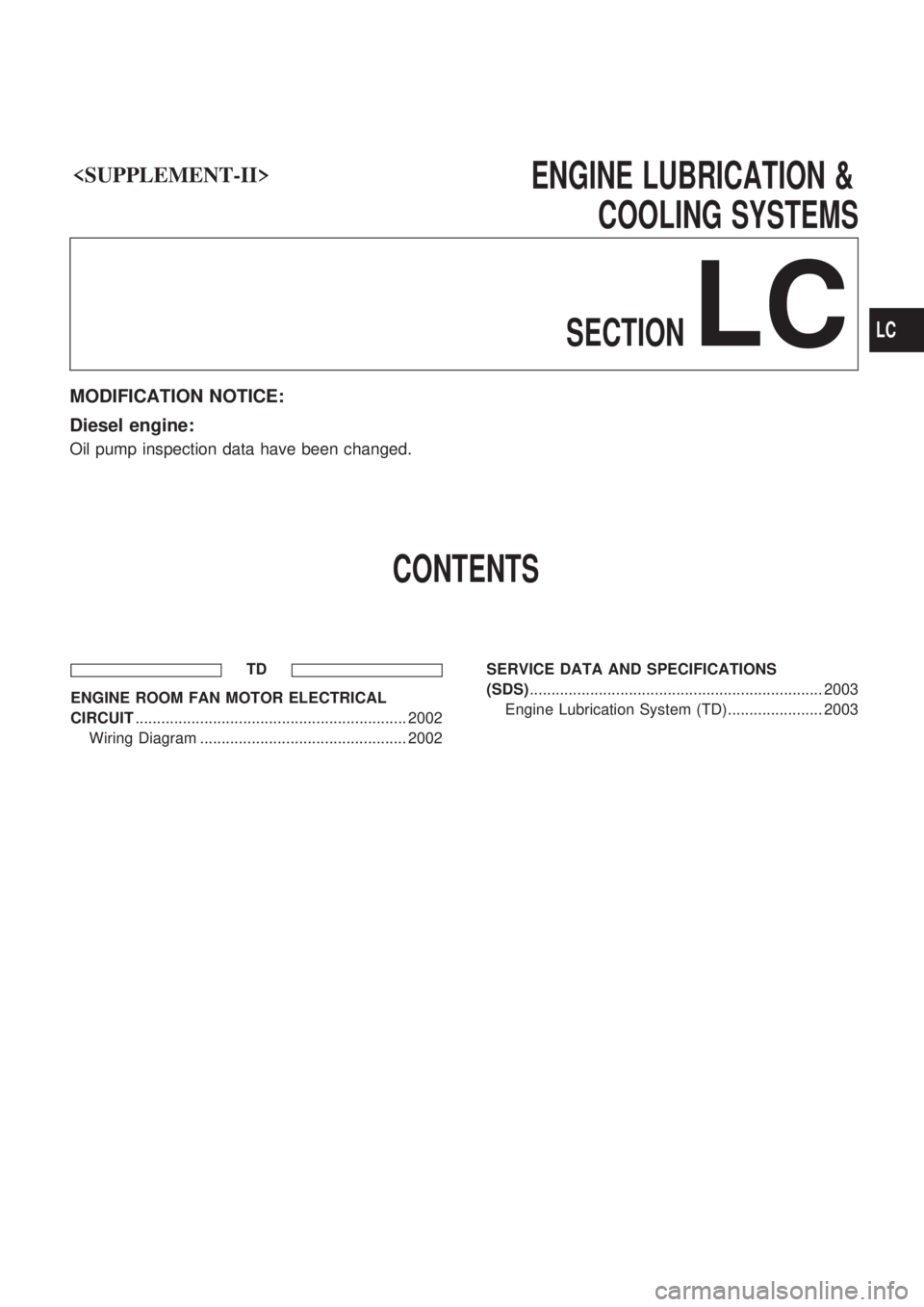
COOLING SYSTEMS
SECTION
LC
MODIFICATION NOTICE:
Diesel engine:
Oil pump inspection data have been changed.
CONTENTS
TD
ENGINE ROOM FAN MOTOR ELECTRICAL
CIRCUIT ............................................................... 2002
Wiring Diagram ................................................ 2002 SERVICE DATA AND SPECIFICATIONS
(SDS)
.................................................................... 2003
Engine Lubrication System (TD)...................... 2003
LC
Page 594 of 666
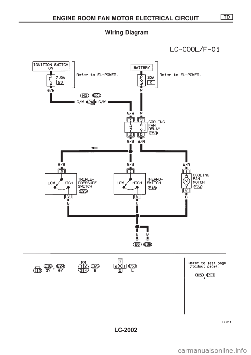
Wiring Diagram
HLC011
ENGINE ROOM FAN MOTOR ELECTRICAL CIRCUITTD
LC-2002
Page 595 of 666
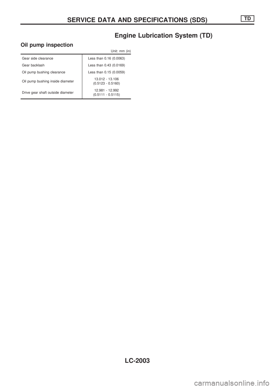
Engine Lubrication System (TD)
Oil pump inspection
Unit: mm (in)
Gear side clearance Less than 0.16 (0.0063)
Gear backlash Less than 0.43 (0.0169)
Oil pump bushing clearance Less than 0.15 (0.0059)
Oil pump bushing inside diameter13.012 - 13.106
(0.5123 - 0.5160)
Drive gear shaft outside diameter12.981 - 12.992
(0.5111 - 0.5115)
SERVICE DATA AND SPECIFICATIONS (SDS)TD
LC-2003
Page 596 of 666
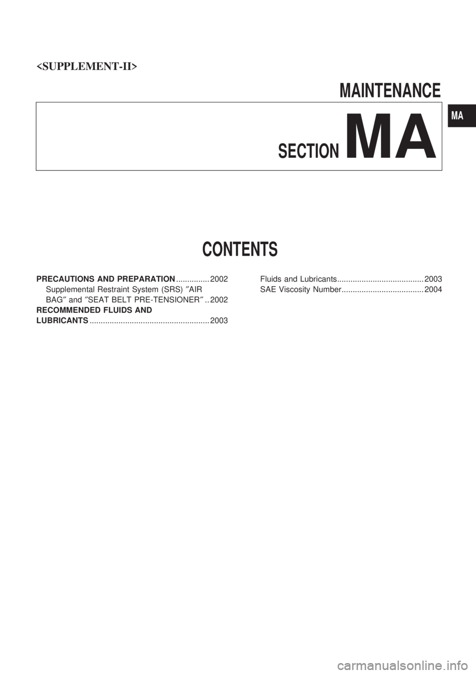
MAINTENANCE
SECTION
MA
CONTENTS
PRECAUTIONS AND PREPARATION ............... 2002
Supplemental Restraint System (SRS) ²AIR
BAG ²and ²SEAT BELT PRE-TENSIONER ².. 2002
RECOMMENDED FLUIDS AND
LUBRICANTS ...................................................... 2003 Fluids and Lubricants....................................... 2003
SAE Viscosity Number..................................... 2004
MA
Page 597 of 666
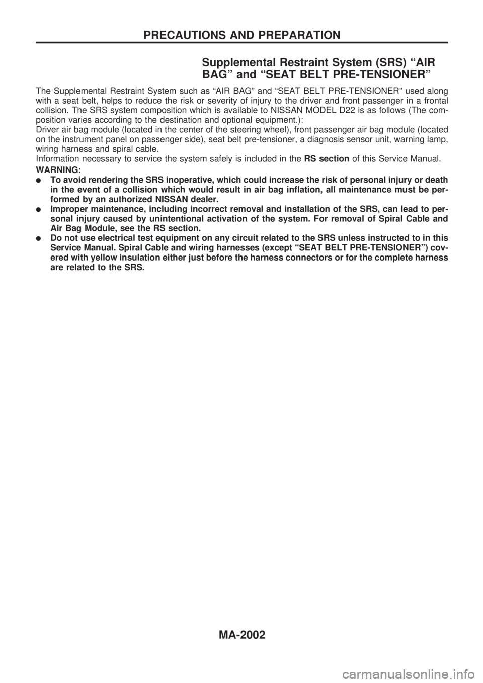
Supplemental Restraint System (SRS) ªAIR
BAGº and ªSEAT BELT PRE-TENSIONERº
The Supplemental Restraint System such as ªAIR BAGº and ªSEAT BELT PRE-TENSIONERº used along
with a seat belt, helps to reduce the risk or severity of injury to the driver and front passenger in a frontal
collision. The SRS system composition which is available to NISSAN MODEL D22 is as follows (The com-
position varies according to the destination and optional equipment.):
Driver air bag module (located in the center of the steering wheel), front passenger air bag module (located
on the instrument panel on passenger side), seat belt pre-tensioner, a diagnosis sensor unit, warning lamp,
wiring harness and spiral cable.
Information necessary to service the system safely is included in theRS sectionof this Service Manual.
WARNING:
lTo avoid rendering the SRS inoperative, which could increase the risk of personal injury or death
in the event of a collision which would result in air bag inflation, all maintenance must be per-
formed by an authorized NISSAN dealer.
lImproper maintenance, including incorrect removal and installation of the SRS, can lead to per-
sonal injury caused by unintentional activation of the system. For removal of Spiral Cable and
Air Bag Module, see the RS section.
lDo not use electrical test equipment on any circuit related to the SRS unless instructed to in this
Service Manual. Spiral Cable and wiring harnesses (except ªSEAT BELT PRE-TENSIONERº) cov-
ered with yellow insulation either just before the harness connectors or for the complete harness
are related to the SRS.
PRECAUTIONS AND PREPARATION
MA-2002
Page 598 of 666
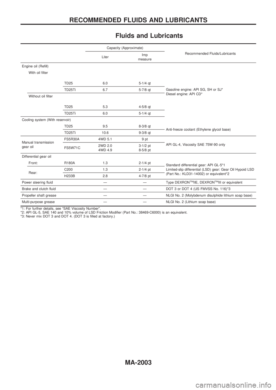
Fluids and Lubricants
Capacity (Approximate)
Recommended Fluids/Lubricants
LiterImp
measure
Engine oil (Refill)
With oil filter
TD25 6.0 5-1/4 qt
Gasoline engine: API SG, SH or SJ*
Diesel engine: API CD* TD25Ti 6.7 5-7/8 qt
Without oil filter
TD25 5.3 4-5/8 qt
TD25Ti 6.0 5-1/4 qt
Cooling system (With reservoir)
TD25 9.5 8-3/8 qt
Anti-freeze coolant (Ethylene glycol base)
TD25Ti 10.6 9-3/8 qt
Manual transmission
gear oilFS5R30A 4WD 5.1 9 pt
API GL-4, Viscosity SAE 75W-90 only
FS5W71C2WD 2.0
4WD 4.93-1/2 pt
8-5/8 pt
Differential gear oil
Front: R180A 1.3 2-1/4 pt
Standard differential gear: API GL-5*1
Limited-slip differential (LSD) gear: Gear Oil Hypoid LSD
(Part No.: KLD31-14002) or equivalent*2 Rear:C200 1.3 2-1/4 pt
H233B 2.8 4-7/8 pt
Power steering fluid Ð Ð Type DEXRON
TMIIE, DEXRONTMIII or equivalent
Brake and clutch fluid Ð Ð DOT 3 or DOT 4 (US FMVSS No. 116)*3
Propeller shaft grease Ð Ð NLGI No. 2 (Molybdenum disulphide lithium soap base)
Multi-purpose grease Ð Ð NLGI No. 2 (Lithium soap base)
*1: For further details, see ªSAE Viscosity Numberº.
*2: API GL-5, SAE 140 and 10% volume of LSD Friction Modifier (Part No.: 38469-C6000) is an equivalent.
*3: Never mix DOT 3 and DOT 4. (DOT 3 is filled at factory.)
RECOMMENDED FLUIDS AND LUBRICANTS
MA-2003
Page 599 of 666
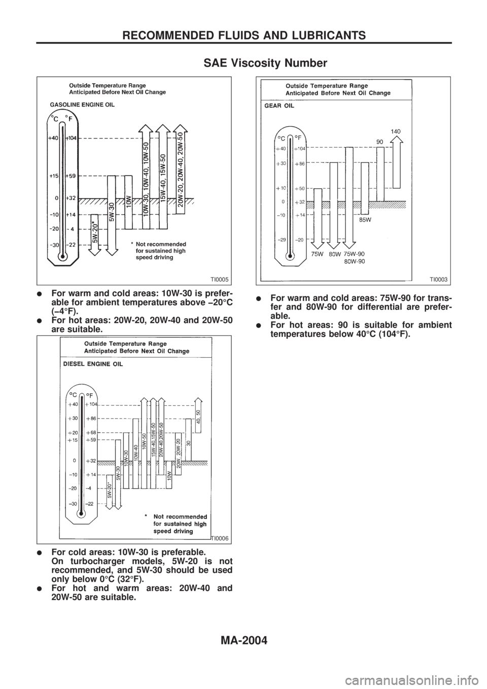
SAE Viscosity Number
lFor warm and cold areas: 10W-30 is prefer-
able for ambient temperatures above þ20ÉC
(þ4ÉF).
lFor hot areas: 20W-20, 20W-40 and 20W-50
are suitable.
lFor cold areas: 10W-30 is preferable.
On turbocharger models, 5W-20 is not
recommended, and 5W-30 should be used
only below 0ÉC (32ÉF).
lFor hot and warm areas: 20W-40 and
20W-50 are suitable.
lFor warm and cold areas: 75W-90 for trans-
fer and 80W-90 for differential are prefer-
able.
lFor hot areas: 90 is suitable for ambient
temperatures below 40ÉC (104ÉF).
TI0005
TI0006
TI0003
RECOMMENDED FLUIDS AND LUBRICANTS
MA-2004
Page 600 of 666
MANUALTRANSAXLE
SECTION
MT
CONTENTS
FS5W71C
MAJOR OVERHAUL ........................................... 2002
Case Components ........................................... 2002
Gear Components - 2WD Model ..................... 2003
Gear Components - 4WD Model ..................... 2004
FS5R30A
MAJOR OVERHAUL ........................................... 2005 Case Components ........................................... 2005
Shift Control Components................................ 2006
FS5W71C & FS5R30A
SERVICE DATA AND SPECIFICATIONS
(SDS).................................................................... 2007
General Specifications ..................................... 2007
MT