NISSAN PICK-UP 2001 Repair Manual
Manufacturer: NISSAN, Model Year: 2001, Model line: PICK-UP, Model: NISSAN PICK-UP 2001Pages: 1306, PDF Size: 31.7 MB
Page 1041 of 1306
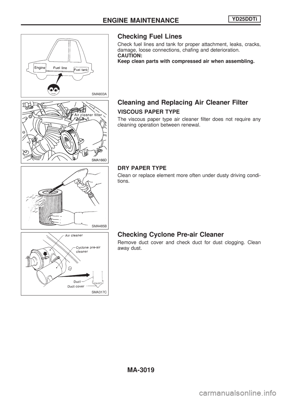
Checking Fuel Lines
Check fuel lines and tank for proper attachment, leaks, cracks,
damage, loose connections, chafing and deterioration.
CAUTION:
Keep clean parts with compressed air when assembling.
Cleaning and Replacing Air Cleaner Filter
VISCOUS PAPER TYPE
The viscous paper type air cleaner filter does not require any
cleaning operation between renewal.
DRY PAPER TYPE
Clean or replace element more often under dusty driving condi-
tions.
Checking Cyclone Pre-air Cleaner
Remove duct cover and check duct for dust clogging. Clean
away dust.
SMA803A
SMA166D
SMA485B
SMA317C
ENGINE MAINTENANCEYD25DDTi
MA-3019
Page 1042 of 1306
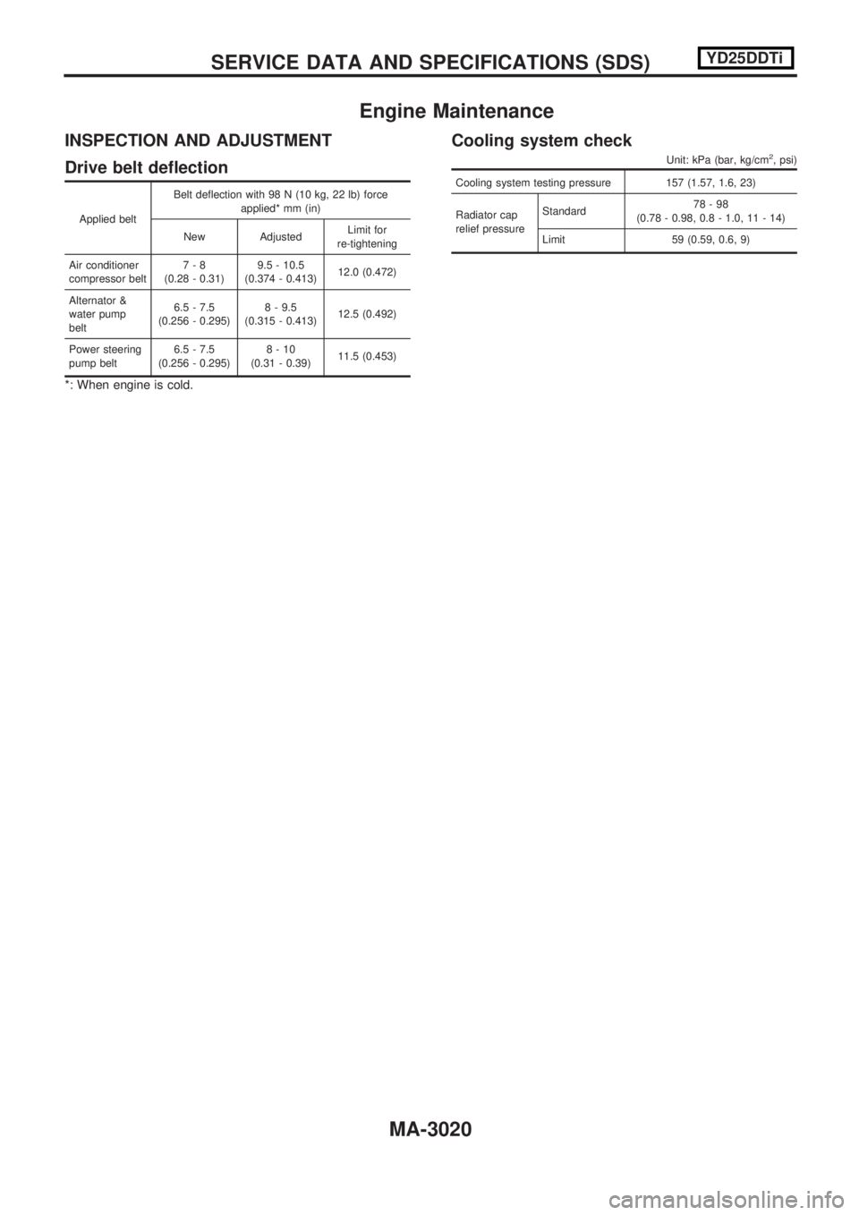
Engine Maintenance
INSPECTION AND ADJUSTMENT
Drive belt deflection
Applied beltBelt deflection with 98 N (10 kg, 22 lb) force
applied* mm (in)
New Adjusted Limit for
re-tightening
Air conditioner
compressor belt 7-8
(0.28 - 0.31) 9.5 - 10.5
(0.374 - 0.413) 12.0 (0.472)
Alternator &
water pump
belt 6.5 - 7.5
(0.256 - 0.295) 8 - 9.5
(0.315 - 0.413) 12.5 (0.492)
Power steering
pump belt 6.5 - 7.5
(0.256 - 0.295) 8-10
(0.31 - 0.39) 11.5 (0.453)
*: When engine is cold.
Cooling system check
Unit: kPa (bar, kg/cm2, psi)
Cooling system testing pressure 157 (1.57, 1.6, 23)
Radiator cap
relief pressureStandard
78-98
(0.78 - 0.98, 0.8 - 1.0, 11 - 14)
Limit 59 (0.59, 0.6, 9)
SERVICEDATAANDSPECIFICATIONS(SDS) YD25DDTi
MA-3020
Page 1043 of 1306
ENGINE LUBRICATION &
COOLING SYSTEMS
SECTION
LC
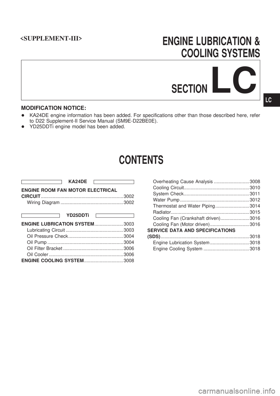
MODIFICATION NOTICE:
+KA24DE engine information has been added. For specifications other than those described here, refer
to D22 Supplement-II Service Manual (SM9E-D22BE0E).
+YD25DDTi engine model has been added.
CONTENTS
KA24DE
ENGINE ROOM FAN MOTOR ELECTRICAL
CIRCUIT............................................................... 3002
Wiring Diagram ................................................ 3002
YD25DDTi
ENGINE LUBRICATION SYSTEM...................... 3003
Lubricating Circuit ............................................ 3003
Oil Pressure Check .......................................... 3004
Oil Pump .......................................................... 3004
Oil Filter Bracket .............................................. 3006
Oil Cooler ......................................................... 3006
ENGINE COOLING SYSTEM.............................. 3008Overheating Cause Analysis ........................... 3008
Cooling Circuit.................................................. 3010
System Check .................................................. 3011
Water Pump ..................................................... 3012
Thermostat and Water Piping .......................... 3014
Radiator............................................................ 3015
Cooling Fan (Crankshaft driven)...................... 3016
Cooling Fan (Motor driven) .............................. 3016
SERVICE DATA AND SPECIFICATIONS
(SDS).................................................................... 3018
Engine Lubrication System .............................. 3018
Engine Cooling System ................................... 3018
LC
Page 1044 of 1306
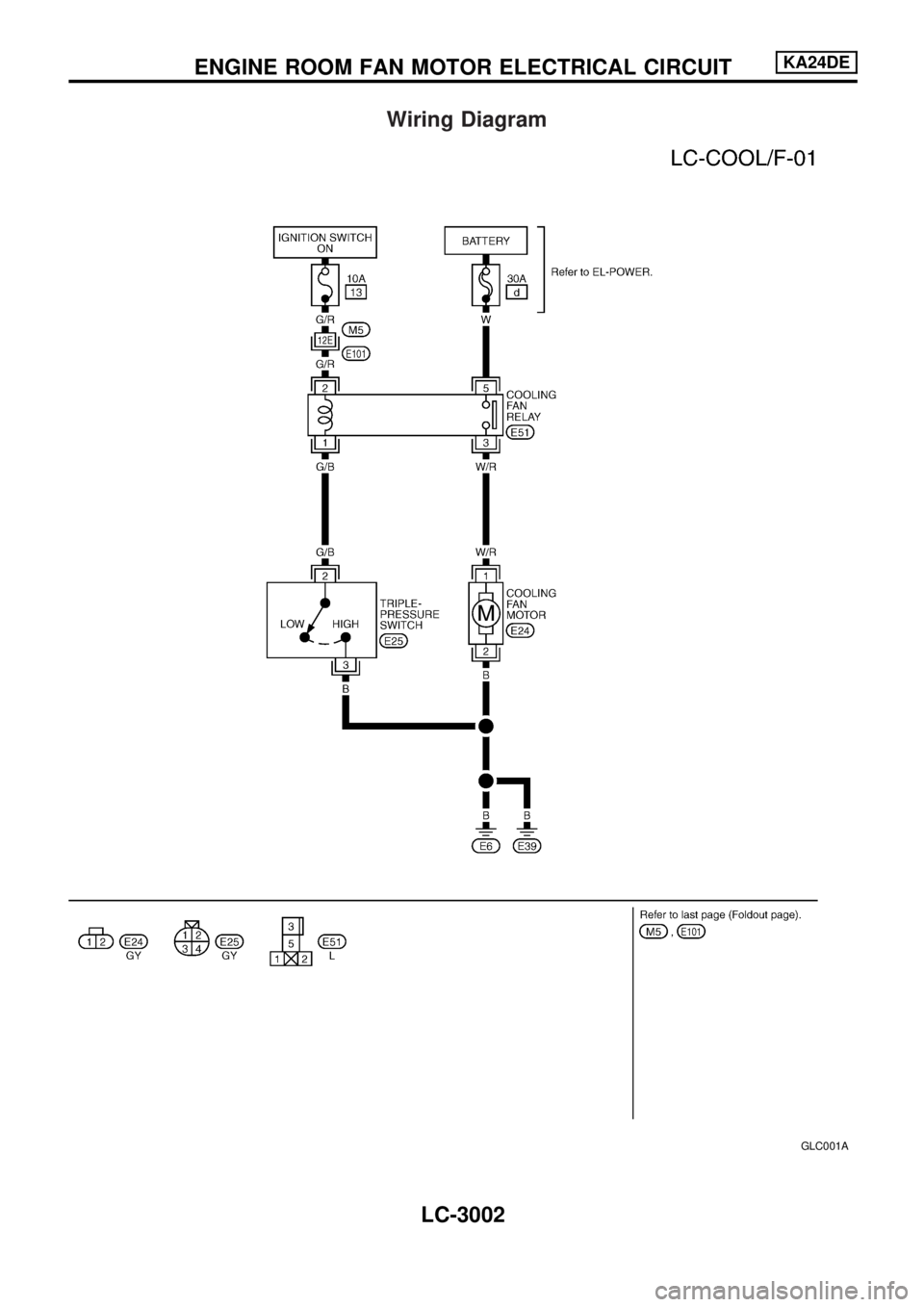
Wiring Diagram
GLC001A
ENGINE ROOM FAN MOTOR ELECTRICAL CIRCUITKA24DE
LC-3002
Page 1045 of 1306
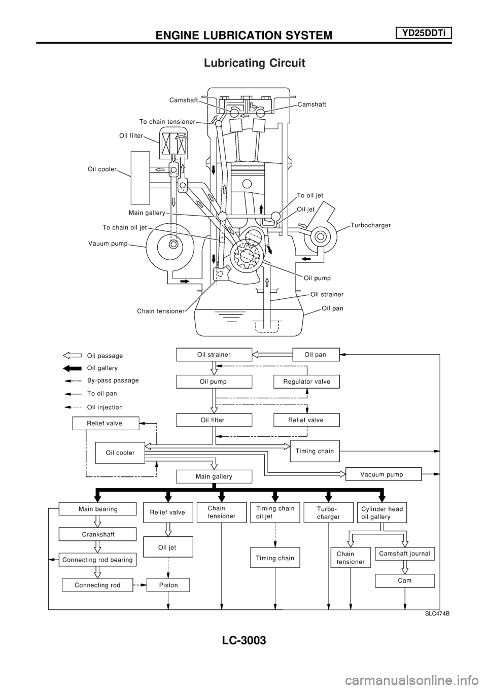
Lubricating Circuit
SLC474B
ENGINE LUBRICATION SYSTEMYD25DDTi
LC-3003
Page 1046 of 1306
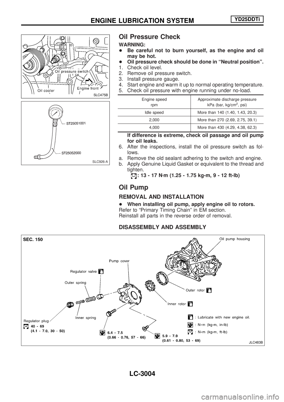
Oil Pressure Check
WARNING:
+Be careful not to burn yourself, as the engine and oil
may be hot.
+Oil pressure check should be done in ªNeutral positionº.
1. Check oil level.
2. Remove oil pressure switch.
3. Install pressure gauge.
4. Start engine and warm it up to normal operating temperature.
5. Check oil pressure with engine running under no-load.
Engine speed
rpmApproximate discharge pressure
kPa (bar, kg/cm2, psi)
Idle speed More than 140 (1.40, 1.43, 20.3)
2,000 More than 270 (2.69, 2.75, 39.1)
4,000 More than 430 (4.29, 4.38, 62.3)
If difference is extreme, check oil passage and oil pump
for oil leaks.
6. After the inspections, install the oil pressure switch as fol-
lows.
a. Remove the old sealant adhering to the switch and engine.
b. Apply Genuine Liquid Gasket or equivalent to the thread and
tighten.
:13-17Nzm (1.25 - 1.75 kg-m,9-12ft-lb)
Oil Pump
REMOVAL AND INSTALLATION
+When installing oil pump, apply engine oil to rotors.
Refer to ªPrimary Timing Chainº in EM section.
Reinstall all parts in the reverse order of removal.
DISASSEMBLY AND ASSEMBLY
SLC475B
SLC926-A
JLC483B
ENGINE LUBRICATION SYSTEMYD25DDTi
LC-3004
Page 1047 of 1306
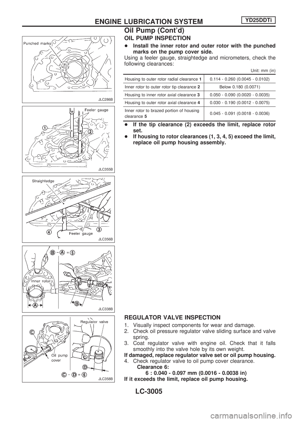
OIL PUMP INSPECTION
+Install the inner rotor and outer rotor with the punched
marks on the pump cover side.
Using a feeler gauge, straightedge and micrometers, check the
following clearances:
Unit: mm (in)
Housing to outer rotor radial clearance10.114 - 0.260 (0.0045 - 0.0102)
Inner rotor to outer rotor tip clearance2Below 0.180 (0.0071)
Housing to inner rotor axial clearance30.050 - 0.090 (0.0020 - 0.0035)
Housing to outer rotor axial clearance40.030 - 0.190 (0.0012 - 0.0075)
Inner rotor to brazed portion of housing
clearance50.045 - 0.091 (0.0018 - 0.0036)
+If the tip clearance (2) exceeds the limit, replace rotor
set.
+If housing to rotor clearances (1, 3, 4, 5) exceed the limit,
replace oil pump housing assembly.
REGULATOR VALVE INSPECTION
1. Visually inspect components for wear and damage.
2. Check oil pressure regulator valve sliding surface and valve
spring.
3. Coat regulator valve with engine oil. Check that it falls
smoothly into the valve hole by its own weight.
If damaged, replace regulator valve set or oil pump housing.
4. Check regulator valve to oil pump cover clearance.
Clearance 6:
6 : 0.040 - 0.097 mm (0.0016 - 0.0038 in)
If it exceeds the limit, replace oil pump housing.
JLC286B
JLC355B
JLC356B
JLC338B
JLC358B
ENGINE LUBRICATION SYSTEMYD25DDTi
Oil Pump (Cont'd)
LC-3005
Page 1048 of 1306
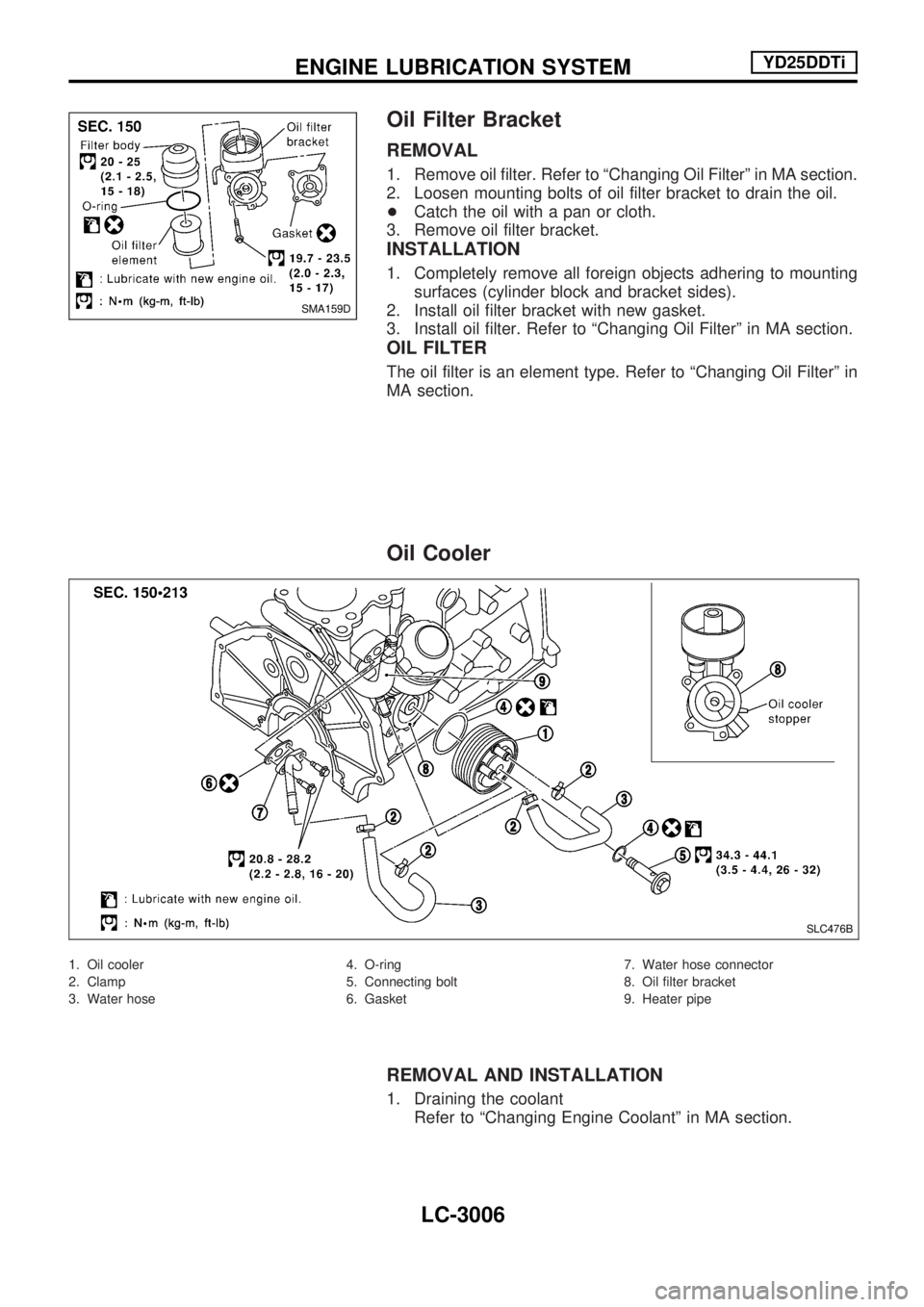
Oil Filter Bracket
REMOVAL
1. Remove oil filter. Refer to ªChanging Oil Filterº in MA section.
2. Loosen mounting bolts of oil filter bracket to drain the oil.
+Catch the oil with a pan or cloth.
3. Remove oil filter bracket.
INSTALLATION
1. Completely remove all foreign objects adhering to mounting
surfaces (cylinder block and bracket sides).
2. Install oil filter bracket with new gasket.
3. Install oil filter. Refer to ªChanging Oil Filterº in MA section.
OIL FILTER
The oil filter is an element type. Refer to ªChanging Oil Filterº in
MA section.
Oil Cooler
1. Oil cooler
2. Clamp
3. Water hose4. O-ring
5. Connecting bolt
6. Gasket7. Water hose connector
8. Oil filter bracket
9. Heater pipe
REMOVAL AND INSTALLATION
1. Draining the coolant
Refer to ªChanging Engine Coolantº in MA section.
SMA159D
SLC476B
ENGINE LUBRICATION SYSTEMYD25DDTi
LC-3006
Page 1049 of 1306
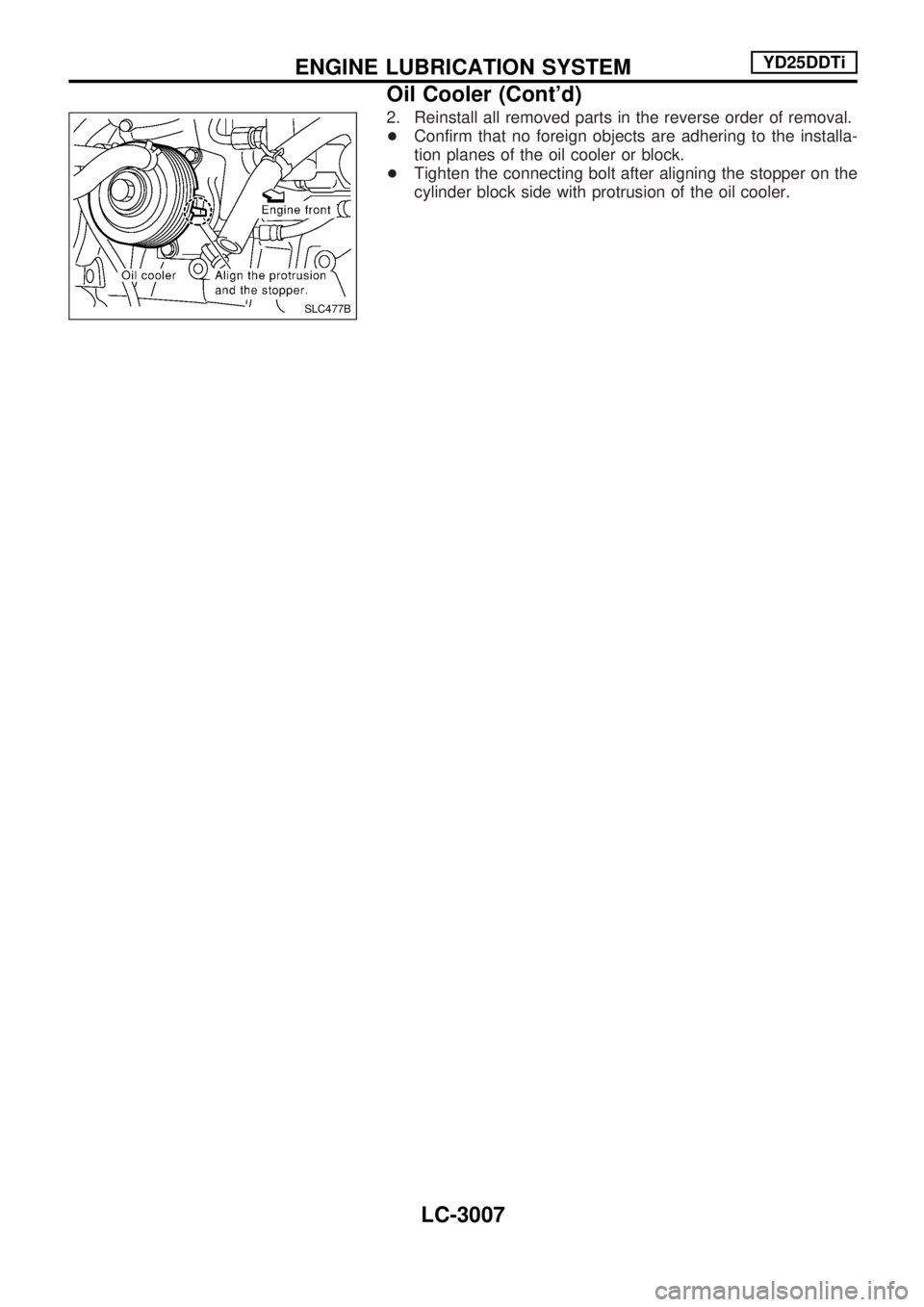
2. Reinstall all removed parts in the reverse order of removal.
+Confirm that no foreign objects are adhering to the installa-
tion planes of the oil cooler or block.
+Tighten the connecting bolt after aligning the stopper on the
cylinder block side with protrusion of the oil cooler.
SLC477B
ENGINE LUBRICATION SYSTEMYD25DDTi
Oil Cooler (Cont'd)
LC-3007
Page 1050 of 1306
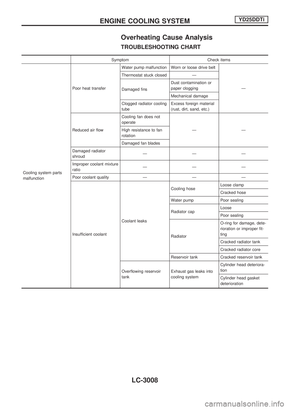
Overheating Cause Analysis
TROUBLESHOOTING CHART
Symptom Check items
Cooling system parts
malfunctionPoor heat transferWater pump malfunction Worn or loose drive belt
Ð Thermostat stuck closed Ð
Damaged finsDust contamination or
paper clogging
Mechanical damage
Clogged radiator cooling
tubeExcess foreign material
(rust, dirt, sand, etc.)
Reduced air flowCooling fan does not
operate
ÐÐ High resistance to fan
rotation
Damaged fan blades
Damaged radiator
shroudÐÐÐ
Improper coolant mixture
ratioÐÐÐ
Poor coolant quality Ð Ð Ð
Insufficient coolantCoolant leaksCooling hoseLoose clamp
Cracked hose
Water pump Poor sealing
Radiator capLoose
Poor sealing
RadiatorO-ring for damage, dete-
rioration or improper fit-
ting
Cracked radiator tank
Cracked radiator core
Reservoir tank Cracked reservoir tank
Overflowing reservoir
tankExhaust gas leaks into
cooling systemCylinder head deteriora-
tion
Cylinder head gasket
deterioration
ENGINE COOLING SYSTEMYD25DDTi
LC-3008