NISSAN PICK-UP 2001 Repair Manual
Manufacturer: NISSAN, Model Year: 2001, Model line: PICK-UP, Model: NISSAN PICK-UP 2001Pages: 1306, PDF Size: 31.7 MB
Page 1181 of 1306
Meter/Gauge Operation and Odo/Trip Meter
Segment Check in Diagnosis Mode
DIAGNOSIS FUNCTION
+Odo/trip meter segment can be checked in diagnosis mode.
+Meters/gauges can be checked in diagnosis mode.
HOW TO ALTERNATE DIAGNOSIS MODE
1. Turn ignition switch to ON and change odo/trip meter to
ªTRIP Aº or ªTRIP Bº.
2. Turn ignition switch to OFF.
3. Turn ignition switch to ON when pushing odo/trip meter
switch.
4. Confirm that trip meter indicates ª000.0º.
5. Push odo/trip meter switch more than three times within 5
seconds.
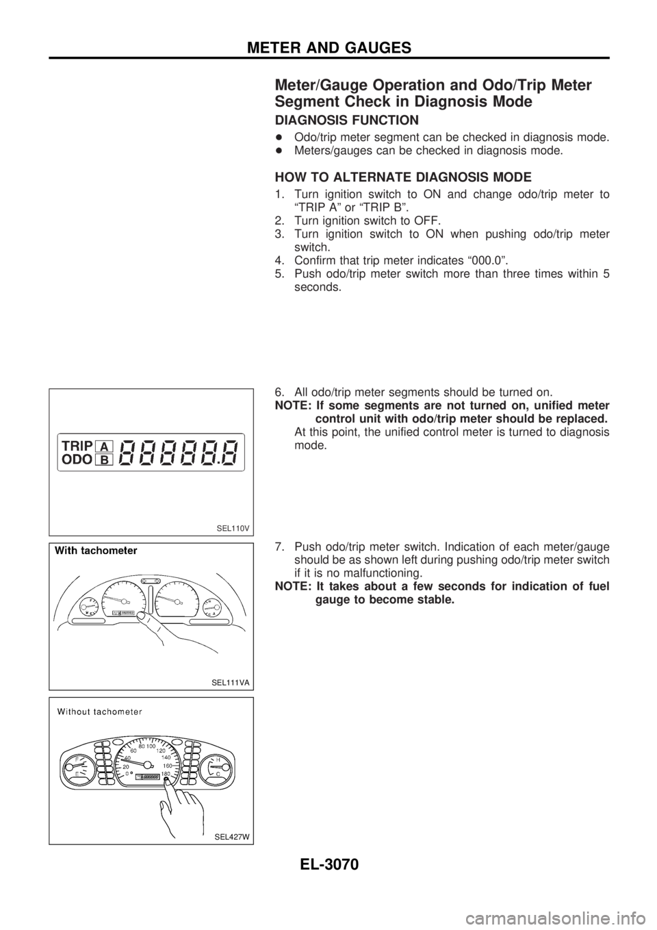
6. All odo/trip meter segments should be turned on.
NOTE: If some segments are not turned on, unified meter
control unit with odo/trip meter should be replaced.
At this point, the unified control meter is turned to diagnosis
mode.
7. Push odo/trip meter switch. Indication of each meter/gauge
should be as shown left during pushing odo/trip meter switch
if it is no malfunctioning.
NOTE: It takes about a few seconds for indication of fuel
gauge to become stable.
SEL110V
SEL111VA
SEL427W
METER AND GAUGES
EL-3070
Page 1182 of 1306
Trouble Diagnoses/With Tachometer
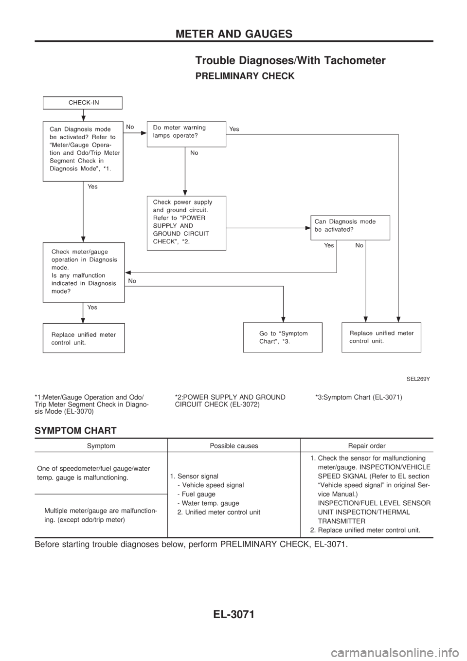
PRELIMINARY CHECK
*1:Meter/Gauge Operation and Odo/
Trip Meter Segment Check in Diagno-
sis Mode (EL-3070)*2:POWER SUPPLY AND GROUND
CIRCUIT CHECK (EL-3072)*3:Symptom Chart (EL-3071)
SYMPTOM CHART
Symptom Possible causes Repair order
One of speedometer/fuel gauge/water
temp. gauge is malfunctioning.1. Sensor signal
- Vehicle speed signal
- Fuel gauge
- Water temp. gauge
2. Unified meter control unit1. Check the sensor for malfunctioning
meter/gauge. INSPECTION/VEHICLE
SPEED SIGNAL (Refer to EL section
ªVehicle speed signalº in original Ser-
vice Manual.)
INSPECTION/FUEL LEVEL SENSOR
UNIT INSPECTION/THERMAL
TRANSMITTER
2. Replace unified meter control unit. Multiple meter/gauge are malfunction-
ing. (except odo/trip meter)
Before starting trouble diagnoses below, perform PRELIMINARY CHECK, EL-3071.
SEL269Y
METER AND GAUGES
EL-3071
Page 1183 of 1306
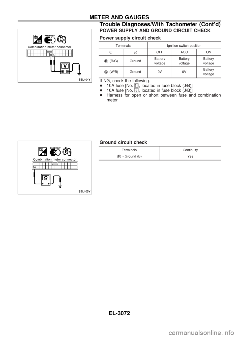
POWER SUPPLY AND GROUND CIRCUIT CHECK
Power supply circuit check
Terminals Ignition switch position
Å@OFF ACC ON
V18(R/G) GroundBattery
voltageBattery
voltageBattery
voltage
V17(W/B) Ground 0V 0VBattery
voltage
If NG, check the following.
+10A fuse [No.
11, located in fuse block (J/B)]
+10A fuse [No.
6, located in fuse block (J/B)]
+Harness for open or short between fuse and combination
meter
Ground circuit check
Terminals Continuity
V24- Ground (B) Yes
SEL404Y
SEL405Y
METER AND GAUGES
Trouble Diagnoses/With Tachometer (Cont'd)
EL-3072
Page 1184 of 1306
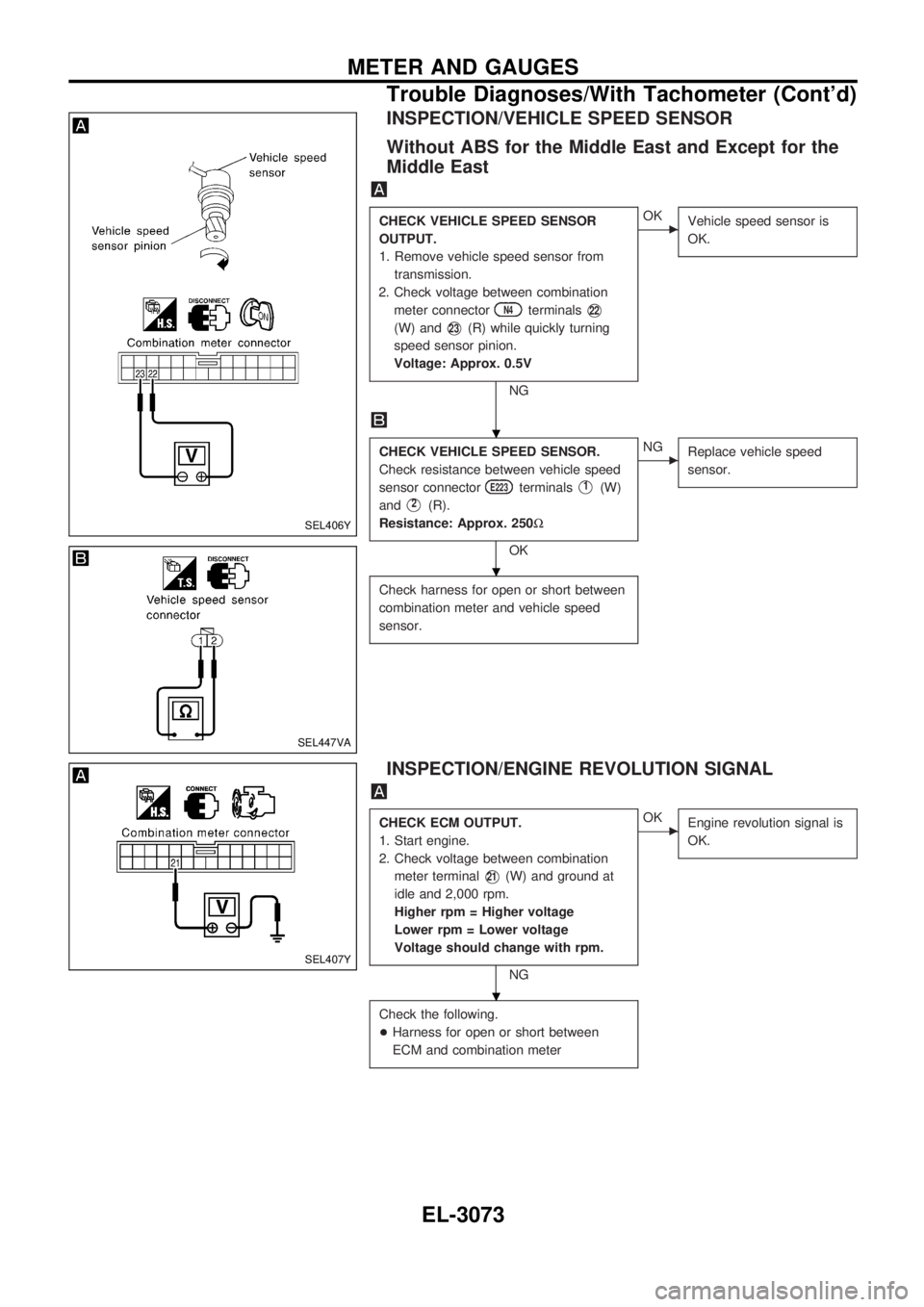
INSPECTION/VEHICLE SPEED SENSOR
Without ABS for the Middle East and Except for the
Middle East
CHECK VEHICLE SPEED SENSOR
OUTPUT.
1. Remove vehicle speed sensor from
transmission.
2. Check voltage between combination
meter connector
N4terminalsV22
(W) andV23(R) while quickly turning
speed sensor pinion.
Voltage: Approx. 0.5V
NG
cOK
Vehicle speed sensor is
OK.
CHECK VEHICLE SPEED SENSOR.
Check resistance between vehicle speed
sensor connector
E223terminalsV1(W)
and
V2(R).
Resistance: Approx. 250W
OK
cNG
Replace vehicle speed
sensor.
Check harness for open or short between
combination meter and vehicle speed
sensor.
INSPECTION/ENGINE REVOLUTION SIGNAL
CHECK ECM OUTPUT.
1. Start engine.
2. Check voltage between combination
meter terminal
V21(W) and ground at
idle and 2,000 rpm.
Higher rpm = Higher voltage
Lower rpm = Lower voltage
Voltage should change with rpm.
NG
cOK
Engine revolution signal is
OK.
Check the following.
+Harness for open or short between
ECM and combination meter
SEL406Y
SEL447VA
SEL407Y
.
.
.
METER AND GAUGES
Trouble Diagnoses/With Tachometer (Cont'd)
EL-3073
Page 1185 of 1306
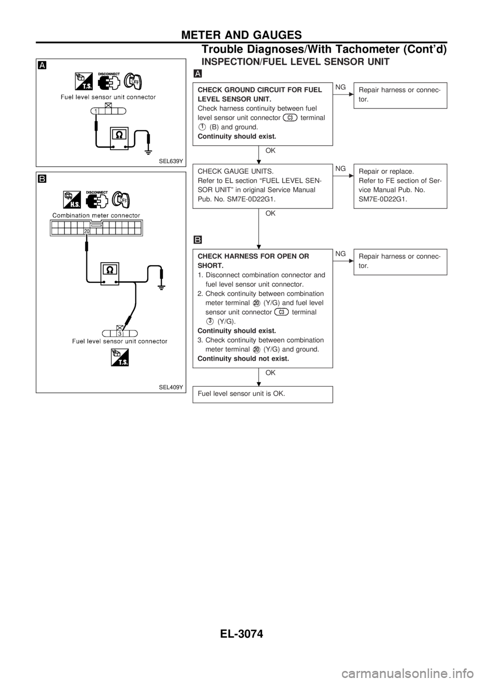
INSPECTION/FUEL LEVEL SENSOR UNIT
CHECK GROUND CIRCUIT FOR FUEL
LEVEL SENSOR UNIT.
Check harness continuity between fuel
level sensor unit connector
C3terminal
V1(B) and ground.
Continuity should exist.
OK
cNG
Repair harness or connec-
tor.
CHECK GAUGE UNITS.
Refer to EL section ªFUEL LEVEL SEN-
SOR UNITº in original Service Manual
Pub. No. SM7E-0D22G1.
OK
cNG
Repair or replace.
Refer to FE section of Ser-
vice Manual Pub. No.
SM7E-0D22G1.
CHECK HARNESS FOR OPEN OR
SHORT.
1. Disconnect combination connector and
fuel level sensor unit connector.
2. Check continuity between combination
meter terminal
V20(Y/G) and fuel level
sensor unit connector
C3terminal
V3(Y/G).
Continuity should exist.
3. Check continuity between combination
meter terminal
V20(Y/G) and ground.
Continuity should not exist.
OK
cNG
Repair harness or connec-
tor.
Fuel level sensor unit is OK.
SEL639Y
SEL409Y
.
.
.
METER AND GAUGES
Trouble Diagnoses/With Tachometer (Cont'd)
EL-3074
Page 1186 of 1306
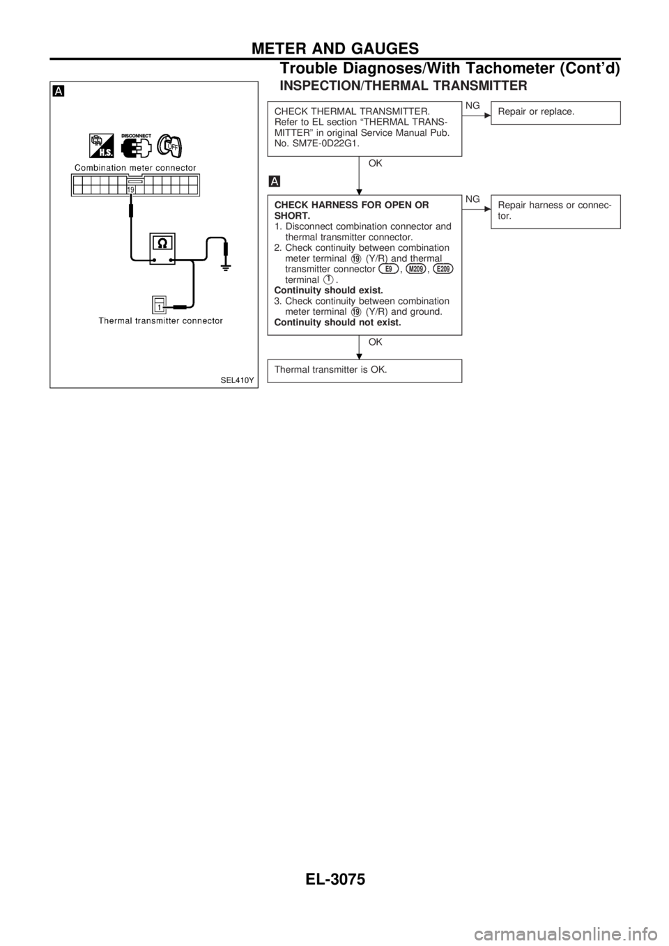
INSPECTION/THERMAL TRANSMITTER
CHECK THERMAL TRANSMITTER.
Refer to EL section ªTHERMAL TRANS-
MITTERº in original Service Manual Pub.
No. SM7E-0D22G1.
OK
cNG
Repair or replace.
CHECK HARNESS FOR OPEN OR
SHORT.
1. Disconnect combination connector and
thermal transmitter connector.
2. Check continuity between combination
meter terminal
V19(Y/R) and thermal
transmitter connectorE9,M209,E209terminalV1.
Continuity should exist.
3. Check continuity between combination
meter terminal
V19(Y/R) and ground.
Continuity should not exist.
OK
cNG
Repair harness or connec-
tor.
Thermal transmitter is OK.SEL410Y
.
.
METER AND GAUGES
Trouble Diagnoses/With Tachometer (Cont'd)
EL-3075
Page 1187 of 1306
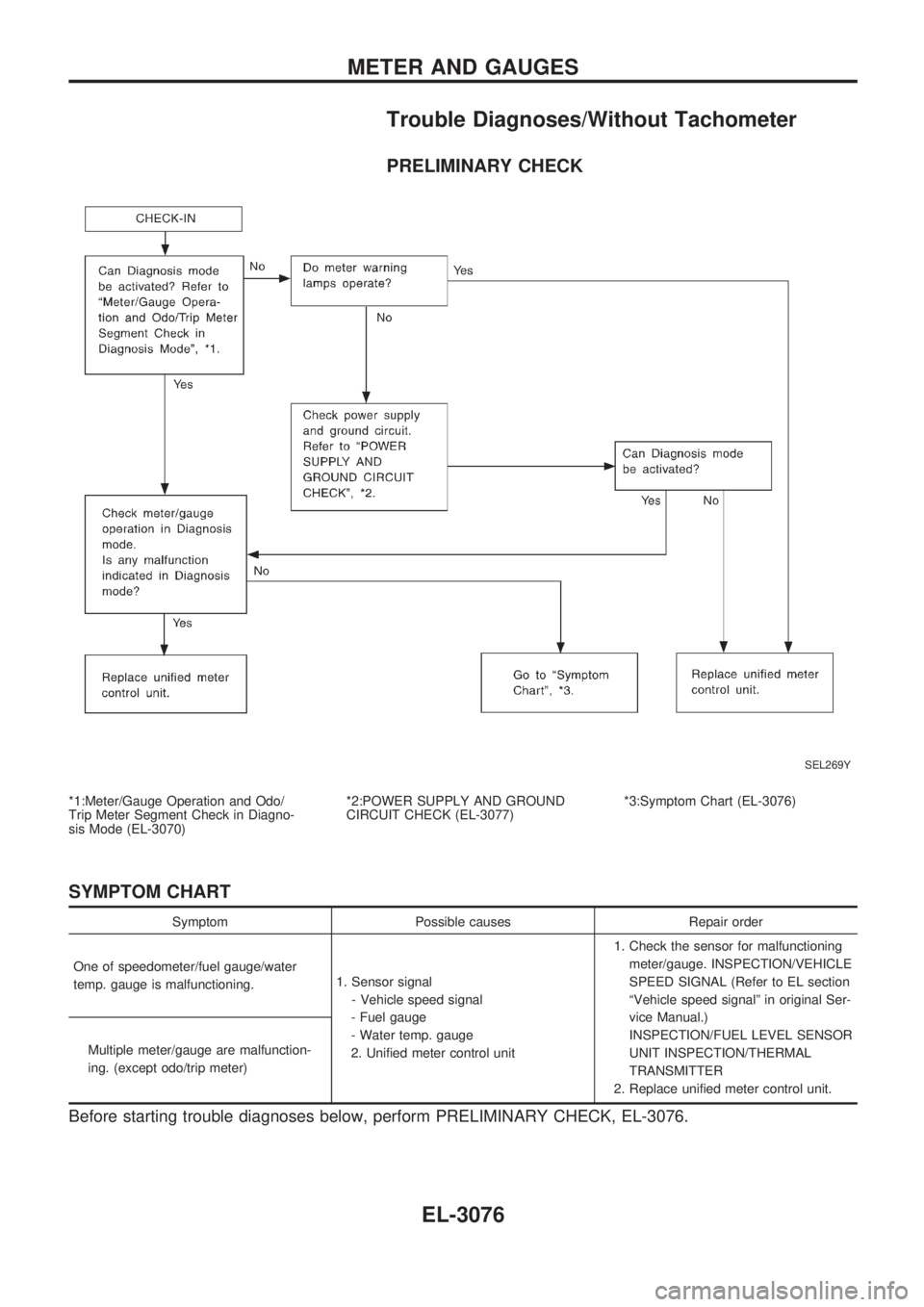
Trouble Diagnoses/Without Tachometer
PRELIMINARY CHECK
*1:Meter/Gauge Operation and Odo/
Trip Meter Segment Check in Diagno-
sis Mode (EL-3070)*2:POWER SUPPLY AND GROUND
CIRCUIT CHECK (EL-3077)*3:Symptom Chart (EL-3076)
SYMPTOM CHART
Symptom Possible causes Repair order
One of speedometer/fuel gauge/water
temp. gauge is malfunctioning.1. Sensor signal
- Vehicle speed signal
- Fuel gauge
- Water temp. gauge
2. Unified meter control unit1. Check the sensor for malfunctioning
meter/gauge. INSPECTION/VEHICLE
SPEED SIGNAL (Refer to EL section
ªVehicle speed signalº in original Ser-
vice Manual.)
INSPECTION/FUEL LEVEL SENSOR
UNIT INSPECTION/THERMAL
TRANSMITTER
2. Replace unified meter control unit. Multiple meter/gauge are malfunction-
ing. (except odo/trip meter)
Before starting trouble diagnoses below, perform PRELIMINARY CHECK, EL-3076.
SEL269Y
METER AND GAUGES
EL-3076
Page 1188 of 1306
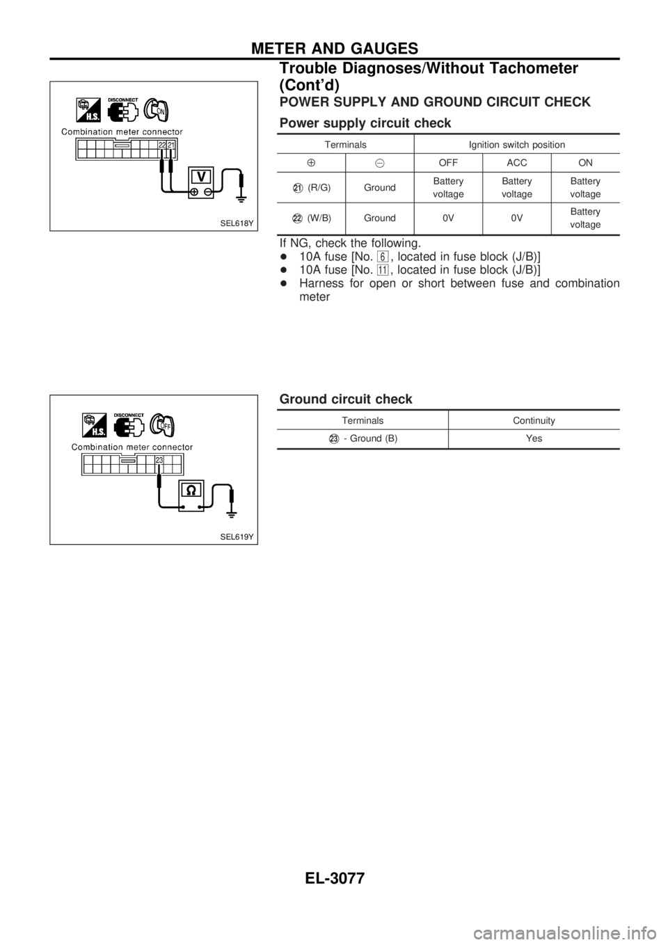
POWER SUPPLY AND GROUND CIRCUIT CHECK
Power supply circuit check
Terminals Ignition switch position
Å@OFF ACC ON
V21(R/G) GroundBattery
voltageBattery
voltageBattery
voltage
V22(W/B) Ground 0V 0VBattery
voltage
If NG, check the following.
+10A fuse [No.
6, located in fuse block (J/B)]
+10A fuse [No.
11, located in fuse block (J/B)]
+Harness for open or short between fuse and combination
meter
Ground circuit check
Terminals Continuity
V23- Ground (B) Yes
SEL618Y
SEL619Y
METER AND GAUGES
Trouble Diagnoses/Without Tachometer
(Cont'd)
EL-3077
Page 1189 of 1306
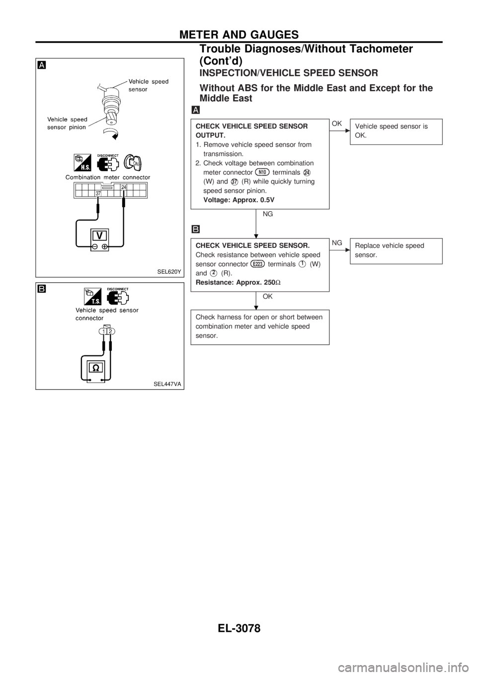
INSPECTION/VEHICLE SPEED SENSOR
Without ABS for the Middle East and Except for the
Middle East
CHECK VEHICLE SPEED SENSOR
OUTPUT.
1. Remove vehicle speed sensor from
transmission.
2. Check voltage between combination
meter connector
N10terminalsV24
(W) andV37(R) while quickly turning
speed sensor pinion.
Voltage: Approx. 0.5V
NG
cOK
Vehicle speed sensor is
OK.
CHECK VEHICLE SPEED SENSOR.
Check resistance between vehicle speed
sensor connector
E223terminalsV1(W)
and
V2(R).
Resistance: Approx. 250W
OK
cNG
Replace vehicle speed
sensor.
Check harness for open or short between
combination meter and vehicle speed
sensor.
SEL620Y
SEL447VA
.
.
METER AND GAUGES
Trouble Diagnoses/Without Tachometer
(Cont'd)
EL-3078
Page 1190 of 1306
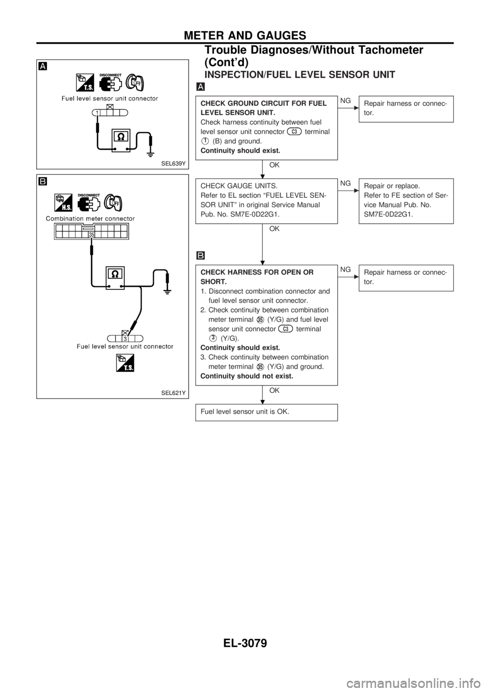
INSPECTION/FUEL LEVEL SENSOR UNIT
CHECK GROUND CIRCUIT FOR FUEL
LEVEL SENSOR UNIT.
Check harness continuity between fuel
level sensor unit connector
C3terminal
V1(B) and ground.
Continuity should exist.
OK
cNG
Repair harness or connec-
tor.
CHECK GAUGE UNITS.
Refer to EL section ªFUEL LEVEL SEN-
SOR UNITº in original Service Manual
Pub. No. SM7E-0D22G1.
OK
cNG
Repair or replace.
Refer to FE section of Ser-
vice Manual Pub. No.
SM7E-0D22G1.
CHECK HARNESS FOR OPEN OR
SHORT.
1. Disconnect combination connector and
fuel level sensor unit connector.
2. Check continuity between combination
meter terminal
V35(Y/G) and fuel level
sensor unit connector
C3terminal
V3(Y/G).
Continuity should exist.
3. Check continuity between combination
meter terminal
V35(Y/G) and ground.
Continuity should not exist.
OK
cNG
Repair harness or connec-
tor.
Fuel level sensor unit is OK.
SEL639Y
SEL621Y
.
.
.
METER AND GAUGES
Trouble Diagnoses/Without Tachometer
(Cont'd)
EL-3079