NISSAN PICK-UP 2001 Repair Manual
PICK-UP 2001
NISSAN
NISSAN
https://www.carmanualsonline.info/img/5/57372/w960_57372-0.png
NISSAN PICK-UP 2001 Repair Manual
Trending: tire pressure, transmission, carburetor, transmission fluid, stop start, check engine, gas type
Page 911 of 1306
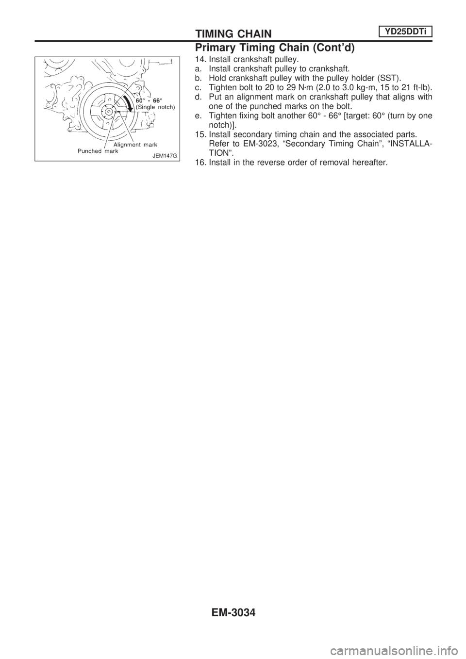
14. Install crankshaft pulley.
a. Install crankshaft pulley to crankshaft.
b. Hold crankshaft pulley with the pulley holder (SST).
c. Tighten bolt to 20 to 29 Nzm (2.0 to 3.0 kg-m, 15 to 21 ft-lb).
d. Put an alignment mark on crankshaft pulley that aligns with
one of the punched marks on the bolt.
e. Tighten fixing bolt another 60É - 66É [target: 60É (turn by one
notch)].
15. Install secondary timing chain and the associated parts.
Refer to EM-3023, ªSecondary Timing Chainº, ªINSTALLA-
TIONº.
16. Install in the reverse order of removal hereafter.
JEM147G
TIMING CHAINYD25DDTi
Primary Timing Chain (Cont'd)
EM-3034
Page 912 of 1306
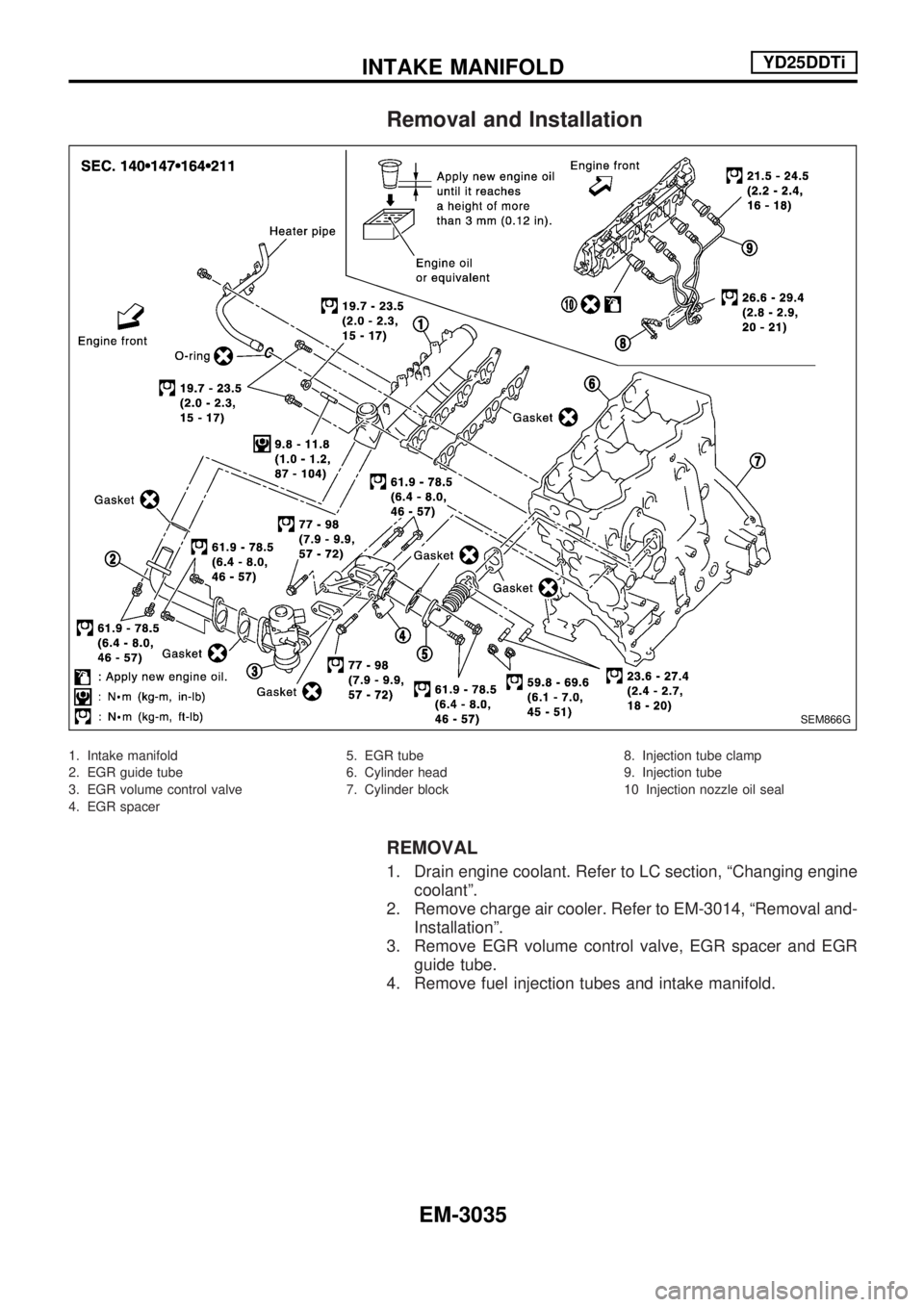
Removal and Installation
1. Intake manifold
2. EGR guide tube
3. EGR volume control valve
4. EGR spacer5. EGR tube
6. Cylinder head
7. Cylinder block8. Injection tube clamp
9. Injection tube
10 Injection nozzle oil seal
REMOVAL
1. Drain engine coolant. Refer to LC section, ªChanging engine
coolantº.
2. Remove charge air cooler. Refer to EM-3014, ªRemoval and-
Installationº.
3. Remove EGR volume control valve, EGR spacer and EGR
guide tube.
4. Remove fuel injection tubes and intake manifold.
SEM866G
INTAKE MANIFOLDYD25DDTi
EM-3035
Page 913 of 1306
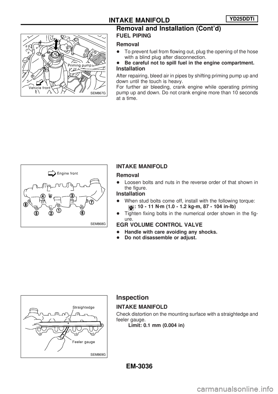
FUEL PIPING
Removal
+To prevent fuel from flowing out, plug the opening of the hose
with a blind plug after disconnection.
+Be careful not to spill fuel in the engine compartment.
Installation
After repairing, bleed air in pipes by shifting priming pump up and
down until the touch is heavy.
For further air bleeding, crank engine while operating priming
pump up and down. Do not crank engine more than 10 seconds
at a time.
INTAKE MANIFOLD
Removal
+Loosen bolts and nuts in the reverse order of that shown in
the figure.
Installation
+When stud bolts come off, install with the following torque:
:10-11Nzm (1.0 - 1.2 kg-m, 87 - 104 in-lb)
+Tighten fixing bolts in the numerical order shown in the fig-
ure.
EGR VOLUME CONTROL VALVE
+Handle with care avoiding any shocks.
+Do not disassemble or adjust.
Inspection
INTAKE MANIFOLD
Check distortion on the mounting surface with a straightedge and
feeler gauge.
Limit: 0.1 mm (0.004 in)
SEM867G
SEM868G
SEM869G
INTAKE MANIFOLDYD25DDTi
Removal and Installation (Cont'd)
EM-3036
Page 914 of 1306
Removal and Installation
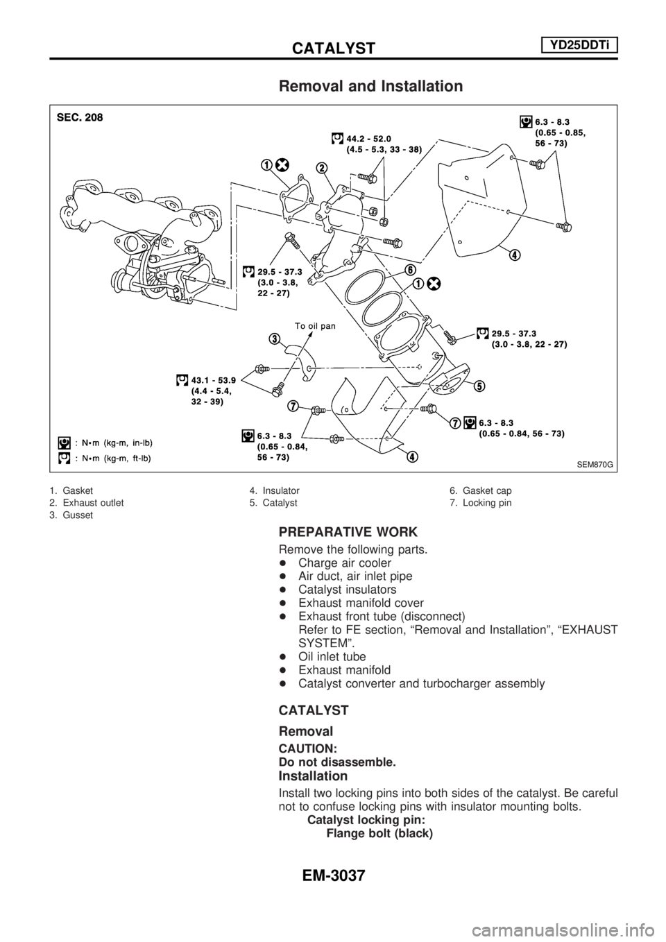
1. Gasket
2. Exhaust outlet
3. Gusset4. Insulator
5. Catalyst6. Gasket cap
7. Locking pin
PREPARATIVE WORK
Remove the following parts.
+Charge air cooler
+Air duct, air inlet pipe
+Catalyst insulators
+Exhaust manifold cover
+Exhaust front tube (disconnect)
Refer to FE section, ªRemoval and Installationº, ªEXHAUST
SYSTEMº.
+Oil inlet tube
+Exhaust manifold
+Catalyst converter and turbocharger assembly
CATALYST
Removal
CAUTION:
Do not disassemble.
Installation
Install two locking pins into both sides of the catalyst. Be careful
not to confuse locking pins with insulator mounting bolts.
Catalyst locking pin:
Flange bolt (black)
SEM870G
CATALYSTYD25DDTi
EM-3037
Page 915 of 1306
Insulator mounting bolt:
Washer bolt (silver or yellow)
GUSSET
Installation
Pushing gussets against the oil pan and the catalyst, temporarily
tighten the mounting bolt. And then tighten it to the specified
torque.
CATALYSTYD25DDTi
Removal and Installation (Cont'd)
EM-3038
Page 916 of 1306
Removal and Installation
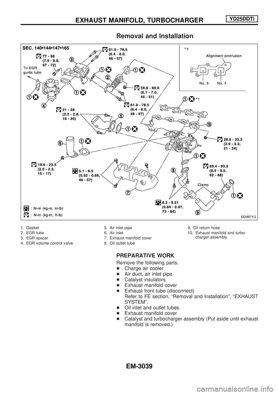
1. Gasket
2. EGR tube
3. EGR spacer
4. EGR volume control valve5. Air inlet pipe
6. Air inlet
7. Exhaust manifold cover
8. Oil outlet tube9. Oil return hose
10. Exhaust manifold and turbo-
charger assembly
PREPARATIVE WORK
Remove the following parts.
+Charge air cooler
+Air duct, air inlet pipe
+Catalyst insulators
+Exhaust manifold cover
+Exhaust front tube (disconnect)
Refer to FE section, ªRemoval and Installationº, ªEXHAUST
SYSTEMº.
+Oil inlet and outlet tubes
+Exhaust manifold cover
+Catalyst and turbocharger assembly (Put aside until exhaust
manifold is removed.)
SEM871G
EXHAUST MANIFOLD, TURBOCHARGERYD25DDTi
EM-3039
Page 917 of 1306
EXHAUST MANIFOLD AND TURBOCHARGER
Removal
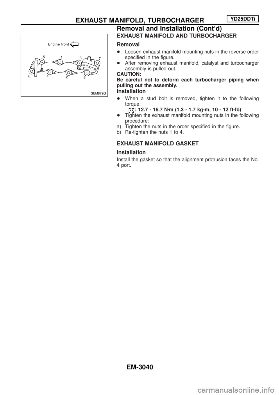
+Loosen exhaust manifold mounting nuts in the reverse order
specified in the figure.
+After removing exhaust manifold, catalyst and turbocharger
assembly is pulled out.
CAUTION:
Be careful not to deform each turbocharger piping when
pulling out the assembly.
Installation
+When a stud bolt is removed, tighten it to the following
torque:
: 12.7 - 16.7 Nzm (1.3 - 1.7 kg-m, 10 - 12 ft-lb)
+Tighten the exhaust manifold mounting nuts in the following
procedure:
a) Tighten the nuts in the order specified in the figure.
b) Re-tighten the nuts 1 to 4.
EXHAUST MANIFOLD GASKET
Installation
Install the gasket so that the alignment protrusion faces the No.
4 port.
SEM872G
EXHAUST MANIFOLD, TURBOCHARGERYD25DDTi
Removal and Installation (Cont'd)
EM-3040
Page 918 of 1306
Disassembly and Assembly
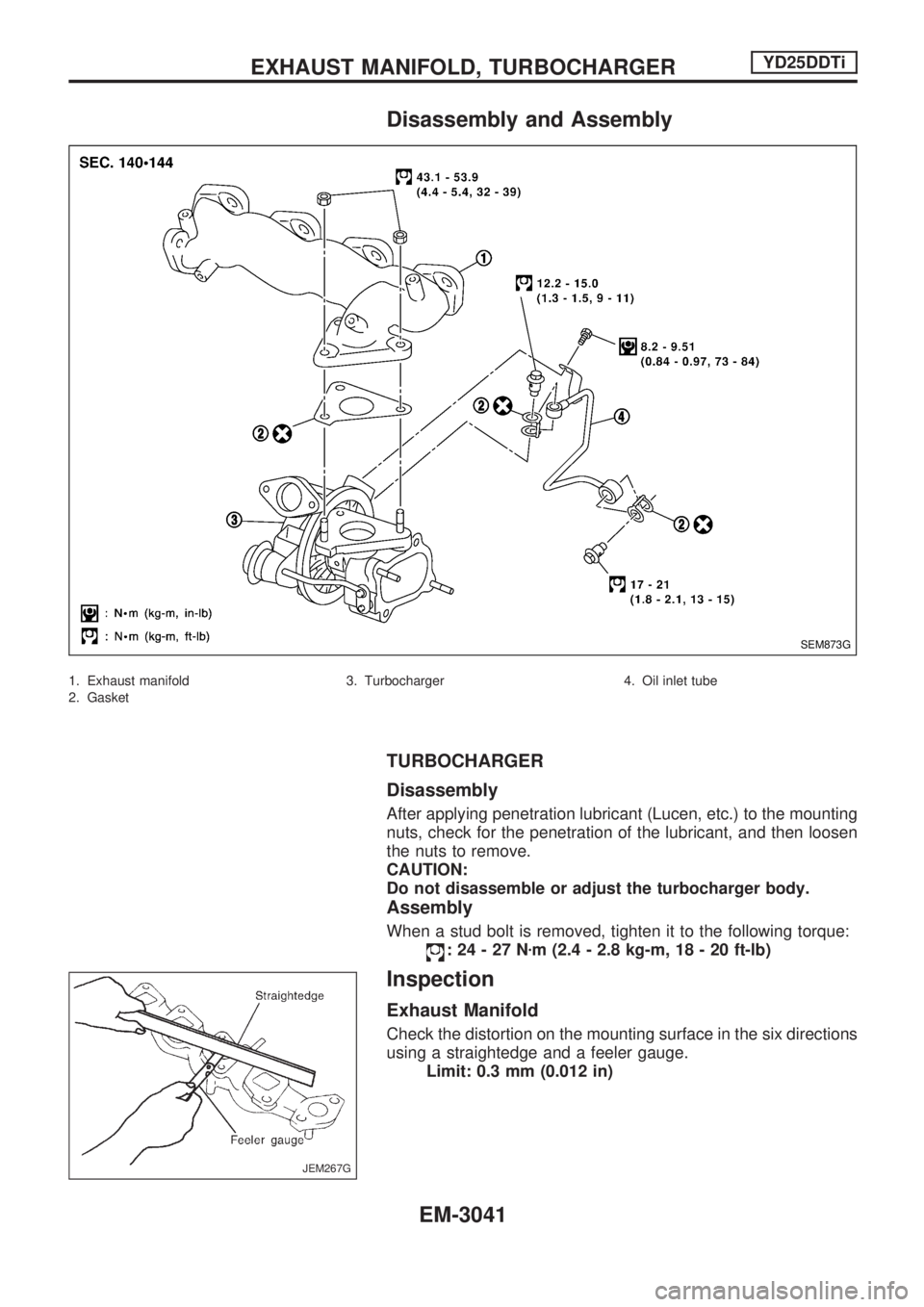
1. Exhaust manifold
2. Gasket3. Turbocharger 4. Oil inlet tube
TURBOCHARGER
Disassembly
After applying penetration lubricant (Lucen, etc.) to the mounting
nuts, check for the penetration of the lubricant, and then loosen
the nuts to remove.
CAUTION:
Do not disassemble or adjust the turbocharger body.
Assembly
When a stud bolt is removed, tighten it to the following torque:
:24-27Nzm (2.4 - 2.8 kg-m, 18 - 20 ft-lb)
Inspection
Exhaust Manifold
Check the distortion on the mounting surface in the six directions
using a straightedge and a feeler gauge.
Limit: 0.3 mm (0.012 in)
SEM873G
JEM267G
EXHAUST MANIFOLD, TURBOCHARGERYD25DDTi
EM-3041
Page 919 of 1306
TURBOCHARGER
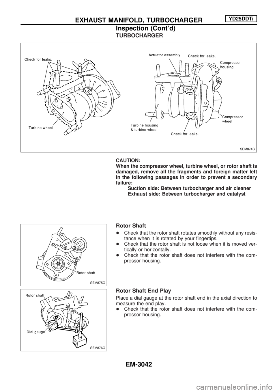
CAUTION:
When the compressor wheel, turbine wheel, or rotor shaft is
damaged, remove all the fragments and foreign matter left
in the following passages in order to prevent a secondary
failure:
Suction side: Between turbocharger and air cleaner
Exhaust side: Between turbocharger and catalyst
Rotor Shaft
+Check that the rotor shaft rotates smoothly without any resis-
tance when it is rotated by your fingertips.
+Check that the rotor shaft is not loose when it is moved ver-
tically or horizontally.
+Check that the rotor shaft does not interfere with the com-
pressor housing.
Rotor Shaft End Play
Place a dial gauge at the rotor shaft end in the axial direction to
measure the end play.
+Check that the rotor shaft does not interfere with the com-
pressor housing.
SEM874G
SEM875G
SEM876G
EXHAUST MANIFOLD, TURBOCHARGERYD25DDTi
Inspection (Cont'd)
EM-3042
Page 920 of 1306
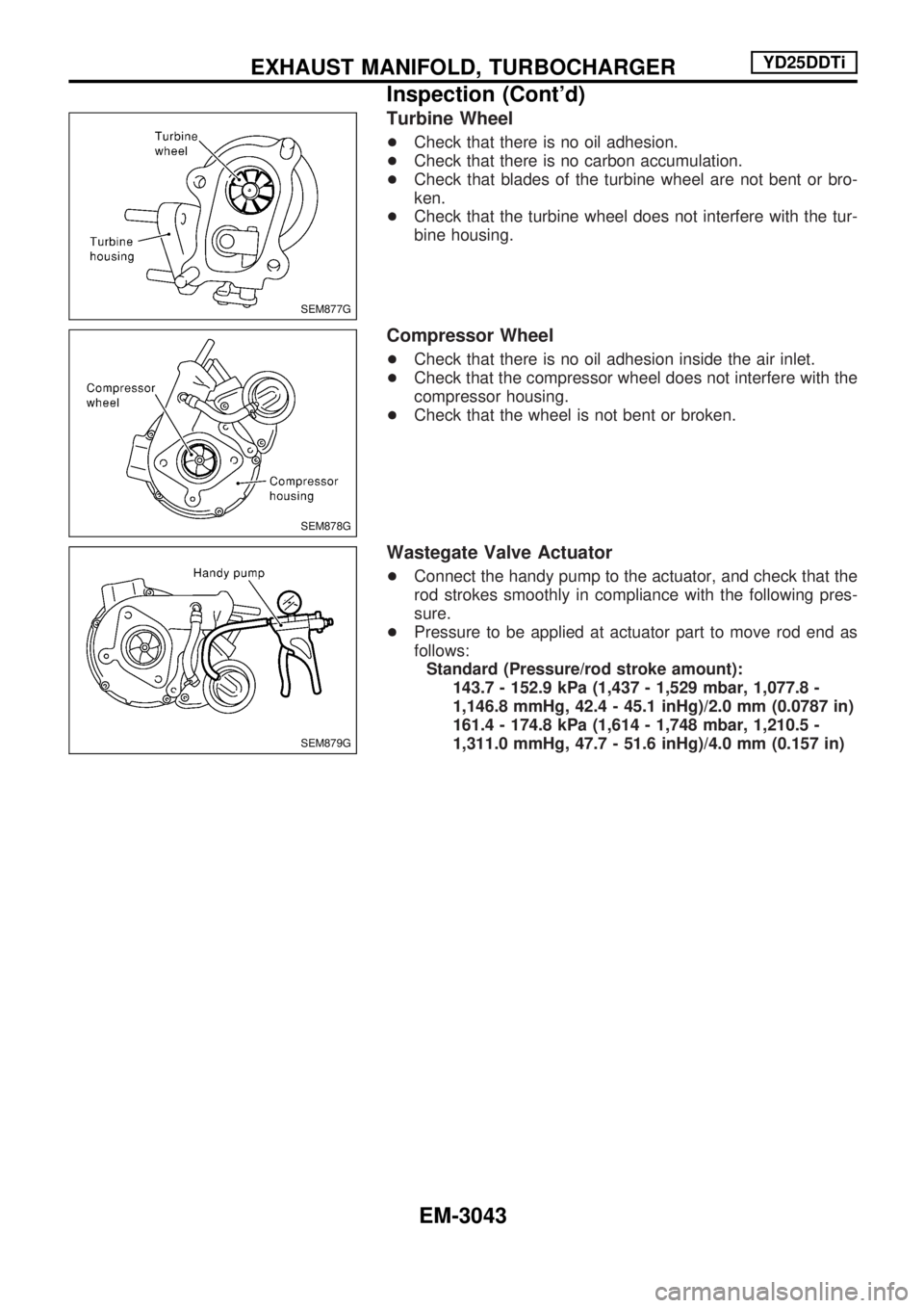
Turbine Wheel
+Check that there is no oil adhesion.
+Check that there is no carbon accumulation.
+Check that blades of the turbine wheel are not bent or bro-
ken.
+Check that the turbine wheel does not interfere with the tur-
bine housing.
Compressor Wheel
+Check that there is no oil adhesion inside the air inlet.
+Check that the compressor wheel does not interfere with the
compressor housing.
+Check that the wheel is not bent or broken.
Wastegate Valve Actuator
+Connect the handy pump to the actuator, and check that the
rod strokes smoothly in compliance with the following pres-
sure.
+Pressure to be applied at actuator part to move rod end as
follows:
Standard (Pressure/rod stroke amount):
143.7 - 152.9 kPa (1,437 - 1,529 mbar, 1,077.8 -
1,146.8 mmHg, 42.4 - 45.1 inHg)/2.0 mm (0.0787 in)
161.4 - 174.8 kPa (1,614 - 1,748 mbar, 1,210.5 -
1,311.0 mmHg, 47.7 - 51.6 inHg)/4.0 mm (0.157 in)
SEM877G
SEM878G
SEM879G
EXHAUST MANIFOLD, TURBOCHARGERYD25DDTi
Inspection (Cont'd)
EM-3043
Trending: tires, charging, oil change, ESP, seat adjustment, door lock, service indicator
