NISSAN PRIMERA 1999 Electronic Repair Manual
Manufacturer: NISSAN, Model Year: 1999, Model line: PRIMERA, Model: NISSAN PRIMERA 1999Pages: 2267, PDF Size: 35.74 MB
Page 1881 of 2267
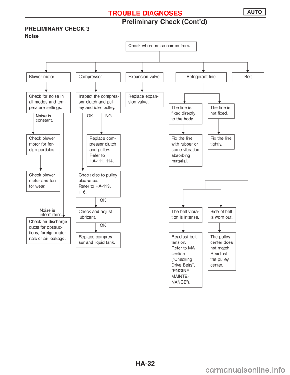
PRELIMINARY CHECK 3
Noise
Check where noise comes from.
Blower motorCompressorExpansion valveRefrigerant lineBelt
Check for noise in
all modes and tem-
perature settings.
Noise is
constant.Inspect the compres-
sor clutch and pul-
ley and idler pulley.OK NGReplace expan-
sion valve.
The line is
fixed directly
to the body.The line is
not fixed.
Check blower
motor for for-
eign particles.Replace com-
pressor clutch
and pulley.
Refer to
HA-111, 114.Fix the line
with rubber or
some vibration
absorbing
material.Fix the line
tightly.
Check blower
motor and fan
for wear.Check disc-to-pulley
clearance.
Refer to HA-113,
116.
OK
Noise is
intermittent.
Check air discharge
ducts for obstruc-
tions, foreign mate-
rials or air leakage.Check and adjust
lubricant.
OKThe belt vibra-
tion is intense.
Side of belt
is worn out.
Replace compres-
sor and liquid tank.Readjust belt
tension.
Refer to MA
section
(ªChecking
Drive Beltsº,
ªENGINE
MAINTE-
NANCEº).The pulley
center does
not match.
Readjust
the pulley
center.
HHHHH
HHH
HH
HHHH
HH
H
HHH
HHH
TROUBLE DIAGNOSESAUTO
Preliminary Check (Cont'd)
HA-32
Page 1882 of 2267
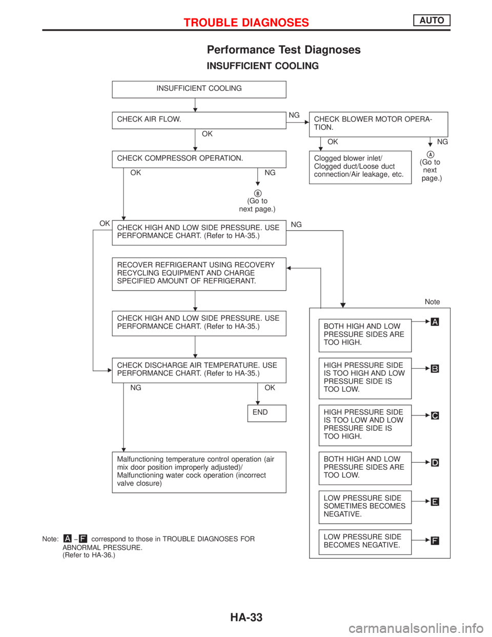
Performance Test Diagnoses
INSUFFICIENT COOLING
INSUFFICIENT COOLING
CHECK AIR FLOW.
OK
ENG
CHECK BLOWER MOTOR OPERA-
TION.
OK NG
CHECK COMPRESSOR OPERATION.
OK NGClogged blower inlet/
Clogged duct/Loose duct
connection/Air leakage, etc.
pA(Go to
next
page.)
pB(Go to
next page.)
OK
CHECK HIGH AND LOW SIDE PRESSURE. USE
PERFORMANCE CHART. (Refer to HA-35.)NG
H RECOVER REFRIGERANT USING RECOVERY
RECYCLING EQUIPMENT AND CHARGE
SPECIFIED AMOUNT OF REFRIGERANT.
F
Note
CHECK HIGH AND LOW SIDE PRESSURE. USE
PERFORMANCE CHART. (Refer to HA-35.)
BOTH HIGH AND LOW
PRESSURE SIDES ARE
TOO HIGH.E
ECHECK DISCHARGE AIR TEMPERATURE. USE
PERFORMANCE CHART. (Refer to HA-35.)
NG OKHIGH PRESSURE SIDE
IS TOO HIGH AND LOW
PRESSURE SIDE IS
TOO LOW.
E
ENDHIGH PRESSURE SIDE
IS TOO LOW AND LOW
PRESSURE SIDE IS
TOO HIGH.E
Malfunctioning temperature control operation (air
mix door position improperly adjusted)/
Malfunctioning water cock operation (incorrect
valve closure)BOTH HIGH AND LOW
PRESSURE SIDES ARE
TOO LOW.E
LOW PRESSURE SIDE
SOMETIMES BECOMES
NEGATIVE.E
LOW PRESSURE SIDE
BECOMES NEGATIVE.ENote:þcorrespond to those in TROUBLE DIAGNOSES FOR
ABNORMAL PRESSURE.
(Refer to HA-36.)
H
HHH
H
H
H
H
H
H
TROUBLE DIAGNOSESAUTO
HA-33
Page 1883 of 2267
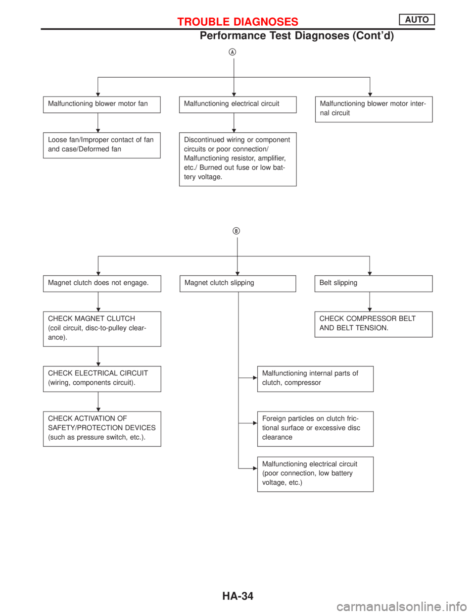
pA
Malfunctioning blower motor fanMalfunctioning electrical circuitMalfunctioning blower motor inter-
nal circuit
Loose fan/Improper contact of fan
and case/Deformed fanDiscontinued wiring or component
circuits or poor connection/
Malfunctioning resistor, amplifier,
etc./ Burned out fuse or low bat-
tery voltage.
pB
Magnet clutch does not engage.Magnet clutch slippingBelt slipping
CHECK MAGNET CLUTCH
(coil circuit, disc-to-pulley clear-
ance).CHECK COMPRESSOR BELT
AND BELT TENSION.
CHECK ELECTRICAL CIRCUIT
(wiring, components circuit).EMalfunctioning internal parts of
clutch, compressor
CHECK ACTIVATION OF
SAFETY/PROTECTION DEVICES
(such as pressure switch, etc.).EForeign particles on clutch fric-
tional surface or excessive disc
clearance
EMalfunctioning electrical circuit
(poor connection, low battery
voltage, etc.)
HHH
HH
HHH
HH
H
H
TROUBLE DIAGNOSESAUTO
Performance Test Diagnoses (Cont'd)
HA-34
Page 1884 of 2267
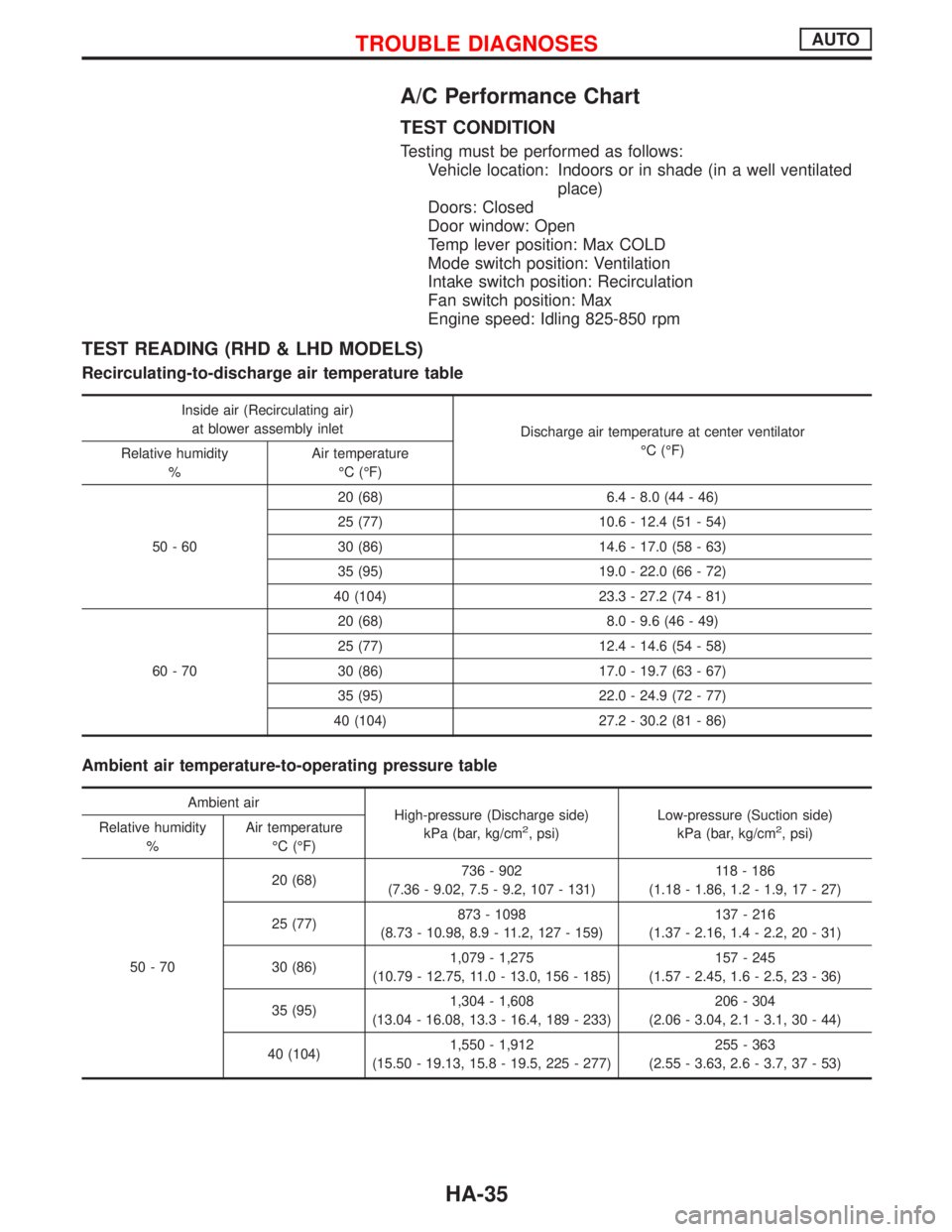
A/C Performance Chart
TEST CONDITION
Testing must be performed as follows:
Vehicle location: Indoors or in shade (in a well ventilated
place)
Doors: Closed
Door window: Open
Temp lever position: Max COLD
Mode switch position: Ventilation
Intake switch position: Recirculation
Fan switch position: Max
Engine speed: Idling 825-850 rpm
TEST READING (RHD & LHD MODELS)
Recirculating-to-discharge air temperature table
Inside air (Recirculating air)
at blower assembly inlet
Discharge air temperature at center ventilator
ÉC (ÉF)
Relative humidity
%Air temperature
ÉC (ÉF)
50-6020 (68) 6.4 - 8.0 (44 - 46)
25 (77) 10.6 - 12.4 (51 - 54)
30 (86) 14.6 - 17.0 (58 - 63)
35 (95) 19.0 - 22.0 (66 - 72)
40 (104) 23.3 - 27.2 (74 - 81)
60-7020 (68) 8.0 - 9.6 (46 - 49)
25 (77) 12.4 - 14.6 (54 - 58)
30 (86) 17.0 - 19.7 (63 - 67)
35 (95) 22.0 - 24.9 (72 - 77)
40 (104) 27.2 - 30.2 (81 - 86)
Ambient air temperature-to-operating pressure table
Ambient air
High-pressure (Discharge side)
kPa (bar, kg/cm
2, psi)Low-pressure (Suction side)
kPa (bar, kg/cm2, psi) Relative humidity
%Air temperature
ÉC (ÉF)
50-7020 (68)736 - 902
(7.36 - 9.02, 7.5 - 9.2, 107 - 131)118 - 186
(1.18 - 1.86, 1.2 - 1.9, 17 - 27)
25 (77)873 - 1098
(8.73 - 10.98, 8.9 - 11.2, 127 - 159)137 - 216
(1.37 - 2.16, 1.4 - 2.2, 20 - 31)
30 (86)1,079 - 1,275
(10.79 - 12.75, 11.0 - 13.0, 156 - 185)157 - 245
(1.57 - 2.45, 1.6 - 2.5, 23 - 36)
35 (95)1,304 - 1,608
(13.04 - 16.08, 13.3 - 16.4, 189 - 233)206 - 304
(2.06 - 3.04, 2.1 - 3.1, 30 - 44)
40 (104)1,550 - 1,912
(15.50 - 19.13, 15.8 - 19.5, 225 - 277)255 - 363
(2.55 - 3.63, 2.6 - 3.7, 37 - 53)
TROUBLE DIAGNOSESAUTO
HA-35
Page 1885 of 2267
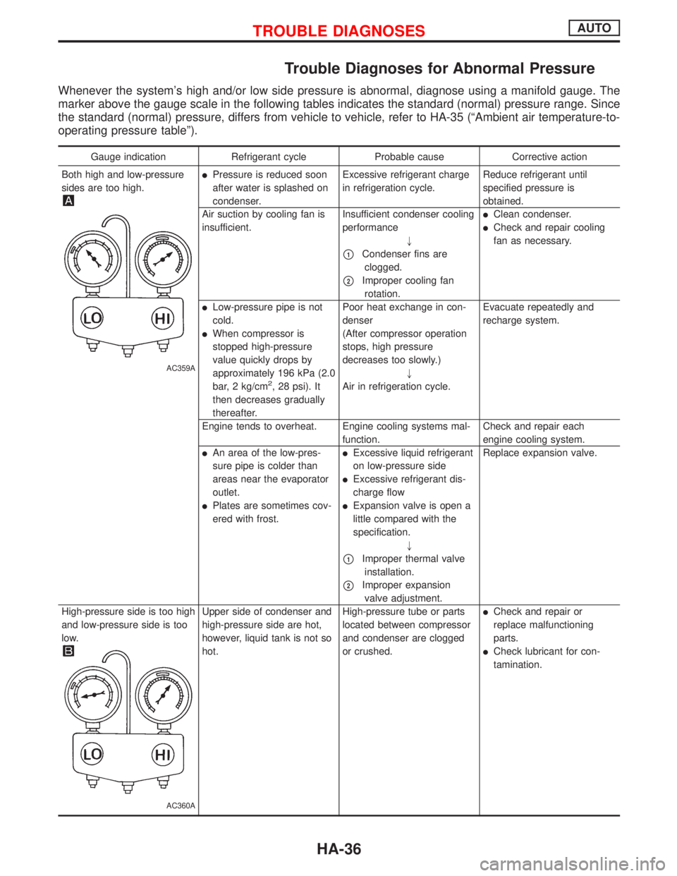
Trouble Diagnoses for Abnormal Pressure
Whenever the system's high and/or low side pressure is abnormal, diagnose using a manifold gauge. The
marker above the gauge scale in the following tables indicates the standard (normal) pressure range. Since
the standard (normal) pressure, differs from vehicle to vehicle, refer to HA-35 (ªAmbient air temperature-to-
operating pressure tableº).
Gauge indication Refrigerant cycle Probable cause Corrective action
Both high and low-pressure
sides are too high.
AC359A
lPressure is reduced soon
after water is splashed on
condenser.Excessive refrigerant charge
in refrigeration cycle.Reduce refrigerant until
specified pressure is
obtained.
Air suction by cooling fan is
insufficient.Insufficient condenser cooling
performance
"
p1Condenser fins are
clogged.
p2Improper cooling fan
rotation.
lClean condenser.
lCheck and repair cooling
fan as necessary.
lLow-pressure pipe is not
cold.
lWhen compressor is
stopped high-pressure
value quickly drops by
approximately 196 kPa (2.0
bar, 2 kg/cm
2, 28 psi). It
then decreases gradually
thereafter.Poor heat exchange in con-
denser
(After compressor operation
stops, high pressure
decreases too slowly.)
"
Air in refrigeration cycle.Evacuate repeatedly and
recharge system.
Engine tends to overheat. Engine cooling systems mal-
function.Check and repair each
engine cooling system.
lAn area of the low-pres-
sure pipe is colder than
areas near the evaporator
outlet.
lPlates are sometimes cov-
ered with frost.
lExcessive liquid refrigerant
on low-pressure side
lExcessive refrigerant dis-
charge flow
lExpansion valve is open a
little compared with the
specification.
"
p1Improper thermal valve
installation.
p2Improper expansion
valve adjustment.Replace expansion valve.
High-pressure side is too high
and low-pressure side is too
low.
AC360A
Upper side of condenser and
high-pressure side are hot,
however, liquid tank is not so
hot.High-pressure tube or parts
located between compressor
and condenser are clogged
or crushed.lCheck and repair or
replace malfunctioning
parts.
lCheck lubricant for con-
tamination.
TROUBLE DIAGNOSESAUTO
HA-36
Page 1886 of 2267
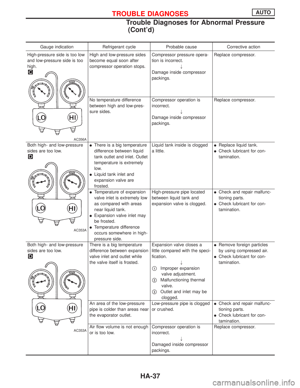
Gauge indication Refrigerant cycle Probable cause Corrective action
High-pressure side is too low
and low-pressure side is too
high.
AC356A
High and low-pressure sides
become equal soon after
compressor operation stops.Compressor pressure opera-
tion is incorrect.
"
Damage inside compressor
packings.Replace compressor.
No temperature difference
between high and low-pres-
sure sides.Compressor operation is
incorrect.
"
Damage inside compressor
packings.Replace compressor.
Both high- and low-pressure
sides are too low.
AC353A
lThere is a big temperature
difference between liquid
tank outlet and inlet. Outlet
temperature is extremely
low.
lLiquid tank inlet and
expansion valve are
frosted.Liquid tank inside is clogged
a little.
lReplace liquid tank.
lCheck lubricant for con-
tamination.
lTemperature of expansion
valve inlet is extremely low
as compared with areas
near liquid tank.
lExpansion valve inlet may
be frosted.
lTemperature difference
occurs somewhere in high-
pressure side.High-pressure pipe located
between liquid tank and
expansion valve is clogged.
lCheck and repair malfunc-
tioning parts.
lCheck lubricant for con-
tamination.
Both high- and low-pressure
sides are too low.
AC353A
There is a big temperature
difference between expansion
valve inlet and outlet while
the valve itself is frosted.Expansion valve closes a
little compared with the speci-
fication.
"
p1Improper expansion
valve adjustment.
p2Malfunctioning thermal
valve.
p3Outlet and inlet may be
clogged.
lRemove foreign particles
by using compressed air.
lCheck lubricant for con-
tamination.
An area of the low-pressure
pipe is colder than areas near
the evaporator outlet.Low-pressure pipe is clogged
or crushed.
lCheck and repair malfunc-
tioning parts.
lCheck lubricant for con-
tamination.
Air flow volume is not enough
or is too low.Compressor operation is
incorrect.
"
Damaged inside compressor
packings.Replace compressor.
TROUBLE DIAGNOSESAUTO
Trouble Diagnoses for Abnormal Pressure
(Cont'd)
HA-37
Page 1887 of 2267
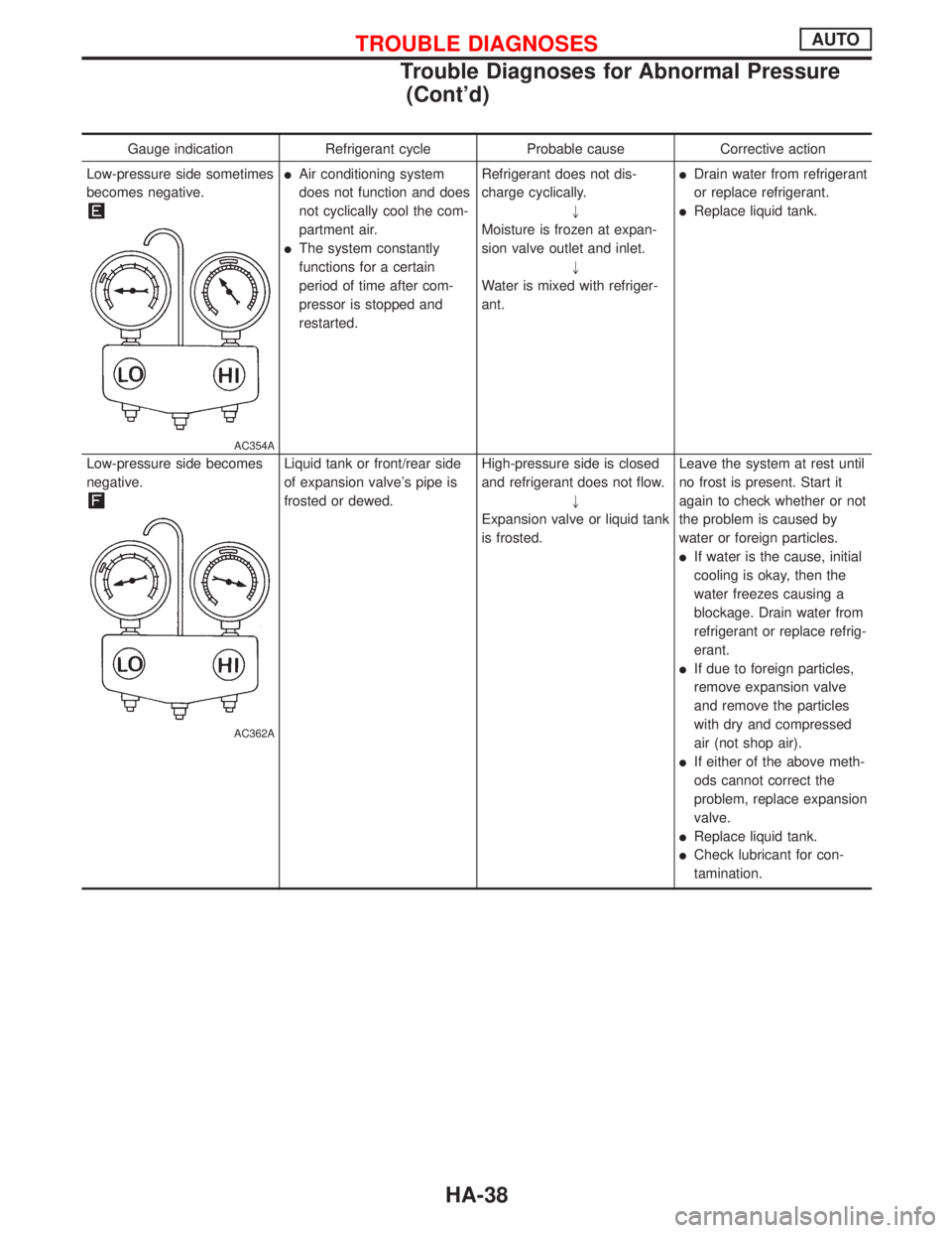
Gauge indication Refrigerant cycle Probable cause Corrective action
Low-pressure side sometimes
becomes negative.
AC354A
lAir conditioning system
does not function and does
not cyclically cool the com-
partment air.
lThe system constantly
functions for a certain
period of time after com-
pressor is stopped and
restarted.Refrigerant does not dis-
charge cyclically.
"
Moisture is frozen at expan-
sion valve outlet and inlet.
"
Water is mixed with refriger-
ant.
lDrain water from refrigerant
or replace refrigerant.
lReplace liquid tank.
Low-pressure side becomes
negative.
AC362A
Liquid tank or front/rear side
of expansion valve's pipe is
frosted or dewed.High-pressure side is closed
and refrigerant does not flow.
"
Expansion valve or liquid tank
is frosted.Leave the system at rest until
no frost is present. Start it
again to check whether or not
the problem is caused by
water or foreign particles.
lIf water is the cause, initial
cooling is okay, then the
water freezes causing a
blockage. Drain water from
refrigerant or replace refrig-
erant.
lIf due to foreign particles,
remove expansion valve
and remove the particles
with dry and compressed
air (not shop air).
lIf either of the above meth-
ods cannot correct the
problem, replace expansion
valve.
lReplace liquid tank.
lCheck lubricant for con-
tamination.
TROUBLE DIAGNOSESAUTO
Trouble Diagnoses for Abnormal Pressure
(Cont'd)
HA-38
Page 1888 of 2267
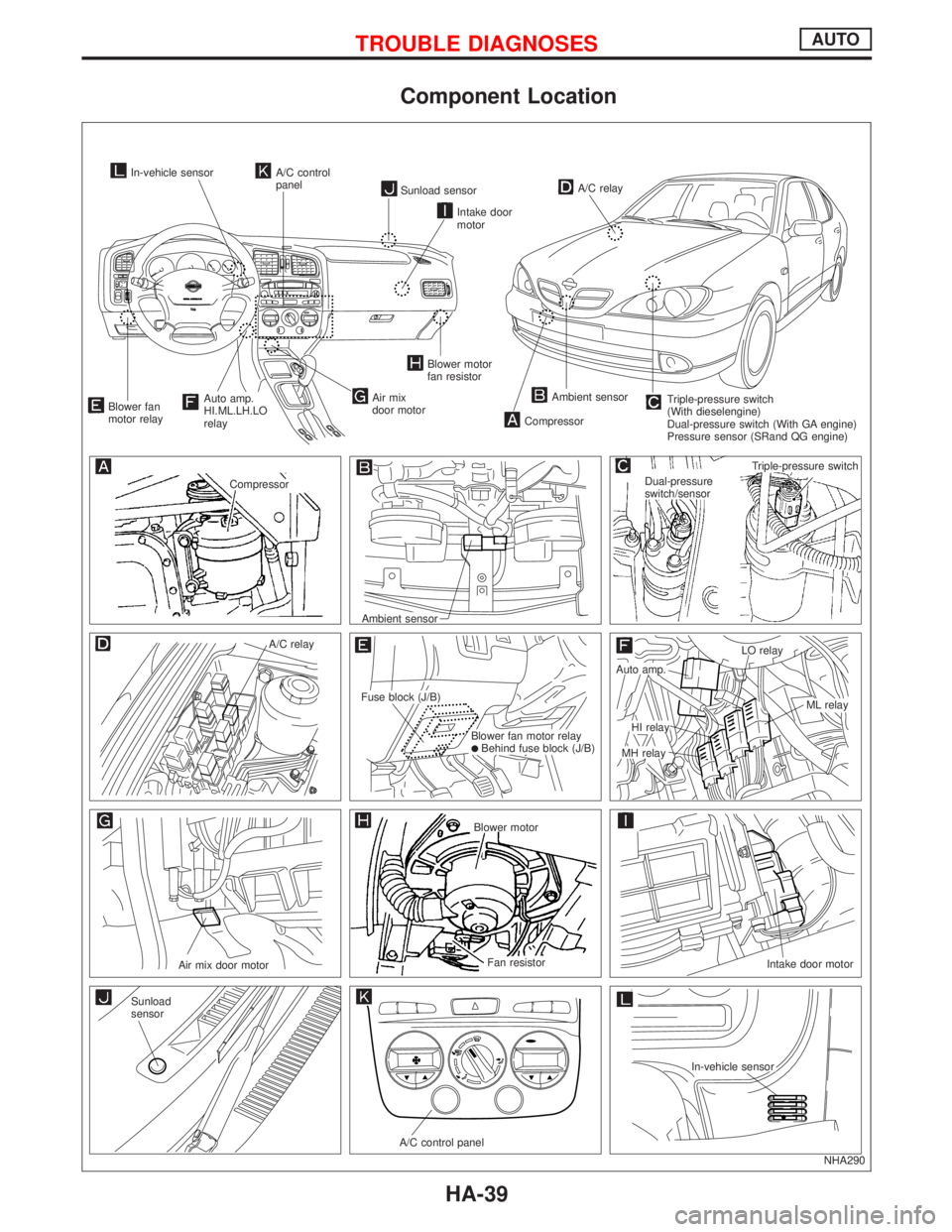
Component Location
NHA290
In-vehicle sensorA/C control
panel
Sunload sensorA/C relay
.Triple-pressure switch
(With dieselengine)
Dual-pressure switch (With GA engine)
Pressure sensor (SRand QG engine)Ambient sensor
Compressor
Blower motor
fan resistor
.Auto amp.
HI.ML.LH.LO
relayBlower fan
motor relay
Compressor
.Ambient sensor
.
A/C relay
.Fuse block (J/B)
.Blower fan motor relaylBehind fuse block (J/B)
.
.Auto amp.
.MH relayLO relay
.ML relay.HI relay
Air mix door motor
Blower motor
Fan resistor.
Intake door motor
Sunload
sensor.
A/C control panel
.
.In-vehicle sensor
.Dual-pressure
switch/sensor
.Triple-pressure switch
Intake door
motor
Air mix
door motor
TROUBLE DIAGNOSESAUTO
HA-39
Page 1889 of 2267
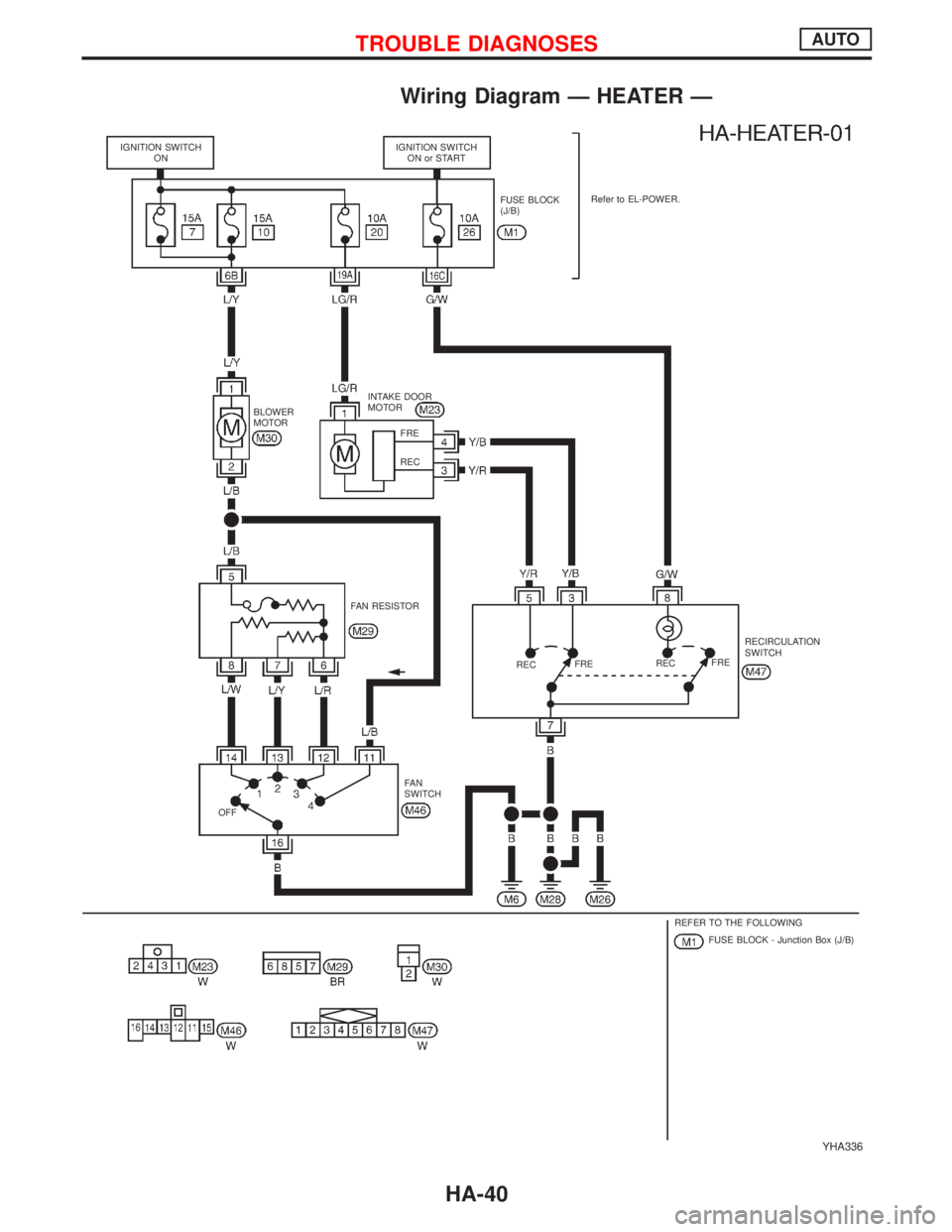
Wiring Diagram Ð HEATER Ð
YHA336
IGNITION SWITCH
ONIGNITION SWITCH
ON or START
FUSE BLOCK
(J/B)Refer to EL-POWER.
INTAKE DOOR
MOTOR
BLOWER
MOTOR
FAN RESISTOR
RECFRERECFRERECIRCULATION
SWITCH
FA N
SWITCH
OFF
REFER TO THE FOLLOWING
FUSE BLOCK - Junction Box (J/B) FRE
REC
TROUBLE DIAGNOSESAUTO
HA-40
Page 1890 of 2267
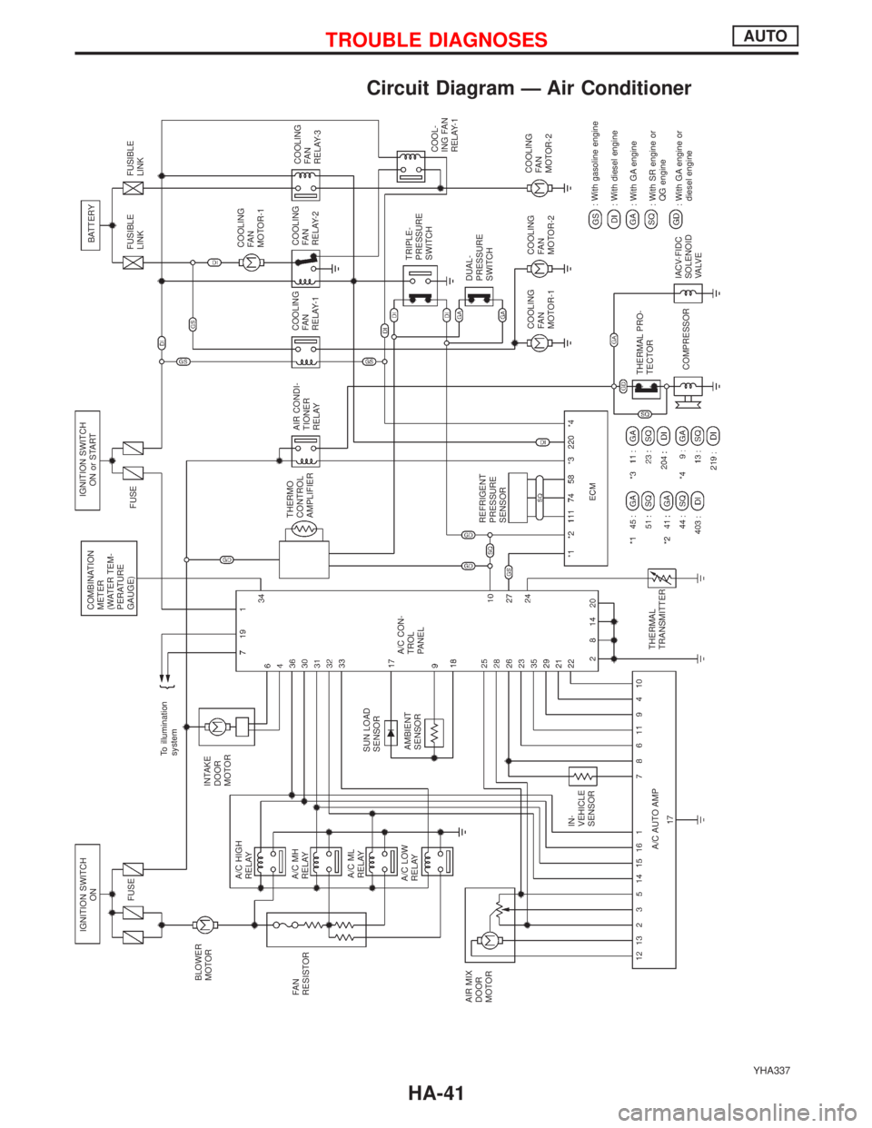
Circuit Diagram Ð Air Conditioner
YHA337
IGNITION SWITCH
ON
FUSE
BLOWER
MOTORINTAKE
DOOR
MOTORTo illumination
systemCOMBINATION
METER
(WATER TEM-
PERATURE
GAUGE)IGNITION SWITCH
ON or START
FUSEFUSIBLE
LINKBATTERY
FUSIBLE
LINK
COOLING
FA N
MOTOR-1
THERMO
CONTROL
AMPLIFIERAIR CONDI-
TIONER
RELAYCOOLING
FA N
RELAY-1COOLING
FA N
RELAY-2COOLING
FA N
RELAY-3
TRIPLE-
PRESSURE
SWITCH
COOL-
ING FAN
RELAY-1
DUAL-
PRESSURE
SWITCH
COOLING
FA N
MOTOR-1COOLING
FA N
MOTOR-2COOLING
FA N
MOTOR-2
: With gasoline engine
: With diesel engine
: With GA engine
: With SR engine or
QG engine
: With GA engine or
diesel engine IACV-FIDC
SOLENOID
VA LV E THERMAL PRO-
TECTOR
COMPRESSOR THERMAL
TRANSMITTER A/C AUTO AMPIN-
VEHICLE
SENSORA/C CON-
TROL
PANEL
REFRIGENT
PRESSURE
SENSOR AMBIENT
SENSOR SUN LOAD
SENSOR A/C HIGH
RELAY
A/C MH
RELAY
A/C ML
RELAY
A/C LOW
RELAY FA N
RESISTOR
AIR MIX
DOOR
MOTOR
TROUBLE DIAGNOSESAUTO
HA-41