NISSAN PRIMERA 1999 Electronic Repair Manual
Manufacturer: NISSAN, Model Year: 1999, Model line: PRIMERA, Model: NISSAN PRIMERA 1999Pages: 2267, PDF Size: 35.74 MB
Page 1921 of 2267
pB
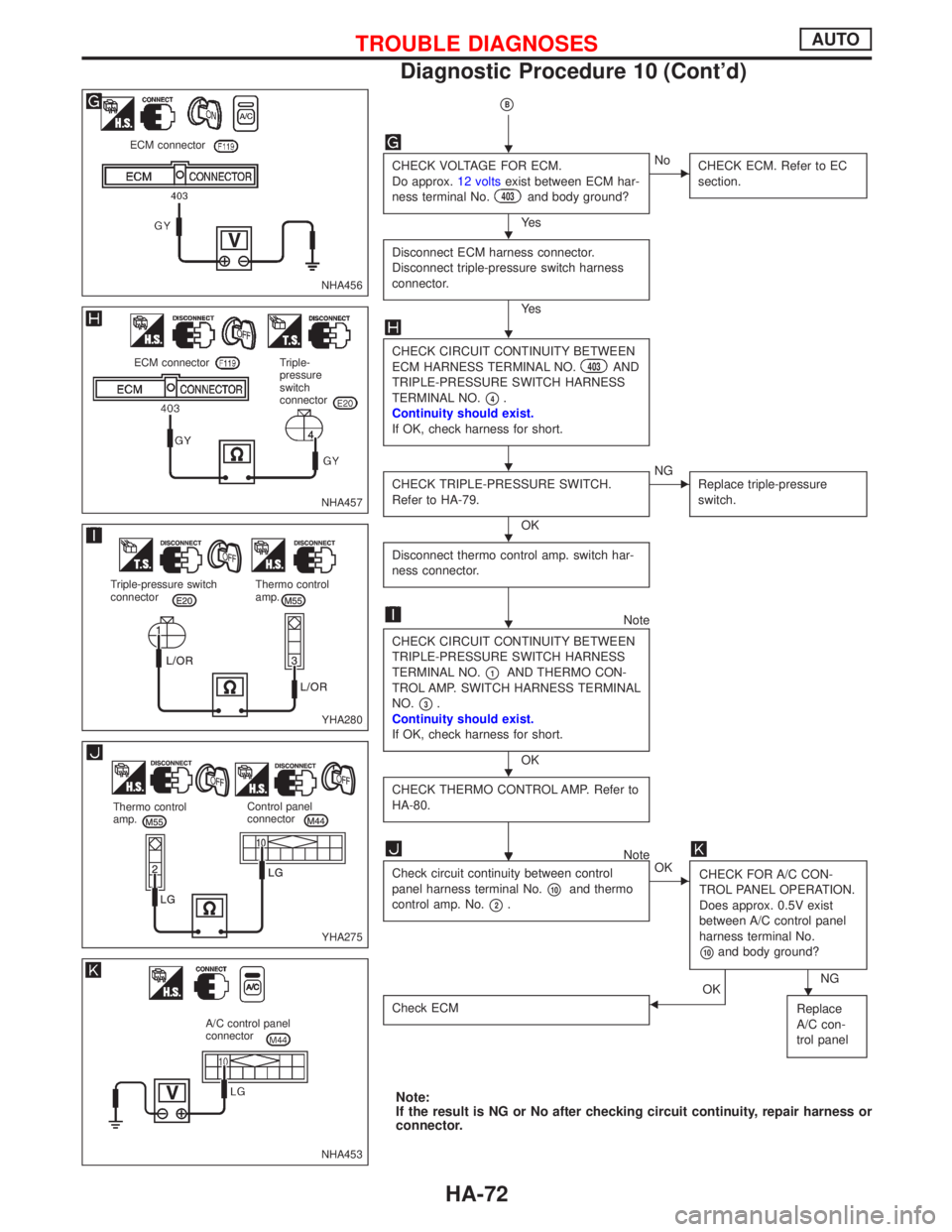
CHECK VOLTAGE FOR ECM.
Do approx.12 voltsexist between ECM har-
ness terminal No.
403and body ground?
Ye s
ENo
CHECK ECM. Refer to EC
section.
Disconnect ECM harness connector.
Disconnect triple-pressure switch harness
connector.
Ye s
CHECK CIRCUIT CONTINUITY BETWEEN
ECM HARNESS TERMINAL NO.403AND
TRIPLE-PRESSURE SWITCH HARNESS
TERMINAL NO.
p4.
Continuity should exist.
If OK, check harness for short.
CHECK TRIPLE-PRESSURE SWITCH.
Refer to HA-79.
OK
ENG
Replace triple-pressure
switch.
Disconnect thermo control amp. switch har-
ness connector.
Note
CHECK CIRCUIT CONTINUITY BETWEEN
TRIPLE-PRESSURE SWITCH HARNESS
TERMINAL NO.
p1AND THERMO CON-
TROL AMP. SWITCH HARNESS TERMINAL
NO.
p3.
Continuity should exist.
If OK, check harness for short.
OK
CHECK THERMO CONTROL AMP. Refer to
HA-80.
Note
Check circuit continuity between control
panel harness terminal No.
p10and thermo
control amp. No.
p2.
EOK
CHECK FOR A/C CON-
TROL PANEL OPERATION.
Does approx. 0.5V exist
between A/C control panel
harness terminal No.
p10and body ground?
NGOK
Check ECMFReplace
A/C con-
trol panel
Note:
If the result is NG or No after checking circuit continuity, repair harness or
connector.
NHA456
ECM connector
NHA457
ECM connector Triple-
pressure
switch
connector
YHA280
Triple-pressure switch
connectorThermo control
amp.
YHA275
Thermo control
amp.Control panel
connector
NHA453
A/C control panel
connector
H
H
H
H
H
H
H
HH
H
TROUBLE DIAGNOSESAUTO
Diagnostic Procedure 10 (Cont'd)
HA-72
Page 1922 of 2267
pC
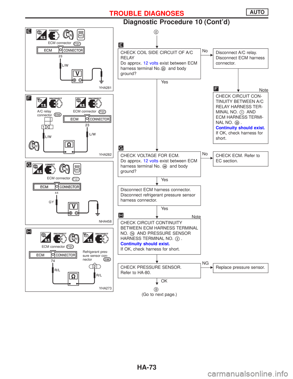
CHECK COIL SIDE CIRCUIT OF A/C
RELAY
Do approx.12 voltsexist between ECM
harness terminal No.
p23and body
ground?
Ye s
ENo
Disconnect A/C relay.
Disconnect ECM harness
connector.
Note
CHECK CIRCUIT CON-
TINUITY BETWEEN A/C
RELAY HARNESS TER-
MINAL NO.
p1AND
ECM HARNESS TERMI-
NAL NO.
p23.
Continuity should exist.
If OK, check harness for
short.
CHECK VOLTAGE FOR ECM.
Do approx.12 voltsexist between ECM
harness terminal No.
p44and body
ground?
Ye s
ENo
CHECK ECM. Refer to
EC section.
Disconnect ECM harness connector.
Disconnect refrigerant pressure sensor
harness connector.
Ye s
Note
CHECK CIRCUIT CONTINUITY
BETWEEN ECM HARNESS TERMINAL
NO.
p74AND PRESSURE SENSOR
HARNESS TERMINAL NO.
p2.
Continuity should exist.
If OK, check harness for short.
CHECK PRESSURE SENSOR.
Refer to HA-80.
OK
ENG
Replace pressure sensor.
pD
(Go to next page.)
YHA281
ECM connector
YHA282
A/C relay
connectorECM connector
NHA458
ECM connector
YHA273
ECM connector
Refrigerant pres-
sure sensor con-
nector
H
H
H
H
H
H
H
TROUBLE DIAGNOSESAUTO
Diagnostic Procedure 10 (Cont'd)
HA-73
Page 1923 of 2267
pD
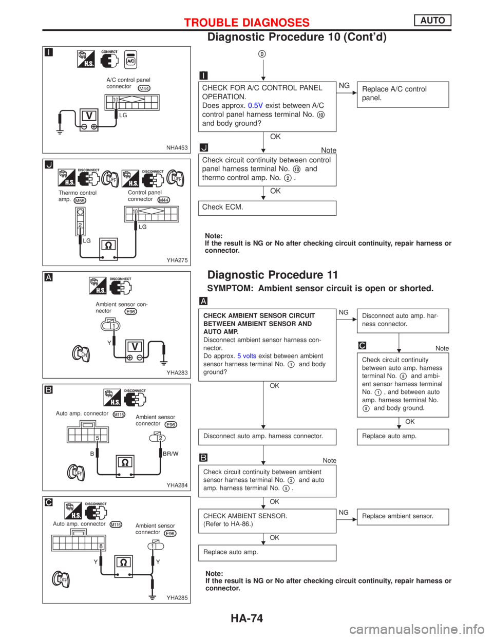
CHECK FOR A/C CONTROL PANEL
OPERATION.
Does approx.0.5Vexist between A/C
control panel harness terminal No.
p10
and body ground?
OK
ENG
Replace A/C control
panel.
Note
Check circuit continuity between control
panel harness terminal No.
p10and
thermo control amp. No.
p2.
OK
Check ECM.
Note:
If the result is NG or No after checking circuit continuity, repair harness or
connector.
Diagnostic Procedure 11
SYMPTOM: Ambient sensor circuit is open or shorted.
CHECK AMBIENT SENSOR CIRCUIT
BETWEEN AMBIENT SENSOR AND
AUTO AMP.
Disconnect ambient sensor harness con-
nector.
Do approx.5 voltsexist between ambient
sensor harness terminal No.
p1and body
ground?
OK
ENG
Disconnect auto amp. har-
ness connector.
Note
Check circuit continuity
between auto amp. harness
terminal No.
p8and ambi-
ent sensor harness terminal
No.
p1, and between auto
amp. harness terminal No.
p8and body ground.
OK
Disconnect auto amp. harness connector.
Replace auto amp.
Note
Check circuit continuity between ambient
sensor harness terminal No.
p2and auto
amp. harness terminal No.
p5.
OK
CHECK AMBIENT SENSOR.
(Refer to HA-86.)
OK
ENG
Replace ambient sensor.
Replace auto amp.
Note:
If the result is NG or No after checking circuit continuity, repair harness or
connector.
NHA453
A/C control panel
connector
YHA275
Thermo control
amp.Control panel
connector
YHA283
Ambient sensor con-
nector
YHA284
Auto amp. connector
Ambient sensor
connector
YHA285
Auto amp. connector
Ambient sensor
connector
H
H
H
H
HH
H
H
H
TROUBLE DIAGNOSESAUTO
Diagnostic Procedure 10 (Cont'd)
HA-74
Page 1924 of 2267
Diagnostic Procedure 12
SYMPTOM: In-vehicle sensor circuit is open or shorted.
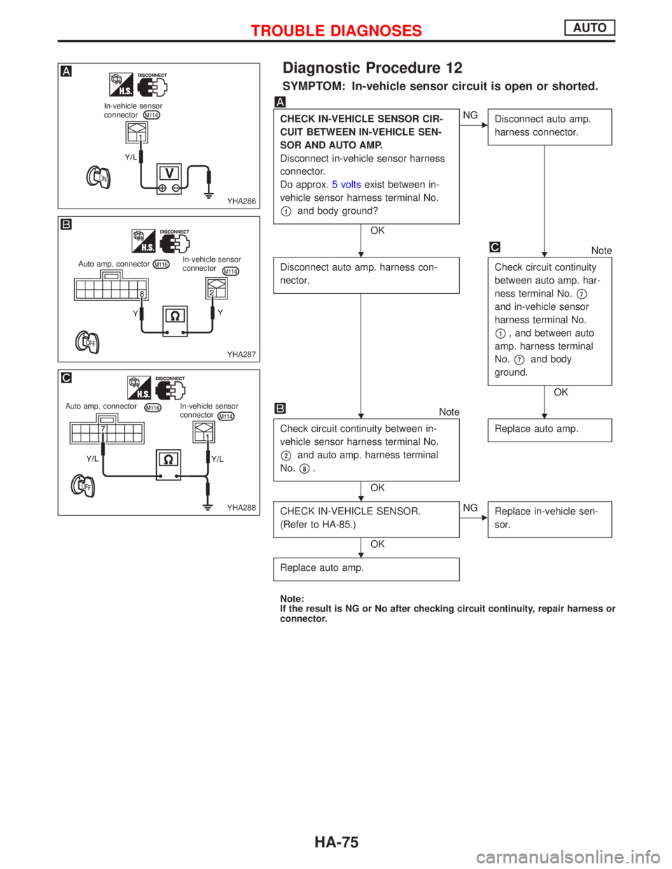
CHECK IN-VEHICLE SENSOR CIR-
CUIT BETWEEN IN-VEHICLE SEN-
SOR AND AUTO AMP.
Disconnect in-vehicle sensor harness
connector.
Do approx.5 voltsexist between in-
vehicle sensor harness terminal No.
p1and body ground?
OK
ENG
Disconnect auto amp.
harness connector.
Disconnect auto amp. harness con-
nector.
Note
Check circuit continuity
between auto amp. har-
ness terminal No.
p7
and in-vehicle sensor
harness terminal No.
p1, and between auto
amp. harness terminal
No.
p7and body
ground.
OK
Note
Check circuit continuity between in-
vehicle sensor harness terminal No.
p2and auto amp. harness terminal
No.
p8.
OKReplace auto amp.
CHECK IN-VEHICLE SENSOR.
(Refer to HA-85.)
OK
ENG
Replace in-vehicle sen-
sor.
Replace auto amp.
Note:
If the result is NG or No after checking circuit continuity, repair harness or
connector.
YHA286
In-vehicle sensor
connector
YHA287
Auto amp. connectorIn-vehicle sensor
connector
YHA288
Auto amp. connector In-vehicle sensor
connector
HH
HH
H
H
TROUBLE DIAGNOSESAUTO
HA-75
Page 1925 of 2267
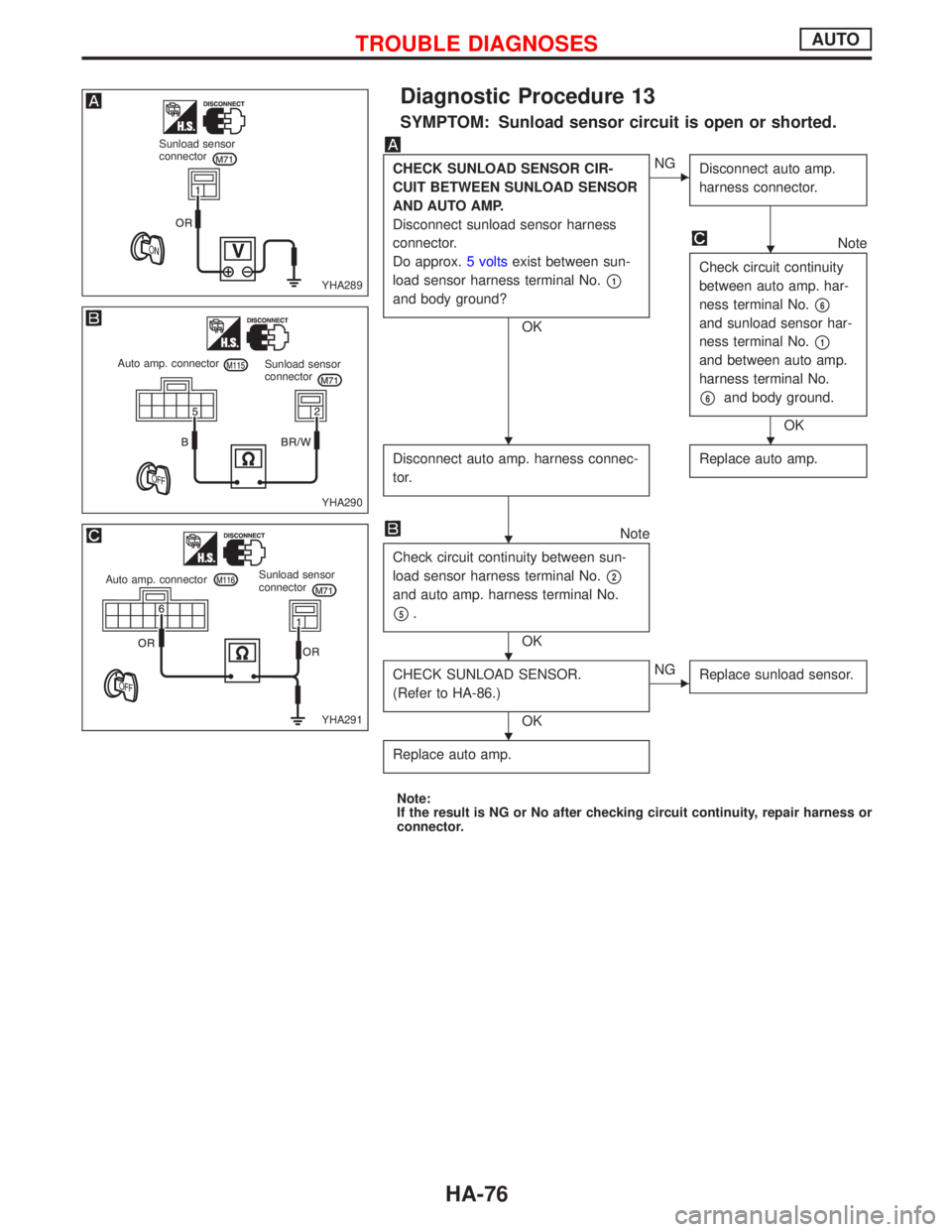
Diagnostic Procedure 13
SYMPTOM: Sunload sensor circuit is open or shorted.
CHECK SUNLOAD SENSOR CIR-
CUIT BETWEEN SUNLOAD SENSOR
AND AUTO AMP.
Disconnect sunload sensor harness
connector.
Do approx.5 voltsexist between sun-
load sensor harness terminal No.
p1
and body ground?
OK
ENG
Disconnect auto amp.
harness connector.
Note
Check circuit continuity
between auto amp. har-
ness terminal No.
p6
and sunload sensor har-
ness terminal No.
p1
and between auto amp.
harness terminal No.
p6and body ground.
OK
Disconnect auto amp. harness connec-
tor.
Replace auto amp.
Note
Check circuit continuity between sun-
load sensor harness terminal No.
p2
and auto amp. harness terminal No.
p5.
OK
CHECK SUNLOAD SENSOR.
(Refer to HA-86.)
OK
ENG
Replace sunload sensor.
Replace auto amp.
Note:
If the result is NG or No after checking circuit continuity, repair harness or
connector.
YHA289
Sunload sensor
connector
YHA290
Auto amp. connector
Sunload sensor
connector
YHA291
Auto amp. connectorSunload sensor
connector
H
HH
H
H
H
TROUBLE DIAGNOSESAUTO
HA-76
Page 1926 of 2267
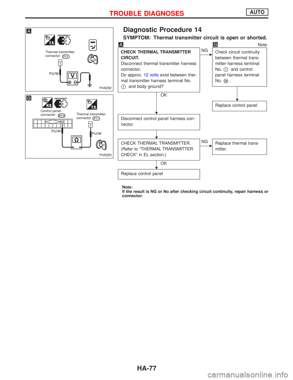
Diagnostic Procedure 14
SYMPTOM: Thermal transmitter circuit is open or shorted.
Note
CHECK THERMAL TRANSMITTER
CIRCUIT.
Disconnect thermal transmitter harness
connector.
Do approx.12 voltsexist between ther-
mal transmitter harness terminal No.
p1and body ground?
OK
ENG
Check circuit continuity
between thermal trans-
mitter harness terminal
No.
p1and control
panel harness terminal
No.
p24.
Replace control panel
Disconnect control panel harness con-
nector.
CHECK THERMAL TRANSMITTER.
(Refer to ªTHERMAL TRANSMITTER
CHECKº in EL section.)
OK
ENG
Replace thermal trans-
mitter.
Replace control panel
Note:
If the result is NG or No after checking circuit continuity, repair harness or
connector.
YHA292
Thermal transmitter
connector
YHA293
Control panel
connectorThermal transmitter
connector
H
H
H
H
TROUBLE DIAGNOSESAUTO
HA-77
Page 1927 of 2267
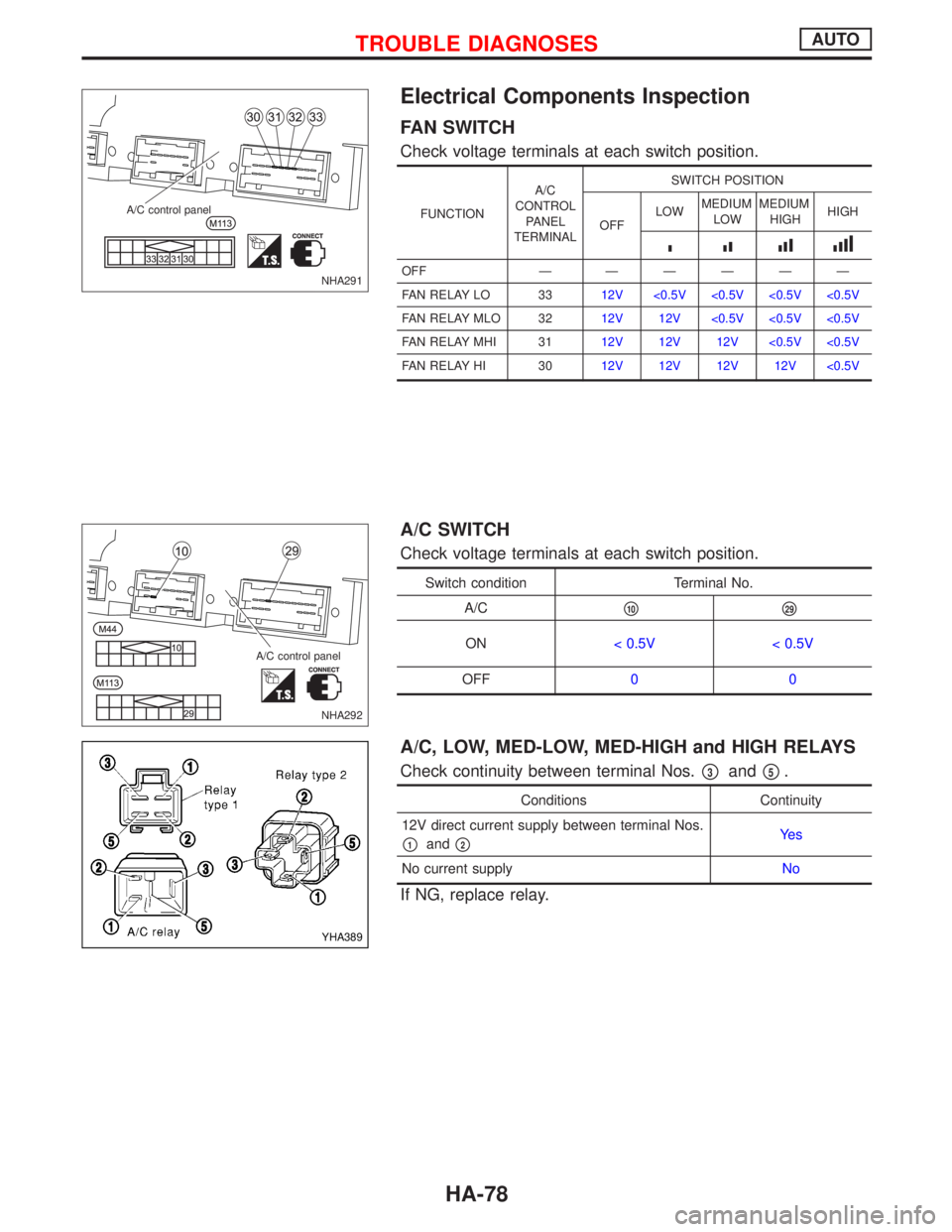
Electrical Components Inspection
FAN SWITCH
Check voltage terminals at each switch position.
FUNCTIONA/C
CONTROL
PANEL
TERMINALSWITCH POSITION
OFFLOWMEDIUM
LOWMEDIUM
HIGHHIGH
IIIIIIIIII
OFF Ð ÐÐÐÐÐ
FAN RELAY LO 3312V <0.5V <0.5V <0.5V <0.5V
FAN RELAY MLO 3212V 12V <0.5V <0.5V <0.5V
FAN RELAY MHI 3112V 12V 12V <0.5V <0.5V
FAN RELAY HI 3012V 12V 12V 12V <0.5V
A/C SWITCH
Check voltage terminals at each switch position.
Switch condition Terminal No.
A/C
p10p29
ON< 0.5V < 0.5V
OFF00
A/C, LOW, MED-LOW, MED-HIGH and HIGH RELAYS
Check continuity between terminal Nos.p3andp5.
Conditions Continuity
12V direct current supply between terminal Nos.
p1andp2Ye s
No current supplyNo
If NG, replace relay.
NHA291 A/C control panel
NHA292 A/C control panel
YHA389
TROUBLE DIAGNOSESAUTO
HA-78
Page 1928 of 2267
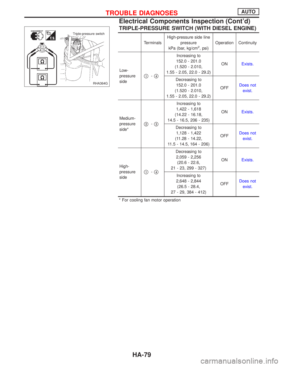
TRIPLE-PRESSURE SWITCH (WITH DIESEL ENGINE)
TerminalsHigh-pressure side line
pressure
kPa (bar, kg/cm2, psi)Operation Continuity
Low-
pressure
side
p1-p4
Increasing to
152.0 - 201.0
(1.520 - 2.010,
1.55 - 2.05, 22.0 - 29.2)ONExists.
Decreasing to
152.0 - 201.0
(1.520 - 2.010,
1.55 - 2.05, 22.0 - 29.2)OFFDoes not
exist.
Medium-
pressure
side*
p2-p3
Increasing to
1,422 - 1,618
(14.22 - 16.18,
14.5 - 16.5, 206 - 235)ONExists.
Decreasing to
1,128 - 1,422
(11.28 - 14.22,
11.5 - 14.5, 164 - 206)OFFDoes not
exist.
High-
pressure
side
p1-p4
Decreasing to
2,059 - 2,256
(20.6 - 22.6,
21 - 23, 299 - 327)ONExists.
Increasing to
2,648 - 2,844
(26.5 - 28.4,
27 - 29, 384 - 412)OFFDoes not
exist.
* For cooling fan motor operation
RHA364G
.Triple-pressure switch
TROUBLE DIAGNOSESAUTO
Electrical Components Inspection (Cont'd)
HA-79
Page 1929 of 2267
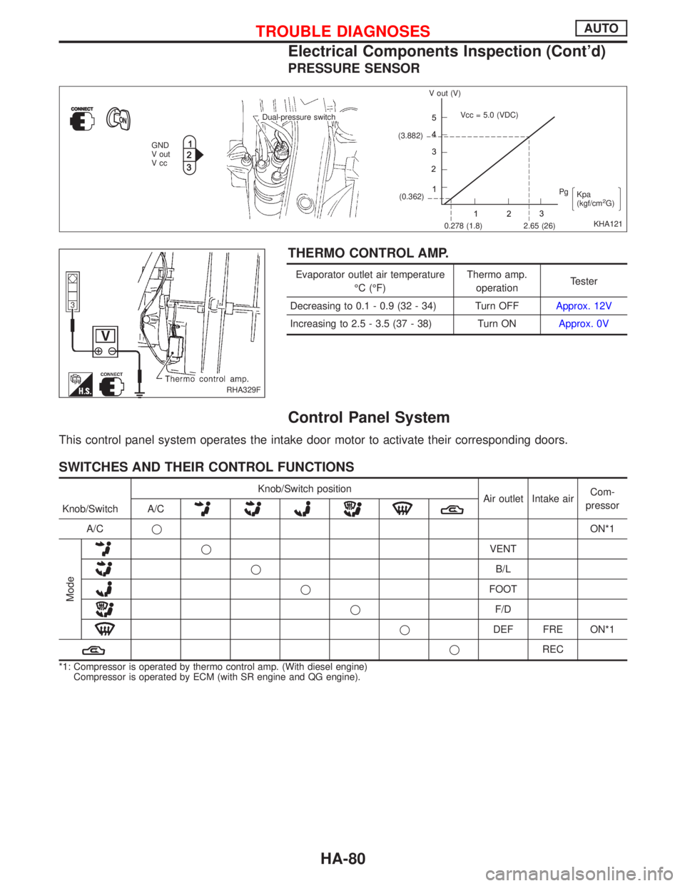
PRESSURE SENSOR
THERMO CONTROL AMP.
Evaporator outlet air temperature
ÉC (ÉF)Thermo amp.
operationTester
Decreasing to 0.1 - 0.9 (32 - 34) Turn OFFApprox. 12V
Increasing to 2.5 - 3.5 (37 - 38) Turn ONApprox. 0V
Control Panel System
This control panel system operates the intake door motor to activate their corresponding doors.
SWITCHES AND THEIR CONTROL FUNCTIONS
Knob/Switch position
Air outlet Intake airCom-
pressor
Knob/Switch A/C
A/CqON*1
Mode
qVENT
qB/L
qFOOT
qF/D
qDEF FRE ON*1
qREC
*1: Compressor is operated by thermo control amp. (With diesel engine)
Compressor is operated by ECM (with SR engine and QG engine).
KHA121 Dual-pressure switch
GND
V out
VccV out (V)
(3.882)
(0.362)Vcc = 5.0 (VDC)
0.278 (1.8) 2.65 (26)Pg
Kpa
(kgf/cm
2G)
RHA329F
TROUBLE DIAGNOSESAUTO
Electrical Components Inspection (Cont'd)
HA-80
Page 1930 of 2267
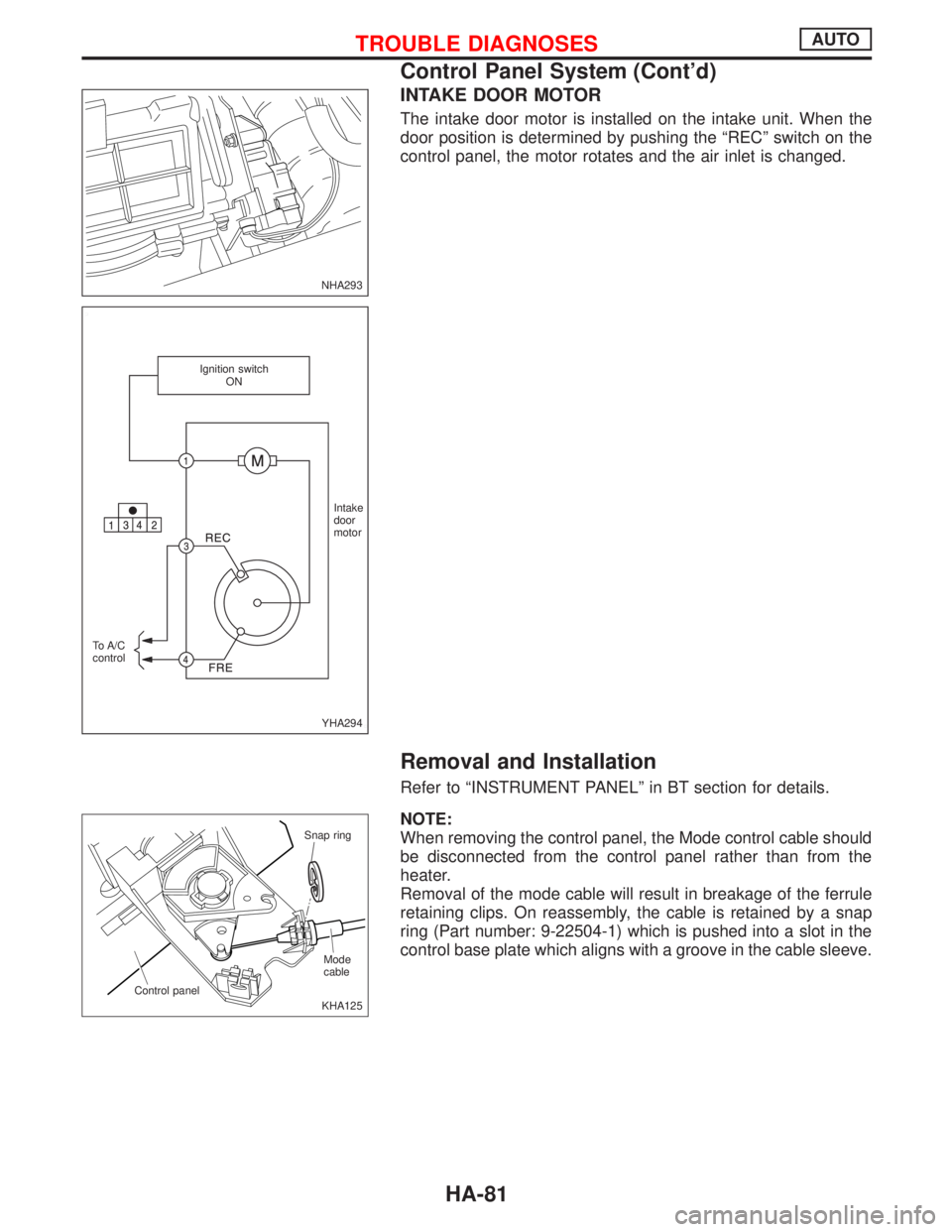
INTAKE DOOR MOTOR
The intake door motor is installed on the intake unit. When the
door position is determined by pushing the ªRECº switch on the
control panel, the motor rotates and the air inlet is changed.
Removal and Installation
Refer to ªINSTRUMENT PANELº in BT section for details.
NOTE:
When removing the control panel, the Mode control cable should
be disconnected from the control panel rather than from the
heater.
Removal of the mode cable will result in breakage of the ferrule
retaining clips. On reassembly, the cable is retained by a snap
ring (Part number: 9-22504-1) which is pushed into a slot in the
control base plate which aligns with a groove in the cable sleeve.
NHA293
YHA294 Ignition switch
ON
Intake
door
motor
To A/C
control
KHA125 Snap ring
Control panelMode
cable
TROUBLE DIAGNOSESAUTO
Control Panel System (Cont'd)
HA-81