NISSAN PRIMERA 1999 Electronic Repair Manual
Manufacturer: NISSAN, Model Year: 1999, Model line: PRIMERA, Model: NISSAN PRIMERA 1999Pages: 2267, PDF Size: 35.74 MB
Page 1911 of 2267
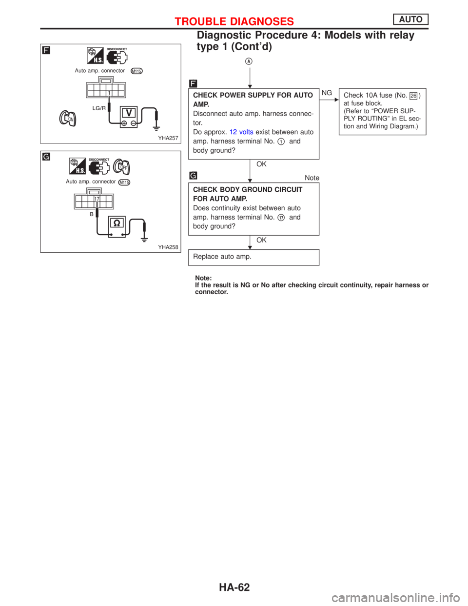
pA
CHECK POWER SUPPLY FOR AUTO
AMP.
Disconnect auto amp. harness connec-
tor.
Do approx.12 voltsexist between auto
amp. harness terminal No.
p1and
body ground?
OK
ENG
Check 10A fuse (No.26)
at fuse block.
(Refer to ªPOWER SUP-
PLY ROUTINGº in EL sec-
tion and Wiring Diagram.)
Note
CHECK BODY GROUND CIRCUIT
FOR AUTO AMP.
Does continuity exist between auto
amp. harness terminal No.
p17and
body ground?
OK
Replace auto amp.
Note:
If the result is NG or No after checking circuit continuity, repair harness or
connector.
YHA257
Auto amp. connector
YHA258
Auto amp. connector
H
H
H
TROUBLE DIAGNOSESAUTO
Diagnostic Procedure 4: Models with relay
type 1 (Cont'd)
HA-62
Page 1912 of 2267
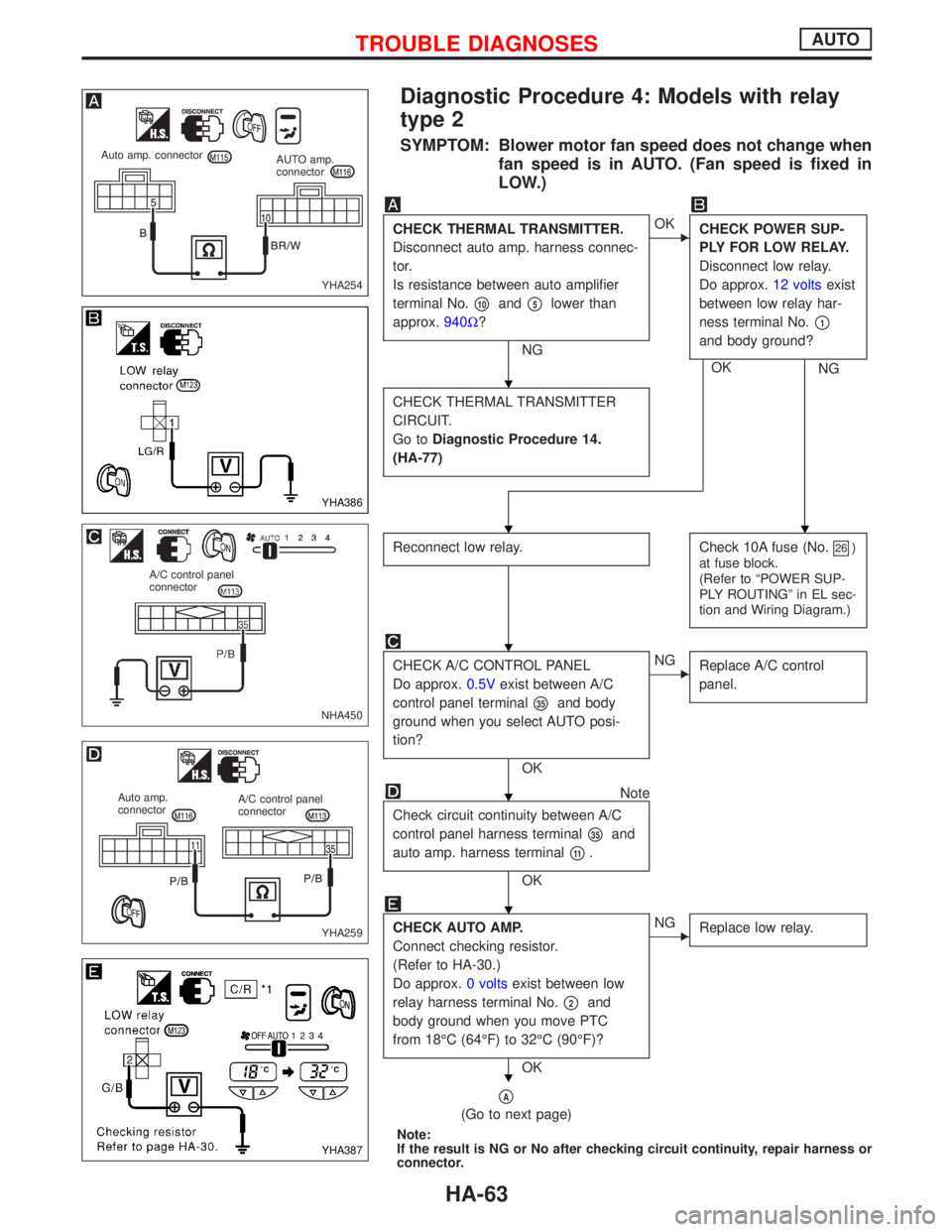
Diagnostic Procedure 4: Models with relay
type 2
SYMPTOM: Blower motor fan speed does not change when
fan speed is in AUTO. (Fan speed is fixed in
LOW.)
CHECK THERMAL TRANSMITTER.
Disconnect auto amp. harness connec-
tor.
Is resistance between auto amplifier
terminal No.
p10andp5lower than
approx.940W?
NG
EOK
CHECK POWER SUP-
PLY FOR LOW RELAY.
Disconnect low relay.
Do approx.12 voltsexist
between low relay har-
ness terminal No.
p1
and body ground?
OK
NG
CHECK THERMAL TRANSMITTER
CIRCUIT.
Go toDiagnostic Procedure 14.
(HA-77)
Reconnect low relay.Check 10A fuse (No.26)
at fuse block.
(Refer to ªPOWER SUP-
PLY ROUTINGº in EL sec-
tion and Wiring Diagram.)
CHECK A/C CONTROL PANEL
Do approx.0.5Vexist between A/C
control panel terminal
p35and body
ground when you select AUTO posi-
tion?
OK
ENG
Replace A/C control
panel.
Note
Check circuit continuity between A/C
control panel harness terminal
p35and
auto amp. harness terminal
p11.
OK
CHECK AUTO AMP.
Connect checking resistor.
(Refer to HA-30.)
Do approx.0 voltsexist between low
relay harness terminal No.
p2and
body ground when you move PTC
from 18ÉC (64ÉF) to 32ÉC (90ÉF)?
OK
ENG
Replace low relay.
pA
(Go to next page)
Note:
If the result is NG or No after checking circuit continuity, repair harness or
connector.
YHA254
Auto amp. connector
AUTO amp.
connector
YHA386
NHA450
A/C control panel
connector
YHA259
Auto amp.
connectorA/C control panel
connector
YHA387
H
HH
H
H
H
H
TROUBLE DIAGNOSESAUTO
HA-63
Page 1913 of 2267
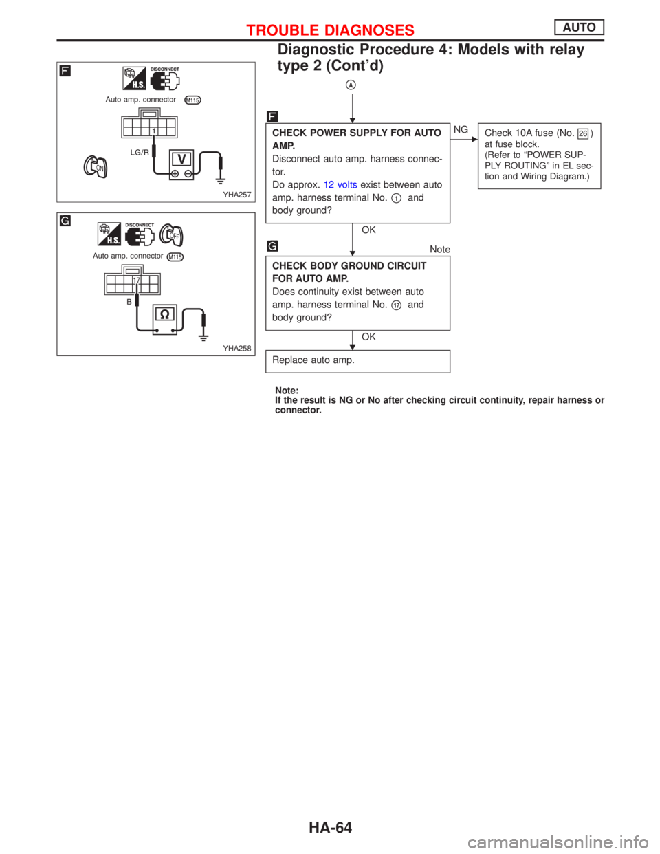
pA
CHECK POWER SUPPLY FOR AUTO
AMP.
Disconnect auto amp. harness connec-
tor.
Do approx.12 voltsexist between auto
amp. harness terminal No.
p1and
body ground?
OK
ENG
Check 10A fuse (No.26)
at fuse block.
(Refer to ªPOWER SUP-
PLY ROUTINGº in EL sec-
tion and Wiring Diagram.)
Note
CHECK BODY GROUND CIRCUIT
FOR AUTO AMP.
Does continuity exist between auto
amp. harness terminal No.
p17and
body ground?
OK
Replace auto amp.
Note:
If the result is NG or No after checking circuit continuity, repair harness or
connector.
YHA257
Auto amp. connector
YHA258
Auto amp. connector
H
H
H
TROUBLE DIAGNOSESAUTO
Diagnostic Procedure 4: Models with relay
type 2 (Cont'd)
HA-64
Page 1914 of 2267
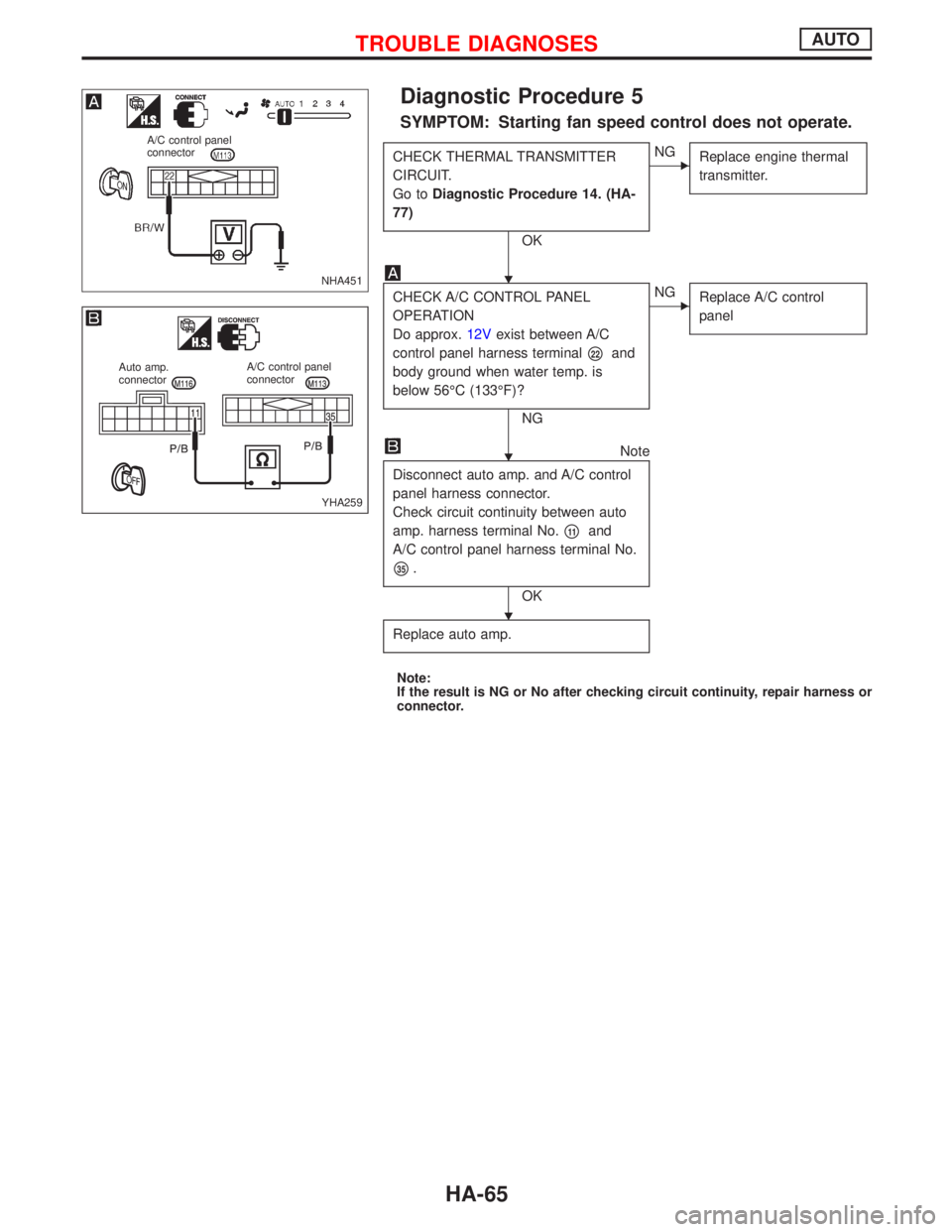
Diagnostic Procedure 5
SYMPTOM: Starting fan speed control does not operate.
CHECK THERMAL TRANSMITTER
CIRCUIT.
Go toDiagnostic Procedure 14. (HA-
77)
OK
ENG
Replace engine thermal
transmitter.
CHECK A/C CONTROL PANEL
OPERATION
Do approx.12Vexist between A/C
control panel harness terminal
p22and
body ground when water temp. is
below 56ÉC (133ÉF)?
NG
ENG
Replace A/C control
panel
Note
Disconnect auto amp. and A/C control
panel harness connector.
Check circuit continuity between auto
amp. harness terminal No.
p11and
A/C control panel harness terminal No.
p35.
OK
Replace auto amp.
Note:
If the result is NG or No after checking circuit continuity, repair harness or
connector.
NHA451
A/C control panel
connector
YHA259
Auto amp.
connectorA/C control panel
connector
H
H
H
TROUBLE DIAGNOSESAUTO
HA-65
Page 1915 of 2267
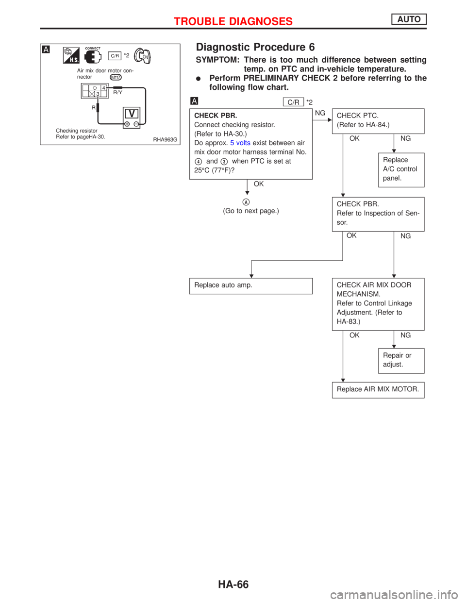
Diagnostic Procedure 6
SYMPTOM: There is too much difference between setting
temp. on PTC and in-vehicle temperature.
lPerform PRELIMINARY CHECK 2 before referring to the
following flow chart.
C/R*2
CHECK PBR.
Connect checking resistor.
(Refer to HA-30.)
Do approx.5 voltsexist between air
mix door motor harness terminal No.
p4andp3when PTC is set at
25ÉC (77ÉF)?
OK
ENG
CHECK PTC.
(Refer to HA-84.)
OK NG
Replace
A/C control
panel.
pA
(Go to next page.)CHECK PBR.
Refer to Inspection of Sen-
sor.
OK
NG
Replace auto amp.CHECK AIR MIX DOOR
MECHANISM.
Refer to Control Linkage
Adjustment. (Refer to
HA-83.)
OK NG
Repair or
adjust.
Replace AIR MIX MOTOR.
RHA963G
Air mix door motor con-
nector
Checking resistor
Refer to pageHA-30.
H
HH
HH
H
H
TROUBLE DIAGNOSESAUTO
HA-66
Page 1916 of 2267
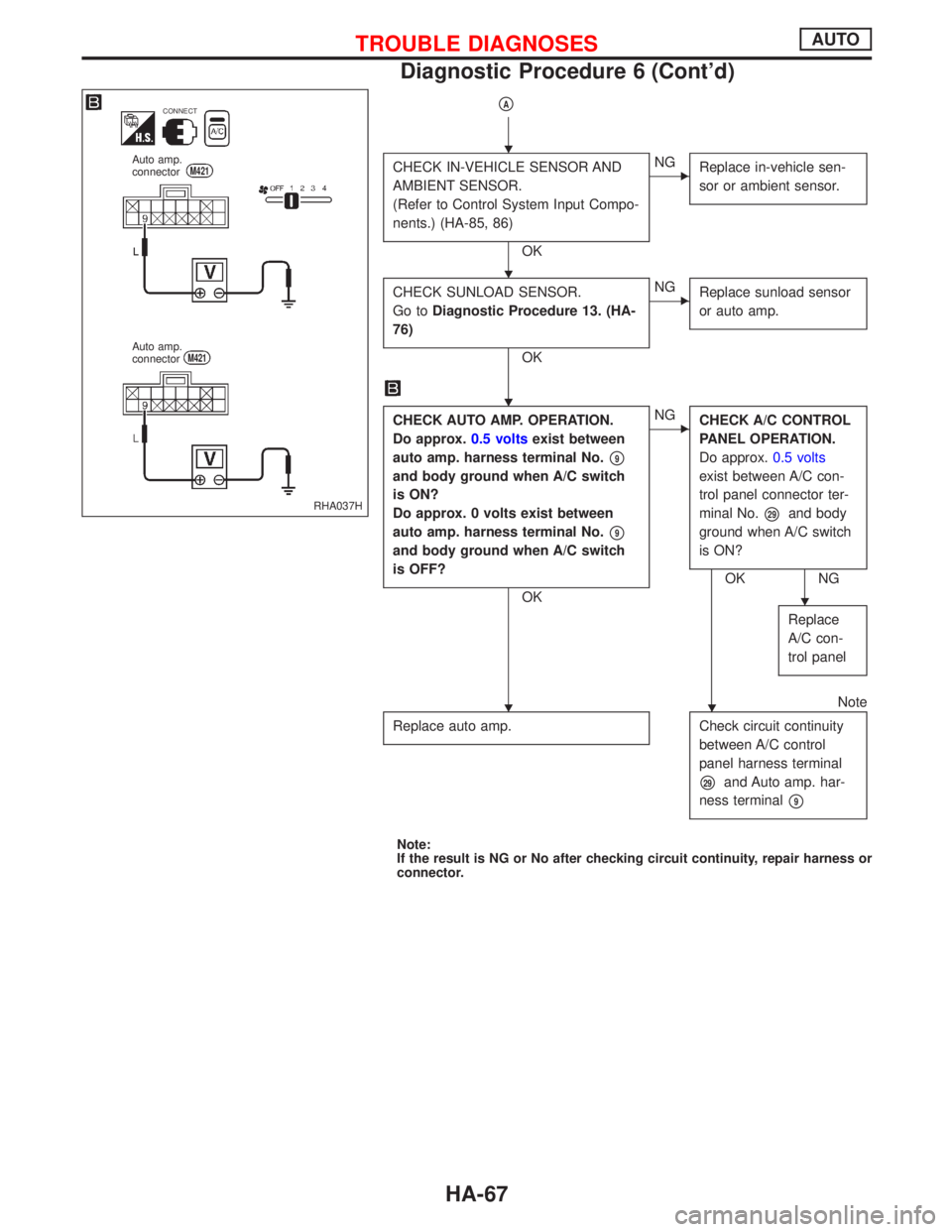
pA
CHECK IN-VEHICLE SENSOR AND
AMBIENT SENSOR.
(Refer to Control System Input Compo-
nents.) (HA-85, 86)
OK
ENG
Replace in-vehicle sen-
sor or ambient sensor.
CHECK SUNLOAD SENSOR.
Go toDiagnostic Procedure 13. (HA-
76)
OK
ENG
Replace sunload sensor
or auto amp.
CHECK AUTO AMP. OPERATION.
Do approx.0.5 voltsexist between
auto amp. harness terminal No.
p9
and body ground when A/C switch
is ON?
Do approx. 0 volts exist between
auto amp. harness terminal No.
p9
and body ground when A/C switch
is OFF?
OK
ENG
CHECK A/C CONTROL
PANEL OPERATION.
Do approx.0.5 volts
exist between A/C con-
trol panel connector ter-
minal No.
p29and body
ground when A/C switch
is ON?
OK NG
Replace
A/C con-
trol panel
Replace auto amp.
Note
Check circuit continuity
between A/C control
panel harness terminal
p29and Auto amp. har-
ness terminal
p9
Note:
If the result is NG or No after checking circuit continuity, repair harness or
connector.
RHA037H
CONNECT
Auto amp.
connectorM421
Auto amp.
connectorM421
H
H
HH
H
HH
TROUBLE DIAGNOSESAUTO
Diagnostic Procedure 6 (Cont'd)
HA-67
Page 1917 of 2267
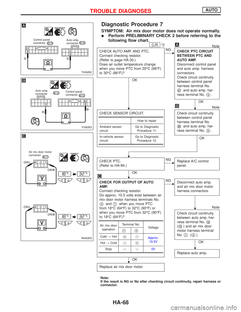
Diagnostic Procedure 7
SYMPTOM: Air mix door motor does not operate normally.
lPerform PRELIMINARY CHECK 2 before referring to the
following flow chart.
C/R*2Note
CHECK AUTO AMP. AND PTC.
Connect checking resistor.
(Refer to page HA-30.)
Does air outlet temperature change
when you move PTC from 20ÉC (68ÉF)
to 30ÉC (86ÉF)?
OK
ENG
CHECK PTC CIRCUIT
BETWEEN PTC AND
AUTO AMP.
Disconnect control panel
and auto amp. harness
connectors.
Check circuit continuity
between control panel
harness terminal No.
p21and auto amp. har-
ness terminal No.
p4.
OK
CHECK SENSOR CIRCUIT.
Note
Check circuit continuity
between control panel
harness terminal No.
p25and auto amp. har-
ness terminal No.
p5.
OK
CHECK PTC.
(Refer to HA-84.)
OK
ENG
Replace A/C control
panel.
CHECK FOR OUTPUT OF AUTO
AMP.
Connect checking resistor.
Do approx. 10.5 volts exist between air
mix door motor harness terminals No.
p4andp1when you move PTC
from 18ÉC (64ÉF) to 32ÉC (90ÉF) or
when you move PTC from 32ÉC (90ÉF)
to 18ÉC (64ÉF)?
OK
ENG
Disconnect auto amp.
and air mix door motor
harness connectors.
Note
Check circuit continuity
between auto amp. har-
ness terminal No.
p12
(p13) and air mix door
motor harness terminal
No.
p1(p4).
OK
Replace auto amp.
Replace air mix door motor.
Note:
If the result is NG or No after checking circuit continuity, repair harness or
connector.
How to repair
Ambient sensor
circuitGo to Diagnostic
Procedure 11.
In-vehicle sensor
circuitGo to Diagnostic
Procedure 12.
Air mix door
operationTerminal No.
Voltage
p1p4
Cold,Hot!@
Approx.
10.5V
Hot,Cold@
!
Stop Ð Ð0V
YHA262
Control panel
connectorAuto amp.
connector
YHA263
Auto amp.
connectorControl panel
connector
NHA303
Air mix door motor
connector
HH
H
H
H
H
H
TROUBLE DIAGNOSESAUTO
HA-68
Page 1918 of 2267
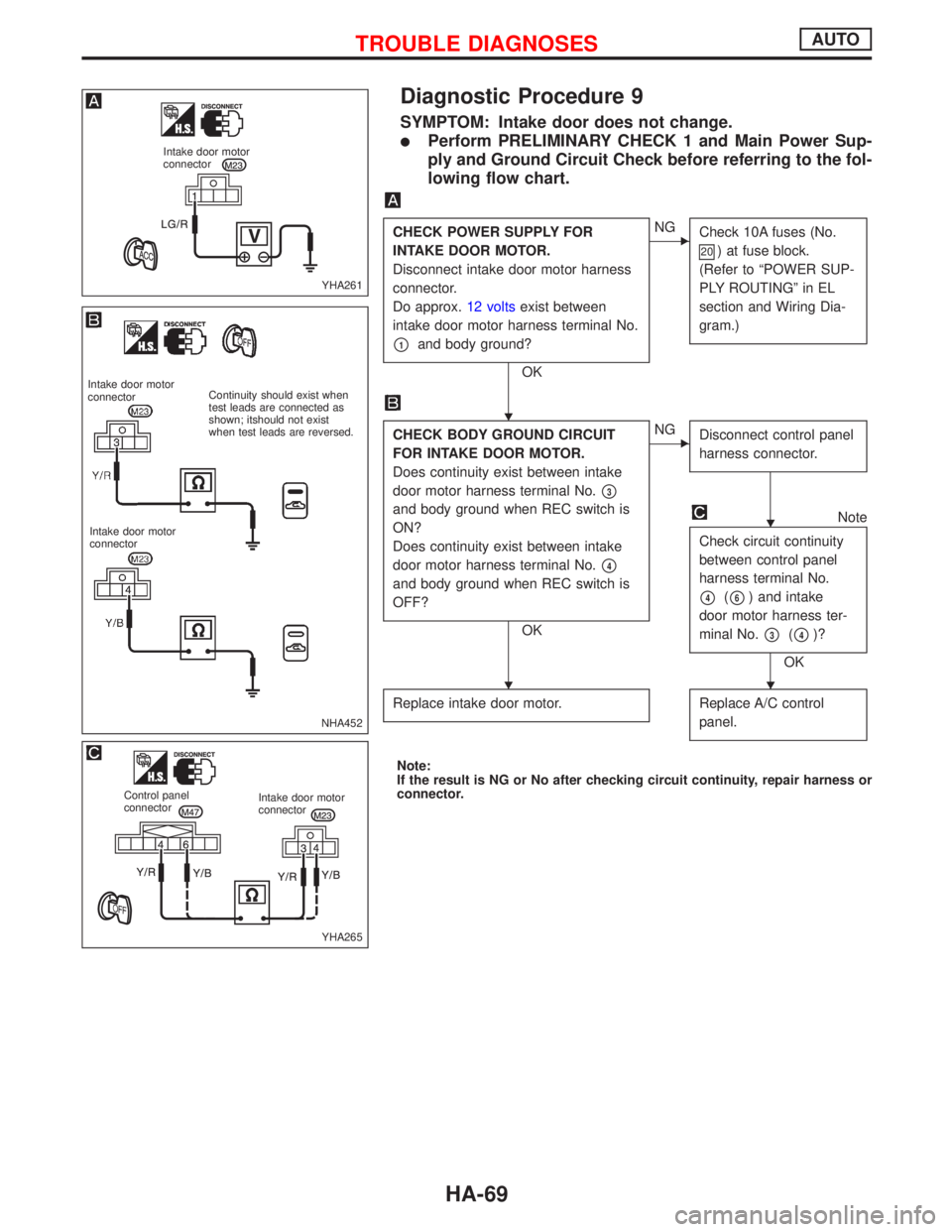
Diagnostic Procedure 9
SYMPTOM: Intake door does not change.
lPerform PRELIMINARY CHECK 1 and Main Power Sup-
ply and Ground Circuit Check before referring to the fol-
lowing flow chart.
CHECK POWER SUPPLY FOR
INTAKE DOOR MOTOR.
Disconnect intake door motor harness
connector.
Do approx.12 voltsexist between
intake door motor harness terminal No.
p1and body ground?
OK
ENG
Check 10A fuses (No.
20) at fuse block.
(Refer to ªPOWER SUP-
PLY ROUTINGº in EL
section and Wiring Dia-
gram.)
CHECK BODY GROUND CIRCUIT
FOR INTAKE DOOR MOTOR.
Does continuity exist between intake
door motor harness terminal No.
p3
and body ground when REC switch is
ON?
Does continuity exist between intake
door motor harness terminal No.
p4
and body ground when REC switch is
OFF?
OK
ENG
Disconnect control panel
harness connector.
Note
Check circuit continuity
between control panel
harness terminal No.
p4(p6) and intake
door motor harness ter-
minal No.
p3(p4)?
OK
Replace intake door motor.
Replace A/C control
panel.
Note:
If the result is NG or No after checking circuit continuity, repair harness or
connector.
YHA261
Intake door motor
connector
NHA452
Intake door motor
connectorContinuity should exist when
test leads are connected as
shown; itshould not exist
when test leads are reversed.
Intake door motor
connector
YHA265
Control panel
connectorIntake door motor
connector
H
H
HH
TROUBLE DIAGNOSESAUTO
HA-69
Page 1919 of 2267
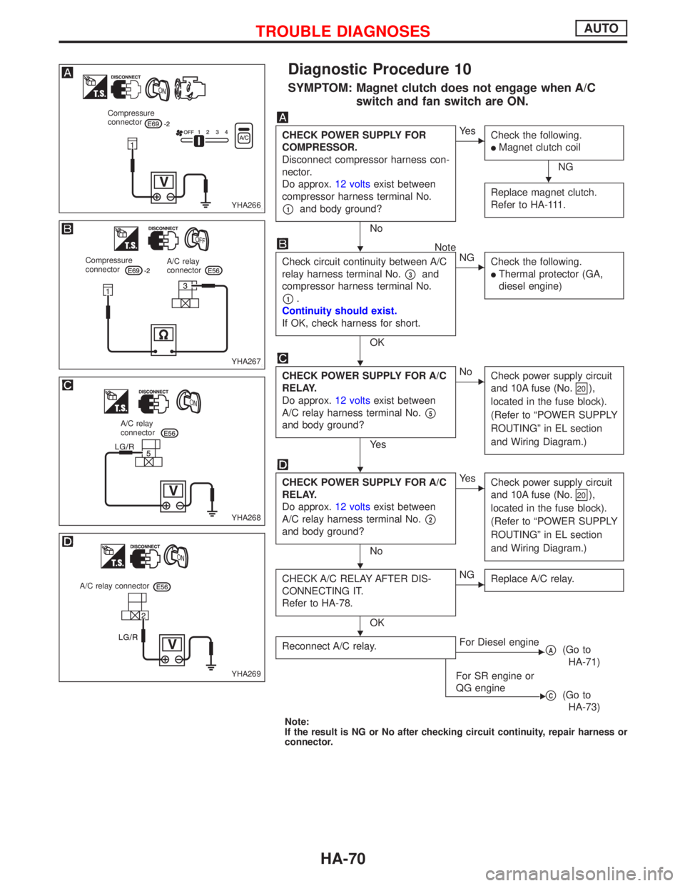
Diagnostic Procedure 10
SYMPTOM: Magnet clutch does not engage when A/C
switch and fan switch are ON.
CHECK POWER SUPPLY FOR
COMPRESSOR.
Disconnect compressor harness con-
nector.
Do approx.12 voltsexist between
compressor harness terminal No.
p1and body ground?
No
EYe s
Check the following.
lMagnet clutch coil
NG
Replace magnet clutch.
Refer to HA-111.
Note
Check circuit continuity between A/C
relay harness terminal No.
p3and
compressor harness terminal No.
p1.
Continuity should exist.
If OK, check harness for short.
OK
ENG
Check the following.
lThermal protector (GA,
diesel engine)
CHECK POWER SUPPLY FOR A/C
RELAY.
Do approx.12 voltsexist between
A/C relay harness terminal No.
p5
and body ground?
Ye s
ENo
Check power supply circuit
and 10A fuse (No.
20),
located in the fuse block).
(Refer to ªPOWER SUPPLY
ROUTINGº in EL section
and Wiring Diagram.)
CHECK POWER SUPPLY FOR A/C
RELAY.
Do approx.12 voltsexist between
A/C relay harness terminal No.
p2
and body ground?
No
EYe s
Check power supply circuit
and 10A fuse (No.
20),
located in the fuse block).
(Refer to ªPOWER SUPPLY
ROUTINGº in EL section
and Wiring Diagram.)
CHECK A/C RELAY AFTER DIS-
CONNECTING IT.
Refer to HA-78.
OK
ENG
Replace A/C relay.
Reconnect A/C relay.EFor Diesel enginepA(Go to
HA-71)
E
For SR engine or
QG engine
pC(Go to
HA-73)
Note:
If the result is NG or No after checking circuit continuity, repair harness or
connector.
YHA266
Compressure
connector
YHA267
Compressure
connectorA/C relay
connector
YHA268
A/C relay
connector
YHA269
A/C relay connector
H
H
H
H
H
H
TROUBLE DIAGNOSESAUTO
HA-70
Page 1920 of 2267
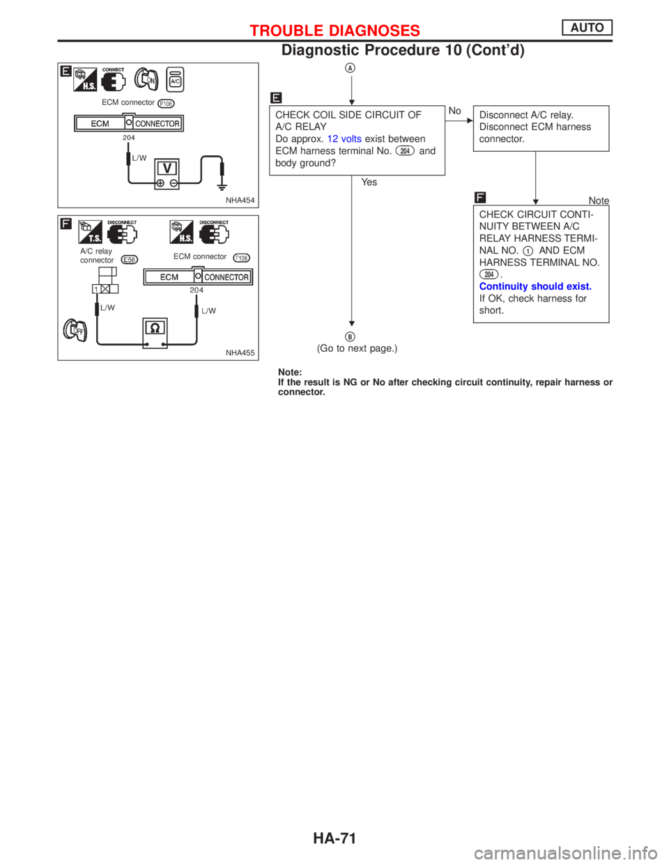
pA
CHECK COIL SIDE CIRCUIT OF
A/C RELAY
Do approx.12 voltsexist between
ECM harness terminal No.
204and
body ground?
Ye s
ENo
Disconnect A/C relay.
Disconnect ECM harness
connector.
Note
CHECK CIRCUIT CONTI-
NUITY BETWEEN A/C
RELAY HARNESS TERMI-
NAL NO.
p1AND ECM
HARNESS TERMINAL NO.
204.
Continuity should exist.
If OK, check harness for
short.
pB
(Go to next page.)
Note:
If the result is NG or No after checking circuit continuity, repair harness or
connector.
NHA454
ECM connector
NHA455
A/C relay
connectorECM connector
H
H
H
TROUBLE DIAGNOSESAUTO
Diagnostic Procedure 10 (Cont'd)
HA-71