NISSAN PRIMERA 1999 Electronic Repair Manual
Manufacturer: NISSAN, Model Year: 1999, Model line: PRIMERA, Model: NISSAN PRIMERA 1999Pages: 2267, PDF Size: 35.74 MB
Page 831 of 2267
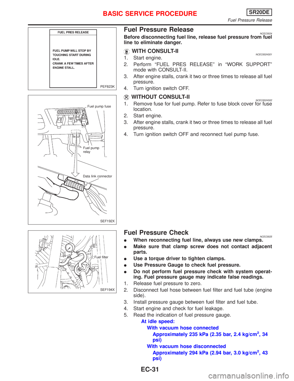
Fuel Pressure ReleaseNCEC0024Before disconnecting fuel line, release fuel pressure from fuel
line to eliminate danger.
WITH CONSULT-IINCEC0024S011. Start engine.
2. Perform ªFUEL PRES RELEASEº in ªWORK SUPPORTº
mode with CONSULT-II.
3. After engine stalls, crank it two or three times to release all fuel
pressure.
4. Turn ignition switch OFF.
WITHOUT CONSULT-IINCEC0024S021. Remove fuse for fuel pump. Refer to fuse block cover for fuse
location.
2. Start engine.
3. After engine stalls, crank it two or three times to release all fuel
pressure.
4. Turn ignition switch OFF and reconnect fuel pump fuse.
Fuel Pressure CheckNCEC0025IWhen reconnecting fuel line, always use new clamps.
IMake sure that clamp screw does not contact adjacent
parts.
IUse a torque driver to tighten clamps.
IUse Pressure Gauge to check fuel pressure.
IDo not perform fuel pressure check with system operat-
ing. Fuel pressure gauge may indicate false readings.
1. Release fuel pressure to zero.
2. Disconnect fuel hose between fuel filter and fuel tube (engine
side).
3. Install pressure gauge between fuel filter and fuel tube.
4. Start engine and check for fuel leakage.
5. Read the indication of fuel pressure gauge.
At idle speed:
With vacuum hose connected
Approximately 235 kPa (2.35 bar, 2.4 kg/cm
2,34
psi)
With vacuum hose disconnected
Approximately 294 kPa (2.94 bar, 3.0 kg/cm
2,43
psi)
PEF823K
Fuel pump fuse
Fuel pump
relay
Data link connector
SEF192X
Fuel filter
SEF194X
BASIC SERVICE PROCEDURESR20DE
Fuel Pressure Release
EC-31
Page 832 of 2267
If results are unsatisfactory, perform Fuel Pressure Regulator
Check, EC-SR-32.
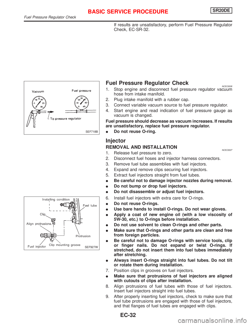
Fuel Pressure Regulator CheckNCEC00261. Stop engine and disconnect fuel pressure regulator vacuum
hose from intake manifold.
2. Plug intake manifold with a rubber cap.
3. Connect variable vacuum source to fuel pressure regulator.
4. Start engine and read indication of fuel pressure gauge as
vacuum is changed.
Fuel pressure should decrease as vacuum increases. If results
are unsatisfactory, replace fuel pressure regulator.
IDo not reuse O-ring.
Injector
REMOVAL AND INSTALLATIONNCEC00271. Release fuel pressure to zero.
2. Disconnect fuel hoses and injector harness connectors.
3. Remove fuel tube assemblies with fuel injectors.
4. Expand and remove clips securing fuel injectors.
5. Extract fuel injectors straight from fuel tubes.
IBe careful not to damage injector nozzles during removal.
IDo not bump or drop fuel injectors.
IDo not disassemble or adjust fuel injectors.
6. Install fuel injectors with extra care for O-rings.
IDo not reuse O-rings.
IUse bare hands to install O-rings. Do not wear gloves.
IApply a coat of new engine oil (with a low viscosity of
5W-30, etc.) to O-rings before installation.
IDo not use solvent to clean O-rings and other parts.
IMake sure that O-rings and other parts are clean and free
from foreign particles.
IBe careful not to damage O-rings with service tools, clip
or finger nails. Do not expand or twist O-rings. If
stretched, do not insert them into fuel tubes immediately
after stretching.
IAlways insert O-rings straight into fuel tubes. Do not tilt
or rotate them during installation.
7. Position clips in grooves on fuel injectors.
IMake sure that protrusions of fuel injectors are aligned
with cutouts of clips after installation.
8. Align protrusions of fuel tubes with those of fuel injectors.
Insert fuel injectors straight into fuel tubes.
9. After properly inserting fuel injectors, check to make sure that
fuel tube protrusions are engaged with those of fuel injectors,
and that flanges of fuel tubes are engaged with clips.
SEF718B
SEF927W
BASIC SERVICE PROCEDURESR20DE
Fuel Pressure Regulator Check
EC-32
Page 833 of 2267
IDiscard old clips; replace with new ones.
10. Install injectors with fuel tube assembly to intake manifold.
IPay extra care to prevent O-rings from being scratched by
sharp edges.
IApply a coat of new engine oil to O-rings before installa-
tion.
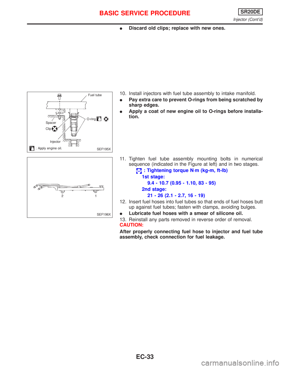
11. Tighten fuel tube assembly mounting bolts in numerical
sequence (indicated in the Figure at left) and in two stages.
: Tightening torque N×m (kg-m, ft-lb)
1st stage:
9.4 - 10.7 (0.95 - 1.10, 83 - 95)
2nd stage:
21 - 26 (2.1 - 2.7, 16 - 19)
12. Insert fuel hoses into fuel tubes so that ends of fuel hoses butt
up against fuel tubes; fasten with clamps, avoiding bulges.
ILubricate fuel hoses with a smear of silicone oil.
13. Reinstall any parts removed in reverse order of removal.
CAUTION:
After properly connecting fuel hose to injector and fuel tube
assembly, check connection for fuel leakage.
Fuel tube
O-ring
Spacer
Clip
Injector
Apply engine oil.
SEF195X
SEF196X
BASIC SERVICE PROCEDURESR20DE
Injector (Cont'd)
EC-33
Page 834 of 2267
Idle Speed/Ignition Timing/Idle Mixture Ratio
Adjustment
NCEC0028PREPARATIONNCEC0028S01IMake sure that the following parts are in good order.
a)Battery
b)Ignition system
c)Engine oil and coolant levels
d)Fuses
e)ECM harness connector
f)Vacuum hoses
g)Air intake system
(Oil filler cap, oil level gauge, etc.)
h)Fuel pressure
i)Engine compression
j)Throttle valve
k)EVAP system
IOn models equipped with air conditioner, checks should
be carried out while the air conditioner is ªOFFº.
IWhen checking idle speed on models equipped with CVT,
ignition timing and mixture ratio, checks should be carried
out while shift lever is in ªPº or ªNº position.
IWhen measuring ªCOº percentage, insert probe more
than 40 cm (15.7 in) into tail pipe.
ITurn off headlamps, heater blower, rear window defogger.
IOn vehicles equipped with daytime running light systems,
set lighting switch to the 1st position to light only small
lamps.
IKeep front wheels pointed straight ahead.
IIf engine stops immediately after starting or idle condition
is unstable, perform the following to initialize IACV-AAC
valve:
a)Stop engine and wait 9 seconds.
b)Turn ignition ªONº and wait 1 second.
c)Turn ignition ªOFFº and wait 9 seconds.
IMake the check after the cooling fan has stopped.
BASIC SERVICE PROCEDURESR20DE
Idle Speed/Ignition Timing/Idle Mixture Ratio Adjustment
EC-34
Page 835 of 2267
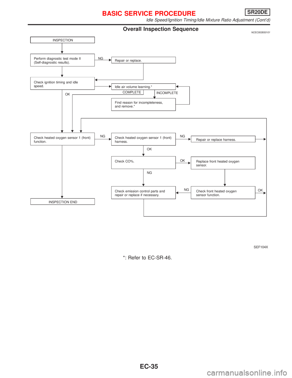
Overall Inspection SequenceNCEC0028S0101
*: Refer to EC-SR-46.
SEF104X INSPECTION
Perform diagnostic test mode II
(Self-diagnostic results).Repair or replace. NG
Check ignition timing and idle
speed.
Idle air volume learning.*
COMPLETE
INCOMPLETE
Find reason for incompleteness,
and remove.* OK
Check heated oxygen sensor 1 (front)
function.NG
Check heated oxygen sensor 1 (front)
harness.NG
OK
Check CO%.
NGOK
INSPECTION ENDCheck emission control parts and
repair or replace if necessary.NGRepair or replace harness.
Replace front heated oxygen
sensor.
Check front heated oxygen
sensor function.OK H
BASIC SERVICE PROCEDURESR20DE
Idle Speed/Ignition Timing/Idle Mixture Ratio Adjustment (Cont'd)
EC-35
Page 836 of 2267
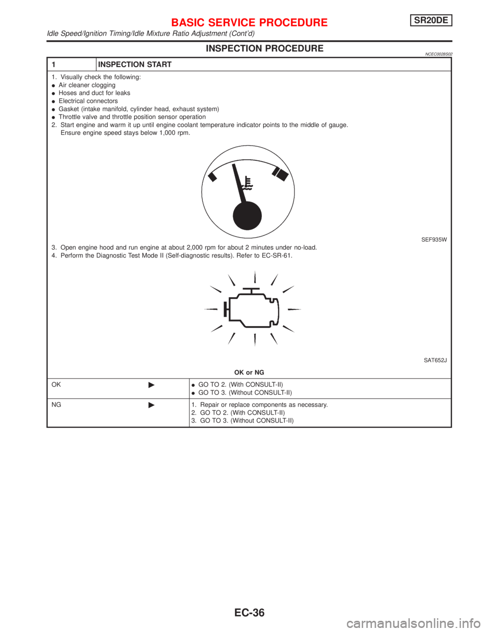
INSPECTION PROCEDURENCEC0028S02
1 INSPECTION START
1. Visually check the following:
IAir cleaner clogging
IHoses and duct for leaks
IElectrical connectors
IGasket (intake manifold, cylinder head, exhaust system)
IThrottle valve and throttle position sensor operation
2. Start engine and warm it up until engine coolant temperature indicator points to the middle of gauge.
Ensure engine speed stays below 1,000 rpm.
SEF935W3. Open engine hood and run engine at about 2,000 rpm for about 2 minutes under no-load.
4. Perform the Diagnostic Test Mode II (Self-diagnostic results). Refer to EC-SR-61.
SAT652J
OK or NG
OK©IGO TO 2. (With CONSULT-II)
IGO TO 3. (Without CONSULT-II)
NG©1. Repair or replace components as necessary.
2. GO TO 2. (With CONSULT-II)
3. GO TO 3. (Without CONSULT-II)
BASIC SERVICE PROCEDURESR20DE
Idle Speed/Ignition Timing/Idle Mixture Ratio Adjustment (Cont'd)
EC-36
Page 837 of 2267
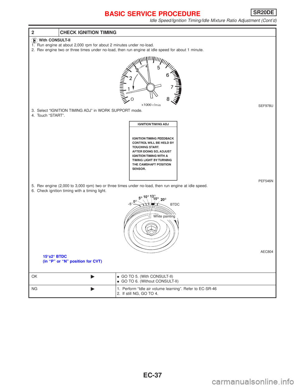
2 CHECK IGNITION TIMING
With CONSULT-II
1. Run engine at about 2,000 rpm for about 2 minutes under no-load.
2. Rev engine two or three times under no-load, then run engine at idle speed for about 1 minute.
SEF978U3. Select ªIGNITION TIMING ADJº in WORK SUPPORT mode.
4. Touch ªSTARTº.
PEF546N5. Rev engine (2,000 to 3,000 rpm) two or three times under no-load, then run engine at idle speed.
6. Check ignition timing with a timing light.
AEC80415É 2É BTDC
(in ªPº or ªNº position for CVT)
OK©IGO TO 5. (With CONSULT-II)
IGO TO 6. (Without CONSULT-II)
NG©1. Perform ªIdle air volume learningº. Refer to EC-SR-46
2. If still NG, GO TO 4.
BTDC
White painting
BASIC SERVICE PROCEDURESR20DE
Idle Speed/Ignition Timing/Idle Mixture Ratio Adjustment (Cont'd)
EC-37
Page 838 of 2267
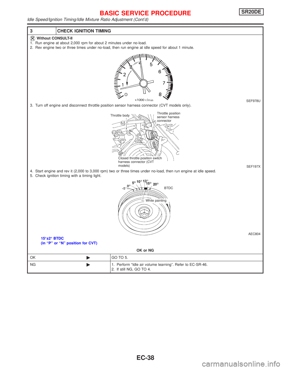
3 CHECK IGNITION TIMING
Without CONSULT-II
1. Run engine at about 2,000 rpm for about 2 minutes under no-load.
2. Rev engine two or three times under no-load, then run engine at idle speed for about 1 minute.
SEF978U3. Turn off engine and disconnect throttle position sensor harness connector (CVT models only).
SEF197X4. Start engine and rev it (2,000 to 3,000 rpm) two or three times under no-load, then run engine at idle speed.
5. Check ignition timing with a timing light.
AEC80415É 2É BTDC
(in ªPº or ªNº position for CVT)
OK or NG
OK©GO TO 5.
NG©1. Perform ªIdle air volume learningº. Refer to EC-SR-46.
2. If still NG, GO TO 4.
Throttle position
sensor harness
connector Throttle body
Closed throttle position switch
harness connector (CVT
models)
BTDC
White painting
BASIC SERVICE PROCEDURESR20DE
Idle Speed/Ignition Timing/Idle Mixture Ratio Adjustment (Cont'd)
EC-38
Page 839 of 2267
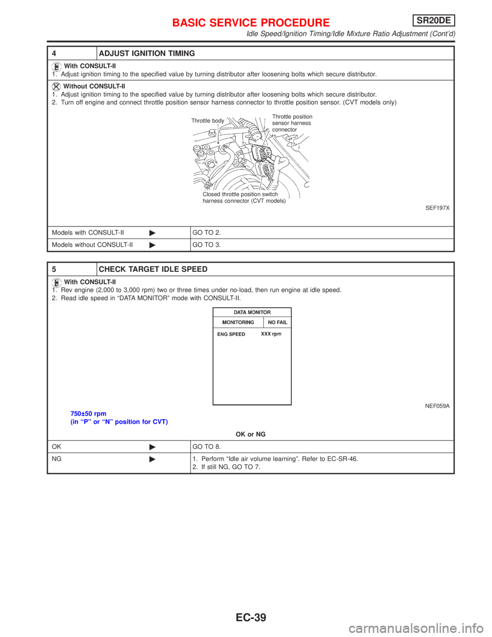
4 ADJUST IGNITION TIMING
With CONSULT-II
1. Adjust ignition timing to the specified value by turning distributor after loosening bolts which secure distributor.
Without CONSULT-II
1. Adjust ignition timing to the specified value by turning distributor after loosening bolts which secure distributor.
2. Turn off engine and connect throttle position sensor harness connector to throttle position sensor. (CVT models only)
SEF197X
Models with CONSULT-II©GO TO 2.
Models without CONSULT-II©GO TO 3.
5 CHECK TARGET IDLE SPEED
With CONSULT-II
1. Rev engine (2,000 to 3,000 rpm) two or three times under no-load, then run engine at idle speed.
2. Read idle speed in ªDATA MONITORº mode with CONSULT-II.
NEF059A750 50 rpm
(in ªPº or ªNº position for CVT)
OK or NG
OK©GO TO 8.
NG©1. Perform ªIdle air volume learningº. Refer to EC-SR-46.
2. If still NG, GO TO 7.
Throttle position
sensor harness
connector Throttle body
Closed throttle position switch
harness connector (CVT models)
BASIC SERVICE PROCEDURESR20DE
Idle Speed/Ignition Timing/Idle Mixture Ratio Adjustment (Cont'd)
EC-39
Page 840 of 2267
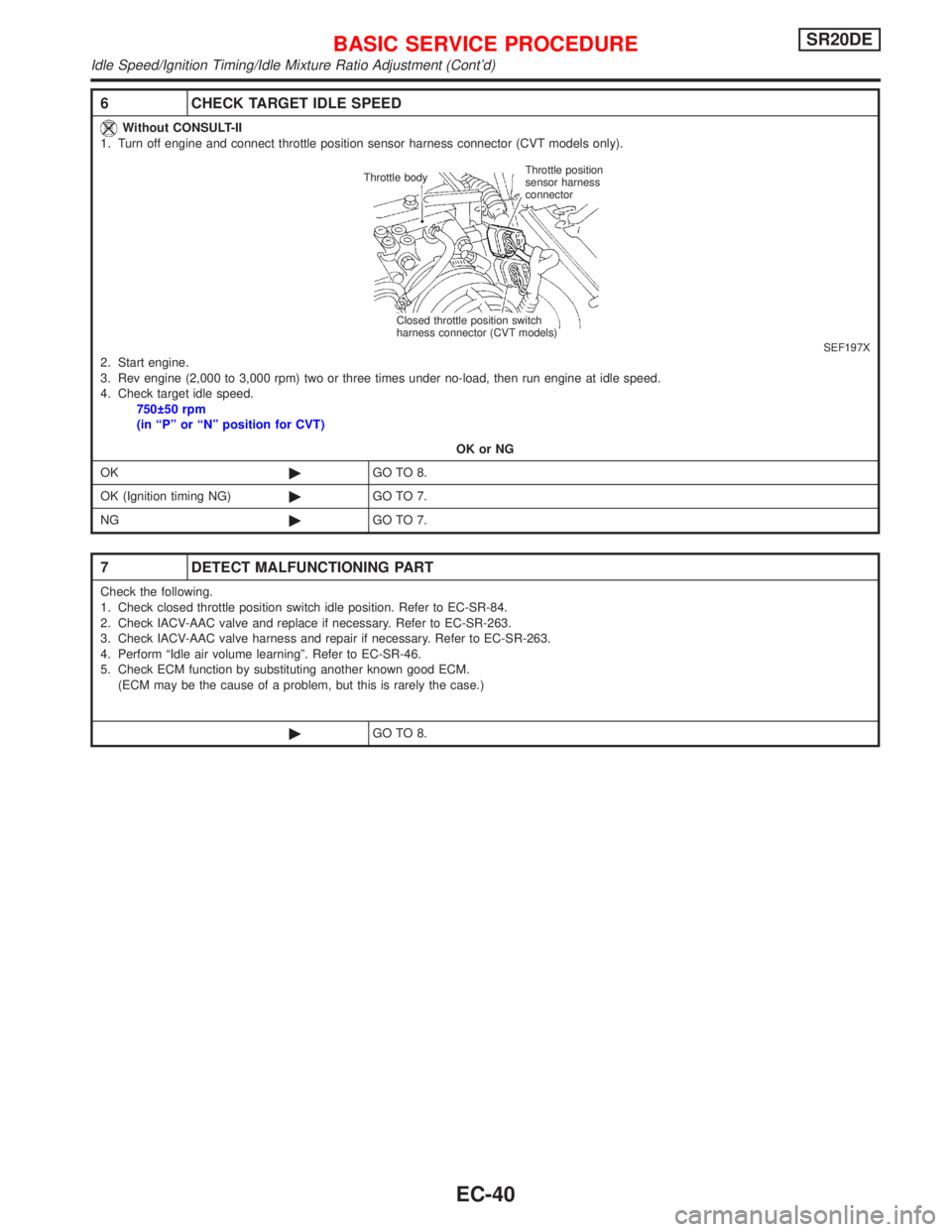
6 CHECK TARGET IDLE SPEED
Without CONSULT-II
1. Turn off engine and connect throttle position sensor harness connector (CVT models only).
SEF197X2. Start engine.
3. Rev engine (2,000 to 3,000 rpm) two or three times under no-load, then run engine at idle speed.
4. Check target idle speed.
750 50 rpm
(in ªPº or ªNº position for CVT)
OK or NG
OK©GO TO 8.
OK (Ignition timing NG)©GO TO 7.
NG©GO TO 7.
7 DETECT MALFUNCTIONING PART
Check the following.
1. Check closed throttle position switch idle position. Refer to EC-SR-84.
2. Check IACV-AAC valve and replace if necessary. Refer to EC-SR-263.
3. Check IACV-AAC valve harness and repair if necessary. Refer to EC-SR-263.
4. Perform ªIdle air volume learningº. Refer to EC-SR-46.
5. Check ECM function by substituting another known good ECM.
(ECM may be the cause of a problem, but this is rarely the case.)
©GO TO 8.
Throttle position
sensor harness
connector Throttle body
Closed throttle position switch
harness connector (CVT models)
BASIC SERVICE PROCEDURESR20DE
Idle Speed/Ignition Timing/Idle Mixture Ratio Adjustment (Cont'd)
EC-40