NISSAN PRIMERA 1999 Electronic Repair Manual
PRIMERA 1999
NISSAN
NISSAN
https://www.carmanualsonline.info/img/5/57377/w960_57377-0.png
NISSAN PRIMERA 1999 Electronic Repair Manual
Trending: run flat, oil, language, recommended oil, wheel torque, instrument cluster, heater
Page 791 of 2267
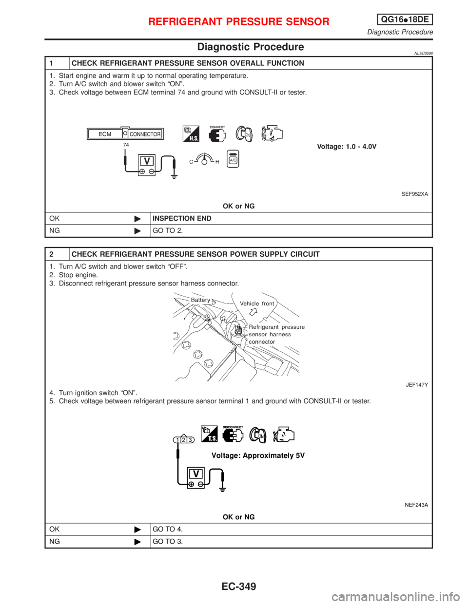
Diagnostic ProcedureNLEC0590
1 CHECK REFRIGERANT PRESSURE SENSOR OVERALL FUNCTION
1. Start engine and warm it up to normal operating temperature.
2. Turn A/C switch and blower switch ªONº.
3. Check voltage between ECM terminal 74 and ground with CONSULT-II or tester.
SEF952XA
OK or NG
OK©INSPECTION END
NG©GO TO 2.
2 CHECK REFRIGERANT PRESSURE SENSOR POWER SUPPLY CIRCUIT
1. Turn A/C switch and blower switch ªOFFº.
2. Stop engine.
3. Disconnect refrigerant pressure sensor harness connector.
JEF147Y
4. Turn ignition switch ªONº.
5. Check voltage between refrigerant pressure sensor terminal 1 and ground with CONSULT-II or tester.
NEF243A
OK or NG
OK©GO TO 4.
NG©GO TO 3.
REFRIGERANT PRESSURE SENSORQG16I18DE
Diagnostic Procedure
EC-349
Page 792 of 2267
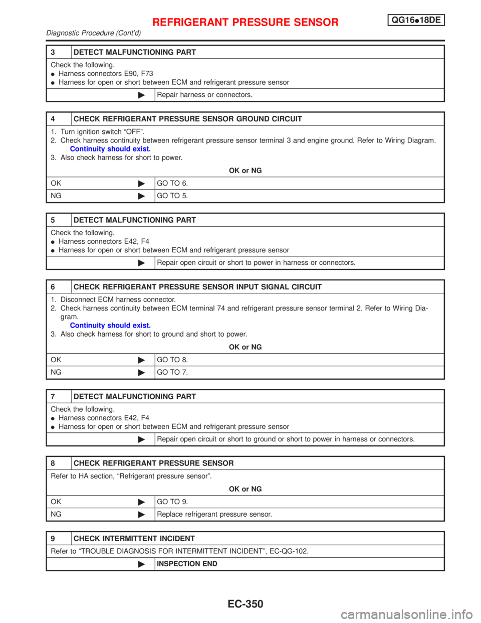
3 DETECT MALFUNCTIONING PART
Check the following.
IHarness connectors E90, F73
IHarness for open or short between ECM and refrigerant pressure sensor
©Repair harness or connectors.
4 CHECK REFRIGERANT PRESSURE SENSOR GROUND CIRCUIT
1. Turn ignition switch ªOFFº.
2. Check harness continuity between refrigerant pressure sensor terminal 3 and engine ground. Refer to Wiring Diagram.
Continuity should exist.
3. Also check harness for short to power.
OK or NG
OK©GO TO 6.
NG©GO TO 5.
5 DETECT MALFUNCTIONING PART
Check the following.
IHarness connectors E42, F4
IHarness for open or short between ECM and refrigerant pressure sensor
©Repair open circuit or short to power in harness or connectors.
6 CHECK REFRIGERANT PRESSURE SENSOR INPUT SIGNAL CIRCUIT
1. Disconnect ECM harness connector.
2. Check harness continuity between ECM terminal 74 and refrigerant pressure sensor terminal 2. Refer to Wiring Dia-
gram.
Continuity should exist.
3. Also check harness for short to ground and short to power.
OK or NG
OK©GO TO 8.
NG©GO TO 7.
7 DETECT MALFUNCTIONING PART
Check the following.
IHarness connectors E42, F4
IHarness for open or short between ECM and refrigerant pressure sensor
©Repair open circuit or short to ground or short to power in harness or connectors.
8 CHECK REFRIGERANT PRESSURE SENSOR
Refer to HA section, ªRefrigerant pressure sensorº.
OK or NG
OK©GO TO 9.
NG©Replace refrigerant pressure sensor.
9 CHECK INTERMITTENT INCIDENT
Refer to ªTROUBLE DIAGNOSIS FOR INTERMITTENT INCIDENTº, EC-QG-102.
©INSPECTION END
REFRIGERANT PRESSURE SENSORQG16I18DE
Diagnostic Procedure (Cont'd)
EC-350
Page 793 of 2267
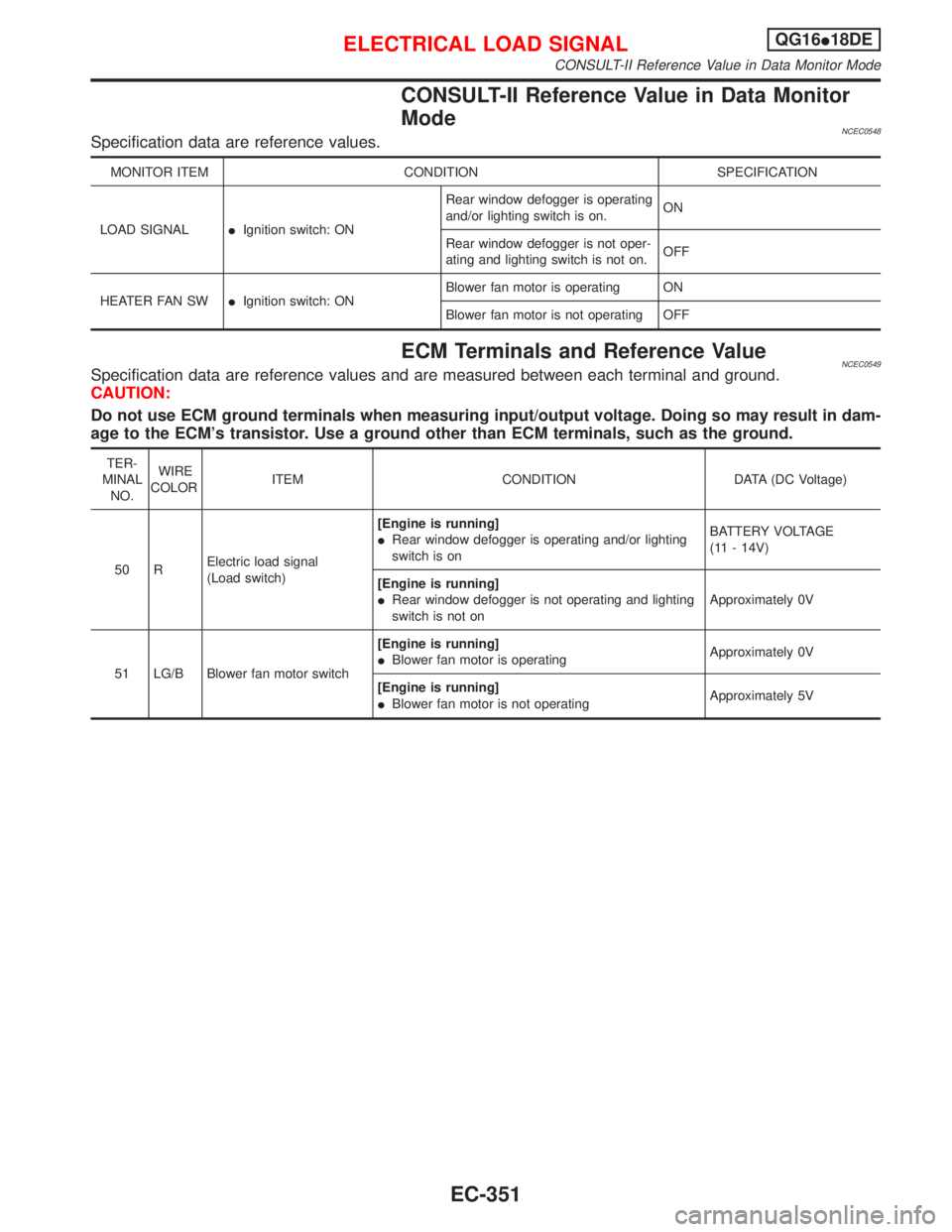
CONSULT-II Reference Value in Data Monitor
Mode
NCEC0548Specification data are reference values.
MONITOR ITEM CONDITION SPECIFICATION
LOAD SIGNALIIgnition switch: ONRear window defogger is operating
and/or lighting switch is on.ON
Rear window defogger is not oper-
ating and lighting switch is not on.OFF
HEATER FAN SWIIgnition switch: ONBlower fan motor is operating ON
Blower fan motor is not operating OFF
ECM Terminals and Reference ValueNCEC0549Specification data are reference values and are measured between each terminal and ground.
CAUTION:
Do not use ECM ground terminals when measuring input/output voltage. Doing so may result in dam-
age to the ECM's transistor. Use a ground other than ECM terminals, such as the ground.
TER-
MINAL
NO.WIRE
COLORITEM CONDITION DATA (DC Voltage)
50 RElectric load signal
(Load switch)[Engine is running]
IRear window defogger is operating and/or lighting
switch is onBATTERY VOLTAGE
(11 - 14V)
[Engine is running]
IRear window defogger is not operating and lighting
switch is not onApproximately 0V
51 LG/B Blower fan motor switch[Engine is running]
IBlower fan motor is operatingApproximately 0V
[Engine is running]
IBlower fan motor is not operatingApproximately 5V
ELECTRICAL LOAD SIGNALQG16I18DE
CONSULT-II Reference Value in Data Monitor Mode
EC-351
Page 794 of 2267
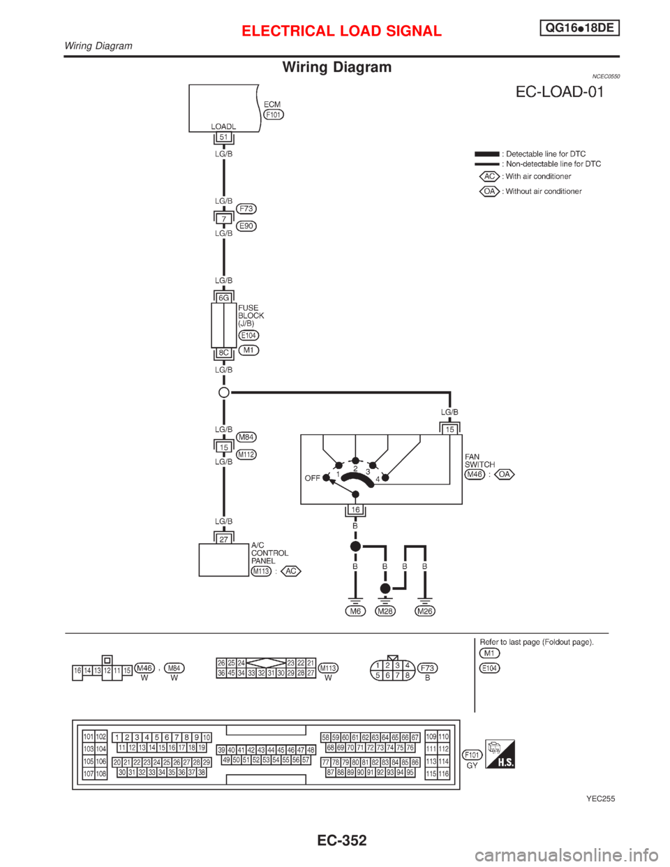
Wiring DiagramNCEC0550
YEC255
ELECTRICAL LOAD SIGNALQG16I18DE
Wiring Diagram
EC-352
Page 795 of 2267
YEC077A
ELECTRICAL LOAD SIGNALQG16I18DE
Wiring Diagram (Cont'd)
EC-353
Page 796 of 2267
Wiring DiagramNCEC0466
YEC078A
MI & DATA LINK CONNECTORSQG16I18DE
Wiring Diagram
EC-354
Page 797 of 2267
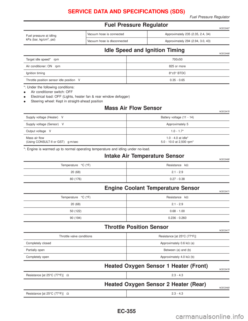
Fuel Pressure RegulatorNCEC0467
Fuel pressure at idling
kPa (bar, kg/cm2, psi)Vacuum hose is connected Approximately 235 (2.35, 2.4, 34)
Vacuum hose is disconnected Approximately 294 (2.94, 3.0, 43)
Idle Speed and Ignition TimingNCEC0468
Target idle speed* rpm700 50
Air conditioner: ON rpm825 or more
Ignition timing8É 5É BTDC
Throttle position sensor idle position V 0.35 - 0.65
*: Under the following conditions:
IAir conditioner switch: OFF
IElectrical load: OFF (Lights, heater fan & rear window defogger)
ISteering wheel: Kept in straight-ahead position
Mass Air Flow SensorNCEC0470
Supply voltage (Heater) VBattery voltage (11 - 14)
Supply voltage (Sensor) VApproximately 5
Output voltage V1.0 - 1.7*
Mass air flow
(Using CONSULT-II or GST) g×m/sec1.0 - 4.0 at idle*
5.0 - 10.0 at 2,500 rpm*
*: Engine is warmed up to normal operating temperature and idling under no-load.
Intake Air Temperature SensorNCEC0480
Temperature ÉC (ÉF) Resistance kW
20 (68) 2.1 - 2.9
80 (176) 0.27 - 0.38
Engine Coolant Temperature SensorNCEC0471
Temperature ÉC (ÉF) Resistance kW
20 (68) 2.1 - 2.9
50 (122) 0.68 - 1.00
90 (194) 0.236 - 0.260
Throttle Position SensorNCEC0477
Throttle valve conditions Resistance [at 25ÉC (77ÉF)]
Completely closedApproximately 0.6 kW(a)
Partially openBetween (a) and (b)
Completely openApproximately 4.0 kW(b)
Heated Oxygen Sensor 1 Heater (Front)NCEC0478
Resistance [at 25ÉC (77ÉF)]W2.3 - 4.3
Heated Oxygen Sensor 2 Heater (Rear)NCEC0483
Resistance [at 25ÉC (77ÉF)]W2.3 - 4.3
SERVICE DATA AND SPECIFICATIONS (SDS)
Fuel Pressure Regulator
EC-355
Page 798 of 2267
Crankshaft Position Sensor (POS)NCEC0558
Terminal No. (Polarity) ResistanceW[at 25ÉC (77ÉF)]
3 (+) - 1 (þ)
Except 0 or¥ 2 (+) - 1 (þ)
3 (+) - 2 (þ)
Camshaft Position Sensor (PHASE)NCEC0559
Terminal No. (Polarity) ResistanceW[at 25ÉC (77ÉF)]
3 (+) - 1 (þ)
Except 0 or¥ 2 (+) - 1 (þ)
3 (+) - 2 (þ)
EGR Volume Control Valve (If so equipped)NCEC0560
Terminal No. ResistanceW[at 20ÉC (68ÉF)]
1-2
20-24 2-3
4-5
5-6
EGR Temperature Sensor (If so equipped)NCEC0472
EGR temperature
ÉC (ÉF)Voltage
VResistance
MW
0 (32) 4.56 0.62 - 1.05
50 (122) 2.25 0.065 - 0.094
100 (212) 0.59 0.011 - 0.015
EVAP Canister Purge Volume Control ValveNCEC0481
Resistance [at 20ÉC (68ÉF)]W31-35
IACV-AAC ValveNCEC0474
Terminal No. ResistanceW[at 20ÉC (68ÉF)]
1-2
20-24 2-3
4-5
5-6
InjectorNCEC0475
Resistance [at 25ÉC (77ÉF)]W13.5 - 17.5
SERVICE DATA AND SPECIFICATIONS (SDS)
Crankshaft Position Sensor (POS)
EC-356
Page 799 of 2267
Ignition Coil with Power TransistorNCEC0561
Terminal No. (Polarity) ResistanceW[at 25ÉC (77ÉF)]
3 (+) - 2 (þ) Except 0 or¥
1 (+) - 3 (þ)
Except 0
1 (+) - 2 (þ)
Fuel PumpNCEC0473
Resistance [at 25ÉC (77ÉF)]W0.2 - 5.0
SERVICE DATA AND SPECIFICATIONS (SDS)
Ignition Coil with Power Transistor
EC-357
Page 800 of 2267
NOTE
SERVICE DATA AND SPECIFICATIONS (SDS)
EC-358
Trending: brake sensor, remote control, brake rotor, service reset, maintenance schedule, oil viscosity, width




![NISSAN PRIMERA 1999 Electronic Repair Manual Crankshaft Position Sensor (POS)NCEC0558
Terminal No. (Polarity) ResistanceW[at 25ÉC (77ÉF)]
3 (+) - 1 (þ)
Except 0 or¥ 2 (+) - 1 (þ)
3 (+) - 2 (þ)
Camshaft Position Sensor (PHASE)NCEC0559
Termi NISSAN PRIMERA 1999 Electronic Repair Manual Crankshaft Position Sensor (POS)NCEC0558
Terminal No. (Polarity) ResistanceW[at 25ÉC (77ÉF)]
3 (+) - 1 (þ)
Except 0 or¥ 2 (+) - 1 (þ)
3 (+) - 2 (þ)
Camshaft Position Sensor (PHASE)NCEC0559
Termi](/img/5/57377/w960_57377-797.png)
![NISSAN PRIMERA 1999 Electronic Repair Manual Ignition Coil with Power TransistorNCEC0561
Terminal No. (Polarity) ResistanceW[at 25ÉC (77ÉF)]
3 (+) - 2 (þ) Except 0 or¥
1 (+) - 3 (þ)
Except 0
1 (+) - 2 (þ)
Fuel PumpNCEC0473
Resistance [at 2 NISSAN PRIMERA 1999 Electronic Repair Manual Ignition Coil with Power TransistorNCEC0561
Terminal No. (Polarity) ResistanceW[at 25ÉC (77ÉF)]
3 (+) - 2 (þ) Except 0 or¥
1 (+) - 3 (þ)
Except 0
1 (+) - 2 (þ)
Fuel PumpNCEC0473
Resistance [at 2](/img/5/57377/w960_57377-798.png)
